HAL Id: hal-02154021
https://hal-univ-pau.archives-ouvertes.fr/hal-02154021
Submitted on 5 Oct 2020
HAL is a multi-disciplinary open access
archive for the deposit and dissemination of sci-entific research documents, whether they are pub-lished or not. The documents may come from teaching and research institutions in France or abroad, or from public or private research centers.
L’archive ouverte pluridisciplinaire HAL, est destinée au dépôt et à la diffusion de documents scientifiques de niveau recherche, publiés ou non, émanant des établissements d’enseignement et de recherche français ou étrangers, des laboratoires publics ou privés.
Study of the Reinforced Concrete Structures
Containment
G. Nahas, B. Cirée, M. Quesada, T. Gelain, A. Loukili, G. Medgigbodo, A.
Khelidj, M. Choinska, J.P. Regoin, F. Benboudjema, et al.
To cite this version:
G. Nahas, B. Cirée, M. Quesada, T. Gelain, A. Loukili, et al.. Study of the Reinforced Concrete Structures Containment. 2nd International Conference on Technological Innovations in Nuclear Civil Engineering, Sep 2014, Paris, France. pp.13. �hal-02154021�
Technical Innovation in Nuclear Civil Engineering – TINCE 2014
Paris (France), September 1st– 4th, 2014
Study of the Reinforced Concrete Structures Containment
G. Nahas1,3, B. Cirée1, M. Quesada1, T. Gelain1
A. Loukili2, S. Gildas Medjigbodo2, A. Khelidj2, M. Choinska2, J-P. Regoin2
F. Benboudjema3, A. Darquennes3, A. Hilaire3,1, R. Bennacer3, G. Rastiello3,1
C. La Borderie4, C. Lawrence4
J. Dubreuil5, M-C. Barbaroux5
C. Gilliot6
1IRSN : Institut de Radioprotection et de Sûreté Nucléaire, Fontenay aux Roses, France ([email protected]) 2GeM : Institut de Recherche en Génie Civil et Mécanique, Nantes, France.
3
LMT-Cachan, ENS Cachan, CNRS, Universud Paris PRES, France
4SIAME-Université de Pau et des Pays de l’Adour, France 5Nuvia Travaux Spéciaux, Aix-en-Provence, France 6APAVE-Agence de Niort, France
Introduction
Double-wall containment buildings for pressurized water nuclear power plants consist of a reinforced concrete outer wall and a biaxially pre-stressed concrete inner wall. The leak-tightness of the inner wall is a primary safety requirement. This structure that ensures the containment of the radionuclides may crack during its construction, or in service loading. This cracking tends to reduce the leak-tightness of the wall in the event of a serious accident (accidental pressure and temperature loads). Quantifying this risk of leakage has been the subject of several models for which the parameters were obtained from tests on the material scale. Given that it is difficult, or even impossible, to perform an experiment on the real structure, it is necessary to resort to numerical simulation. The difficulty involved is related to the numerical models used, which must be capable of simulating both the mechanical behavior of the structure (macroscopic scale) and the geometry of the cracks (mesoscopic scale). The development of a reliable tool to assess leakage through a reinforced and prestressed concrete wall under severe pressure conditions with possible thermal loads, which will allow the models and methods implemented in the calculation software to be verified, thus becomes a key objective.
This is the purpose of the ECOBA project (Study of Reinforced Concrete Structure Containment) and the validation of this tool is done by means of an experimental study using a representative structure member Mock-up. This project was conducted by A. Loukili (GEM) over the period 2010-2014, as part of collaboration between the IRSN and three laboratories with complementary skills: GeM, SIAME and LMT. These teams obtained support from the French National Research
Agency (ANR) as part of a so called "White Program". The project was also labeled by the competitiveness workgroup Advancity, Sustainable City and Mobility. The construction, on the site of the Ecole Centrale de Nantes, of two Mock-ups representing a current portion of a 2.40 m high and 3.90 m wide inner containment wall was entrusted to NUVIA Travaux Spéciaux and the technical control of the test was entrusted to APAVE-Agence de Niort. The scientific issues studied are: the early-age behavior of concrete with the appearance of micro cracking, changes in its permeability and flows through localized cracks under severe accident conditions or under the effect of pressure (5 bar) and temperature (150°C), with simulations at the mesoscopic and macroscopic scales. This paper presents the experimental part of the project, the technical solutions implemented, in particular the design of Mock-ups, the devices for creating and monitoring crack apertures and leak rate measurement. An overview of the research conducted in the framework of this project is also briefly discussed.
Design of the Mock-up
The design of the Mock-up is an essential step of the project, since it must allow a proper validation of the models and methods implemented in the calculation software applications used. The important parameters that have guided this design are: the geometric representativeness of the section in relation to the current portion of a P4 type reactor inner containment wall, the representativeness of circumferential stress in accidental loads, the homogeneity of the stresses in the section in order to avoid parasitic forces localization near loads application areas and the simplicity of the boundary conditions to facilitate numerical simulations.
Five configurations with different shapes, geometries and structures were studied. These configurations were analyzed using finite element calculations with the CAST3M software, taking into account the non-linear behavior of the concrete and the reinforcement. The idea is to ensure continually relevance of each configuration with respect to the objectives of the experiment. The final configuration chosen is that of a bone-shaped Mock-up, comprising two heavily reinforced and prestressed soles and a "zone of interest" surrounded by two transition zones with brackets at 30° degrees, for connecting the "zone of interest" to the soles. This choice allows a homogeneous distribution of the deformations in the "zone of interest" for the crack aperture and leakage flow rate measurements after the area is subjected to traction. The 1.50m wide, 1.20m high and 0.90m thick "zone of interest" represents a current portion of the
containment building. Thus, with the soles and transition zones, the Mock-up reaches a length of 3.90m and a height of 2.40m, with a mass of about 20 tons. The "zone of interest" is made of a type of concrete known as B11, the formulation of which is representative of the concrete used for containment buildings, and the soles are made of self-compacting concrete (Figure 1).
Figure 1 - Schematic Mock-up
Horizontal tendon sheaths were modeled to study their influence on the mechanical behavior and on leakage paths. Due to the small size of the Mock-up, the prestressing tendons were replaced by an equivalent reinforcement by the means of slightly tensioned HA32 threaded rods. This reinforcement ensures the forces balance in the Mock-up section (concrete and reinforcement) after the cracking of the concrete and also allows better control of the crack openings created in the concrete. The sole is transversely prestressed by means of four prestressing tendons. A steel plate is set up to ensure the leak-tightness of the two lateral faces of the "zone of interest".
In order to avoid the problem of loosening of the transition area and loss of mechanical force continuity during loading, pin-shaped HA8 hook connectors, with an extended length of 33 cm are distributed over the entire rear face of each steel plate (Figure 2).
Two Mock-ups ("Model 1" and "Model 2") were made successively on the experimental platform to build upon the experience feedback of the first Mock-up, especially regarding special precautions to ensure the leak-tightness between the partition plates and the "zone of interest". The geometry and construction layout of both Mock-ups are identical, but the "zone of interest" of the second Mock-up includes construction joints similar to those of containment buildings, to assess their impact on the leak-tightness of the wall.
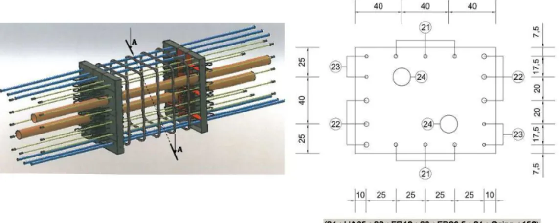
As regards the instruments embedded in the concrete, two types of sensors are positioned in the thickness of the wall in the "zone of interest", in order to monitor internal displacements (or strains) and temperature changes:
three dual-coil vibrating-wire sensors (CV) with 3D positioning for monitoring strains (and temperature using a thermistor) along the three axes,
four thermocouples (TC) positioned in the thickness of the wall (one of them at the same location as a vibrating-wire sensor for validation) to measure the temperature profile.
The location of the sensors is shown in Figure 3.
In addition to these sensors, Model 2 is equipped with stress gauges installed on the reinforcement and reservations are left for installing hygrothermal sensors.
Location of the hygrothermal sensors Location of the dual-coil vibrating-wire sensors
Figure 3 - Instruments embedded in the concrete of the Mock-up
Early-age concrete behavior
This study aims to predict the state of the initial stresses in the Mock-up. Indeed, given the massiveness of the Mock-up, the exothermic hydration reaction leads to high temperatures (about 55°C, that is a temperature increase of 40°C), inducing thermal strain gradients. Moreover, given
that drying is a diffusive phenomenon, a relative humidity gradient, and therefore a drying shrinkage gradient, appears. This creates stresses on the macroscopic scale, according to several mechanisms.
The thermal and autogenous aspects lead to two cracking mechanisms:
A self-stress mechanism: during heating, the temperature increases significantly deep inside, while remaining close to the outside temperature on the surface. The ensuing temperature gradient results in a thermal strain gradient (expansion) that generates tensile stresses on the surface and compression deep inside. These self-balanced stresses are weak, because the Young modulus is low at this stage, but the tensile strength is also weak. Upon cooling, the Young modulus of the concrete increases, the strain gradient (shrinkage contraction) is reversed relative to that of the previous phase, corresponding to heating. Tensile stresses develop deep inside, while compression stresses appear on the surface. Potential cracking occurs, first on the surface and then deeper inside: it does not go all the way through.
Concrete construction joint restraint: stresses induced by the shrinkage of the lower raised edge must be added to the earlier stress state (this concern only the second Mock-up). During the temperature increase phase, compressive stresses (weak, because the Young modulus is low at this stage) appear in the current raised edge (they are tensile stresses in the lower raised edge that may lead to cracking all the way through). Upon cooling, the stresses are reversed: the tensile stresses generated in the current raised edge can induce cracking, this time all the way through, accentuated by the autogenous shrinkage strain. Drying can be a priori neglected in this study. Indeed, on one hand water exchanges are 1000 to 10,000 times slower than the thermal phenomena and therefore concern only a thin layer of concrete, on the surface of massive structures; on the other hand, when the formwork remains in place, the drying becomes very slow. The effects of drying are similar to the thermal effects. Nevertheless, given the massiveness of the structure, only the water gradient (higher internal relative humidity rate than the external humidity rate) can induce a non-negligible stress state, while remaining comparable to that observed in a conventional concrete test piece (type 16X32, for example). Thus, cracking limited to the area close to the surface may occur.
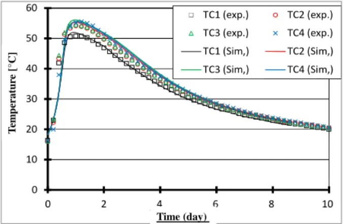
0 10 20 30 40 50 60 0 2 4 6 8 10 Te m pé ra tu re s[ °C ] Temps (jours) TC1 (exp.) TC2 (exp.) TC3 (exp.) TC4 (exp.) TC1 (Sim,) TC2 (Sim,) TC3 (Sim,) TC4 (Sim,) Time (day) T em p er a tu re [° C ]
Figure 4 - Changes in the temperature at various measuring points in the structure over time. (Presence of soles) -100 -50 0 50 100 150 200 250 300 0 2 4 6 8 10 D éf or m at io n co rr ig ée [µ m /m ] Temps (jours) CV1 CV2 CV3 CV_X CV_Y CV_Z Time (day) S tr a in [µ m /m ]
Figure 5 - Changes in the strains: comparison between the results of numerical simulations and experimentally measured values
In order to predict the initial stress state in the structure, it is necessary to model several phenomena, which are more or less coupled:
Hydration
Heat transfers (including the associated heat release) Shrinkage deformations (autogenous, thermal, drying) Creep deformations (basic, drying, thermal transient) Cracking and changes in mechanical properties
Given the complexity of the phenomena studied and given that some mechanisms are only partially known, or even unknown, assumptions are made. In addition, the massiveness of the structure studied makes it possible to neglect some couplings. The results show that the expected stresses are weak and should not lead to cracking of the Mock-up. During mechanical loading, cracking was detected on the first day of testing.
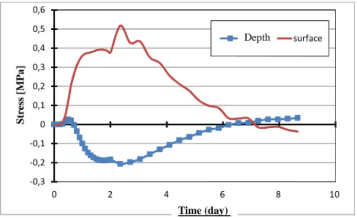
Then, the initial stresses in the Mock-up were calculated using the finite element software CAST3M, with a model incorporating temperature, hydration, shrinkage, creep and cracking. The parameters of this model have been identified in companion specimen tests in B11 concrete, representative of a nuclear power plant, which was used during the tests. A preliminary study has shown that drying induces only a localized surface cracking. Thus, this has not been taken into account in these calculations (there are formwork effects and the mesh must be fine enough).
-0,3 -0,2 -0,1 0 0,1 0,2 0,3 0,4 0,5 0,6 0 2 4 6 8 10 Co nt ra in te s[ M Pa ] Temps [jours] cœur surface S tr es s [M P a ] Time (day) Depth
Figure 6 - Time history of maximum stresses, in the depth and the surface of the concrete structure
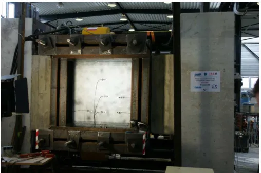
Mechanical behavior of the structure
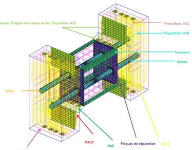
The Mock-up is loaded by six hydraulic jacks with a total capacity of 9000 kN, arranged in the soles into two groups of three jacks on the upper and lower parts. These jacks can be actuated by force or displacement. Coté aval 1 Débit d’air Coté amont 3 2 4 5 6
Supported by the soles, the jacks will put in tension the "zone of interest", thus creating cracks in this area. These correspond to cracks that may appear in a current containment wall area under ultimate pressure loads. After the creation of the cracks, the gas outputs through these cracks in the "zone of interest" are measured using an injection box (upstream side) and a recovery box (downstream side). Several sequences of measurements, at various injection pressure values upstream and at various crack apertures, are needed to cover the various flows through cracks that may appear in the containment wall during a severe accident.
Studies of the characteristics of these cracks, particularly their aperture, spacing and geometry, provide knowledge regarding the mechanical behavior of this area, particularly during the air-steam sequences. Studies of the leakage flow rates through the cracks provide knowledge about the assessment of containment building of nuclear power plants under loads of serious accidents. The displacement measurements are performed using 3 devices (Figure 8):
6 measurement sensors integrated into the hydraulic jacks
6 LVDT sensors with a stroke +/- 2mm, connected to the data acquisition system An image analysis system (DIC), for measuring displacement fields
Mechanical tests on the first Mock-up took place on July 4thand 5th2013 and then on March 12th
2014. On July 4th 2013, the Mock-up was put under tension by a force driven load using Digital
Image Correlation (DIC) to measure the displacement field.
Three levels were achieved at 20%, 40% and 60% of the theoretical rated load respectively, estimated from a direct tensile test on companion specimen. The 60% level was maintained long enough to observe the future cracks (processing of the displacement field from a few images) and to place 3 LVDT sensors on the future cracks observed from the displacement field. After the installation of the LVDT sensors, the Mock-up was fully unloaded before resuming the initial scenario, which allowed the aperture of the cracks created to be measured by both methods (DIC and LVDT). The scenario was completed respectively at 60%, 80% and 100% of the rated load prior to a second total unloading. During this loading, three cracks appeared in the "zone of interest". First, a crack at the center of the area, followed by two other cracks on either side of the first one, which reflects the proper control of the cracking process provided by the experimental device.
On July 5th2013, the Mock-up was put under tension again. First, having again been subjected to
a force driven load with 5 levels: (from 20% to 100% of the rated load), for the gas permeability testing. During this phase, the Digital Image Correlation (DIC) and the LVDT sensor data were not available. The downstream recovery box was dismantled during the 100% level, and the 6 LVDT sensors were installed. The Mock-up was then unloaded and reloaded with a displacement driven loading at a speed of 0.17 mm/min with several levels and a final ramp towards the estimated theoretical aperture of 500 µm. When a 4200 kN load was reached, a cracking sound was heard by the experimenters and the Mock-up was then unloaded. During this second load phase, DIC measurement was performed.
On March 12th2014, the Mock-up was put under tension with a displacement driven load. During
this loading, up to a 2 mm displacement of the jacks, the drive proved ineffective because of the failure of a jack sensor. The Mock-up was then unloaded and reloaded with a force driven load with increasing displacement target values until a displacement of 4.2 mm per jack was achieved. DIC measurement was performed during these two loading phases on the upstream side. LVDT sensors were placed on the downstream side in order to measure the cumulative apertures of the cracks and to easily find this displacement mark for measuring the leakage rate.
Analysis of the cracks was performed in two stages:
Displacement measurement by digital image correlation using the CORRELIQ4 software Crack analysis by Gaussian deconvolution of the displacement fields with a program
and the total strain. The processed images are synchronized with the mechanical load data (force sensors, jack displacement sensors and LVDT sensors).
Figure 9 shows the apertures of the residual cracks measured by LVDT sensors and calculated
from the displacement field at the end of the test (July 5th2013)
Figure 9 - Residual displacement field at the end of the test (July 5th, 2013)
Numerical simulation of the test, in particular of the step performed on July 4th 2013, allows to
understand the distribution of forces in the Mock-up. The use of the OTTOSEN fictitious crack constitutive model, developed with the CAST3M software, makes it possible to simulate the nonlinear behavior of concrete and the forces distribution in the structure. The cracking observed is found by this analysis, namely: a straight central crack occupying the entire section of the "zone of interest", with two parallel cracks located on either side, at about a third of the half-length of the study area, starting from each chamfer. The cracking also develops at the junction of the "zone of interest" with the self-compacting concrete (SCC), as well as at the corners, at the junction between the bearing portion of the soles and the brackets.
Non-linear calculations show the existence of several vertical, horizontal and traversing cracks occupying the entire section of the "zone of interest", which is the objective sought.
Figures 10 and 11 show the Mock-up and the layout of the cracks in the Mock-up. However, given that this Mock-up does not allow the direct measurement of the actual aperture of the cracks, the use of Mock-ups at a finer scale is needed.
Figure 10. Modeling used for the calculations
Figure 11. Layout of the cracks in the Mock-up
Study of the containment
The leakage rates through the cracks are measured using a tracer gas dilution method. This method consists in injecting helium at a controlled flow rate into the pressurized upstream box and collecting the helium-air mixture in the measurement box next to the wall on the downstream side of the Mock-up.
The helium concentration of the mixture collected downstream is then measured by means of a mass spectrometer, which allows the leakage rate from the crack to be known by continuously recording the helium balance in an open system.
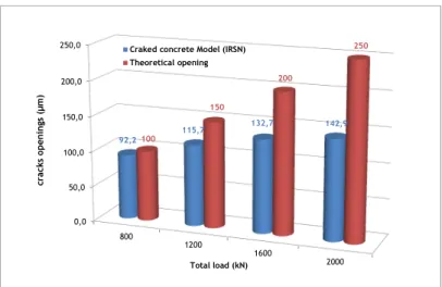
The crack aperture is obtained from the measured flow rate using a "Cracked Concrete Model" developed by IRSN. This model makes it possible to calculate the dimensional characteristics
(airflow opening) of a network of cracks, if the flow rate and associated pressure values are known. This model is explained in [3].
From the flow rate results obtained for Mock-up (Model 1), we have determined the cracks openings compared to the expected theoretical values. (Figure 12).
0,0 50,0 100,0 150,0 200,0 250,0 800 1200 1600 2000 92,2 115,7 132,7 142,9 100 150 200 250 cr ac ks op en in gs (µ m ) Total load (kN) Craked concrete Model (IRSN) Theoretical opening
Figure 12 - Cracks openings as a function of the total load applied by the jacks
Conclusion
The experimental program of the ECOBA project on full-scale Mock-ups offers a valuable scientific tool for studying the effectiveness of containment of nuclear reactor buildings. Knowledge obtained from the test results and numerical models will be used by IRSN in nuclear safety assessments, to support its expert analysis of the leak-tightness of the inner containments wall of nuclear power plants.
The full-scale Mock-ups built at the École Centrale de Nantes were achieved despite their complexity under the conditions of university laboratories. To develop them, teams had to overcome many technical and technological problems. The complementary skills of the teams involved were a great help to find accurate solutions.
These problems have led to delays in the progress of the project. Issues include the choice of the design of the Mock-up, the test control and monitoring system, the complexity of the finite element calculations, the design of the leak measurement system and the construction of the upstream injection box and downstream recovery box.
The instruments used are similar to those implemented in the containments buildings of the nuclear power plants under operation. They have been improved by additional measurements, in
particular in regard to crack aperture measurements: vibrating-wire sensors, LVDT sensors, image correlation and airflow aperture method. The redundancy and diversity of the measurement methods make it possible to compare different values and validate the results more robustly. In the last experimental campaign, parasitic leaks appeared on the sealing surfaces placed on the upper and lower faces of the "zone of interest". This problem is currently being resolved, thus allowing the experimental program to continue.
The first test results are very interesting, especially the creation of cracks in the "zone of interest" that are similar to those found on real structures subjected to such stresses, as well as the corresponding air leakage flow rate values. All of this confirms the great interest of the project and the possibilities of assessing the sensitivity of the parameters affecting the leak-tightness of containment buildings of nuclear power plants.
References
[1] Aubernon C., Influence du chargement mécanique, de la température et du fluide percolant sur la perméabilité des bétons, thèse de doctorat de l’Université de Nantes, 4 octobre 2011.
[2] Briffaut M. (2010), Étude de la fissuration au jeune âge des structures massives : influence de la vitesse de refroidissement, des reprises de bétonnage et des armatures, thèse de doctorat de l’ENS de Cachan, 22 octobre 2010.
[3] Gélain, T., Vendel, J., Research works on contamination transfers through cracked concrete walls Nuclear Engineering and Design (238) 1159–1165, 2008.
[4] Hilaire A., Benboudjema F., Darquennes A., Berthaud Y., Nahas G., Modelling basic creep in concrete at early-age under compressive and tensile loading, Nuclear Engineering Design, 269, p. 222-230, 2014.
[5] Loukili A., Chopin, D., Khelidj A., Le Touzo, J.-Y., A new approach to determine autogenous shrinkage of mortar at an early age considering temperature history, Cement and Concrete Research, vol. 30, n°6, p. 915-922, 2000.
[6] N’Guyen T. D. - Apport de la modélisation mésoscopique dans la prédiction des écoulements dans les ouvrages en béton fissuré en conditions d'accident grave, thèse de doctorat de l’Université de Pau et des Pays de l'Adour, 10 décembre 2010.
[7] N’Guyen, T. D., Lawrence C., La Borderie C., Nahas G., A mesoscopic approach for a better understanding of the transition from diffuse damage to localized damage.” European Journal of Environmental and Civil Engineering (14) 751-776, June 2010.
[8] Medjigbodo S., Aubernon C., Darquennes A., Khelidj A., Loukili A., Effects of the air-steam mixture on the permeability of damaged concrete, Cement and Concrete Research, Vol. 54, pp 98-105, 2013