HAL Id: hal-02272912
https://hal.inria.fr/hal-02272912
Submitted on 28 Aug 2019
HAL is a multi-disciplinary open access
archive for the deposit and dissemination of
sci-entific research documents, whether they are
pub-lished or not. The documents may come from
teaching and research institutions in France or
abroad, or from public or private research centers.
L’archive ouverte pluridisciplinaire HAL, est
destinée au dépôt et à la diffusion de documents
scientifiques de niveau recherche, publiés ou non,
émanant des établissements d’enseignement et de
recherche français ou étrangers, des laboratoires
publics ou privés.
Interactive and Immersive Tools for Point Clouds in
Archaeology
Ronan Gaugne, Quentin Petit, Jean-Baptiste Barreau, Valérie Gouranton
To cite this version:
Ronan Gaugne, Quentin Petit, Jean-Baptiste Barreau, Valérie Gouranton. Interactive and Immersive
Tools for Point Clouds in Archaeology. ICAT-EGVE 2019 - International Conference on Artificial
Reality and Telexistence - Eurographics Symposium on Virtual Environments, Sep 2019, Tokyo, Japan.
pp.1-8. �hal-02272912�
Interactive and Immersive Tools for Point Clouds in Archaeology
Ronan Gaugne1 , Quentin Petit2, Jean-Baptiste Barreau3 and Valérie Gouranton2
1Univ Rennes, Inria, CNRS, IRISA, France 2Univ Rennes, INSA Rennes, Inria, CNRS, IRISA, France
3Univ Rennes, CNRS, CReAAH, France
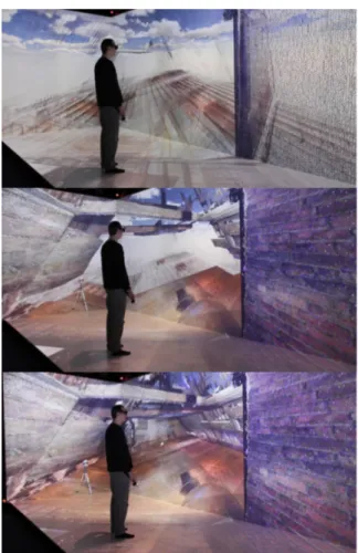
Figure 1: The immersive environment designed in an archaeological context enables navigation in large and dense point clouds (left) and interactions with the data such as cross-sections manipulation through a tracked tablet (center and right)
Abstract
In this article, we present a framework for an immersive and interactive 3D manipulation of large point clouds, in the context of an archaeological study. The framework was designed in an interdisciplinary collaboration with archaeologists. We first applied this framework for the study of an 17th-century building of a Real Tennis court. We propose a display infrastructure associated with a set of tools that allows archaeologists to interact directly with the point cloud within their study process. The resulting framework allows an immersive navigation at scale 1:1 in a dense point cloud, the manipulation and production of cut plans and cross sections, and the positioning and visualisation of photographic views. We also apply the same framework to three other archaeological contexts with different purposes, a 13th century ruined chapel, a 19th-century wreck and a cremation urn from the Iron Age.
CCS Concepts
• Human-centered computing → Virtual reality; • Applied computing → Archaeology;
a photogrammetry [BBST11], [AAA∗16], DICOM (Digital Imag-ing and COmmunications in Medicine) data in the case of a CT scan [MDG08], [RCD∗15] or point clouds in the case of a LiDAR (Light Detection And Ranging) scanner [LKH∗10].
In the case of digitization, such as laser scan or photogram-metry, meshes generation is based on mathematical computations on source raw data, using various algorithms such as Poisson [KBH06], extended marching cubes [KBSS01], or implicit smooth surface [SYM10] reconstructions. This data processing introduces approximations, with the creation of polygons representing aver-ages of sets of points, and errors, with the creation of surfaces be-tween points that are not linked in reality.
1. Introduction
Throughout the last decade, Cultural Heritage, and in particular ar-chaeology, has benefited from the extensive use of 3D technolo-gies, essentially focusing on reconstitution from modeling or scan-ning [NPMd12]. Many monuments, buildings and cities were given a new digital existence. Associated with virtual reality and aug-mented reality technologies, these reconstitution allow us to visu-alize, simulate and even interact with the past. Virtual reality com-bined with 3D digitization allows to immerse archaeologists in 1:1 copies of monuments and sites. Most of the time, the graphical en-vironment for these reconstitution is constituted of meshes gener-ated from digitization raw data that can be photos, in the case of
Ronan Gaugne & Quentin Petit & Jean-Baptiste Barreau & Valérie Gouranton / Point clouds in Archaeology
A point cloud is the basic raw data obtained when digitiz-ing archaeological sites with laser scans. These data represent a rich and faithful record provided that they have adequate tools to exploit them. They can serve as support for the modelling by snapping edges on existing points [CDD∗17] and their rep-resentation allows to distinguish themselves from a hypotheti-cal modelled by geometries [BBP∗14]. They can also be used in BIMs (Building Information Model), without being systemat-ically converted in meshes [ALT15]. More recently, they were use for artistic projects in Cultural Heritage context, as this kind of representation constitutes an aesthetic representation with fi-nesse and fragility of the real world [CMM∗18] or the Palimpsest project http://www.interactivearchitecture.org/ lab-projects/palimpsest.
In this paper, we propose a framework to handle point cloud data in immersive VR, for archaeological purposes.
2. Related works
Digital point cloud-like data is already widely used in other fields such as medicine, industry, and Geosciences. Each of these areas has its own specificity in their exploitation and use, whether for pathology detection in medicine [AIG∗14], quality control in in-dustry [WMN∗13], or erosion monitoring in Geosciences [LBL13]. It is therefore essential to provide tools adapted to the specific needs related to the field of archaeology. Archaeological material in a context of excavation, restoration or conservation, is gener-ally fragile and any intervention on its structure may damage or even destroy it. This statement fully justifies its systematic digi-tization, especially endangered material, whether due to climatic, geological or political conditions. Another particular aspect is the uniqueness of the study in archaeological context. It is difficult to provide systematic tools as in medicine and industry where situa-tions of study are essentially repetitive and reproducible. Further-more, in archaeological context, the case studies are largely based on interpretations and the expression of hypotheses and therefore leave an important part to the archaeologist. It is therefore essen-tial to propose environments in which the archaeologist can project himself/herself and use his/her own perception of a context. This is why the virtual reality that allows to immerse the user in 3D, scale 1, and offer customized interactions, is an interesting answer.
One important challenge is the display of point clouds that can be very large with hundred millions or even billions of points, and cannot benefit from the traditional rendering techniques for 3D meshes. Different approaches have been proposed to display large point clouds by structuring the data [GEM∗13], [SW11] or by applying rendering optimization techniques [PGK02]. These ren-dering tools are designed for visualization and manipulation on a single PC. They generally require software skills to use and can create ambiguities regarding the architectural dimensions. Recent works explored the rendering of large point clouds with immer-sive first-person view [PMM∗17] or in immersive display struc-tures [BSN14], [TBP15]. However, these works focus on the ren-dering and do not propose interactive tools or limited ones.
The work presented in [KBK08] describes an applica-tion to visualize LiDAR point cloud data in a CAVE, in
a geological context, for quality control, and extraction of survey measurements. The tools developed by the pri-vate company Octarina (http://www.octarina.com/ creating-content-experiences-vr-ar/) also pro-pose an interactive environment to manipulate point clouds in a VR headset, in industry context. These two works represent interesting illustrations of the value of immersive point cloud interactions in these two domains. Unfortunately, the proposed interactions are not relevant for archaeological purposes. The work presented in [KKB∗] proposes very interesting interactive tools for collaborative work sessions on a multi-user stereoscopic power wall and a tactile table, applied to very large point clouds obtained from laser scans of a large Cultural Heritage site in Italy. The interactive tools, dedicated to archaeology, are oriented to multiple users sessions for the analysis of the digital data. However, they do not propose a scale 1:1 immersion within the data.
3. Motivation of the work
Our work contributes with an interactive framework in immersive VR, based on point cloud data, designed specifically to answer ar-chaeological questions. The objective of the study is to explore and illustrate the interest for archaeologists, and more generally Cul-tural Heritage stakeholders, of manipulating point cloud data in an immersive environment. For this purpose, archaeologists were as-sociated all along the project in order to design, test, and validate different tools to help them in their scientific research.
Our work was performed in the context of a multidisci-plinary collaboration between archaeologists and computer scien-tists started several years ago, with the aim to propose and design new tools and new practices for archaeologists, based on 3D tech-nologies. The work was mainly driven by questions raised by ar-chaeologists during the study of a particular building, an ancient Real Tennis court.
3.1. Archaeological context
The building concerned by the study was built at the beginning of the 17th century. It was originally a Real Tennis court, but was transformed into a religious chapel at the end of 17th century, and became property of the army after the French revolution at the end of 18th century [FE15]. It is still in elevation and the municipality that owns it since 20th century asked for an archaeological diag-nostic in 2014, including a full digitization of its inside and outside (see Figure2), before launching rehabilitation works. The diagnos-tic was performed in few weeks, in parallel of the digitization with LiDAR, due to time constraints imposed by the municipality.
In order to pursue their study once the access to the building was no more possible, archaeologists asked computer scientists to propose an application based on the 3D data obtained during the digitization campaign. They needed to understand and document the evolution of the structure of the building. This requires a good representation of the actual volumes, an access to the internal or-ganisation and evolution of the walls and floors, and a highlight of particular details such as the clues of removed structures or recov-ering of ancient paintings. In order to fulfill these expectations, they
Figure 2: Point cloud of the Real Tennis building.
requested to be immersed in the digital record of the building, with specific functionalities:
• 1:1 high definition immersion. The first requirement from ar-chaeologists was of course to be able to navigate in the digital copy of the building, at scale 1:1, with a resolution enough faith-ful and precise to enable further studies.
• segmentation of the information delivered by the 3D data. These segmentation are represented in the form of cross-sections, cutting plans, or orthophotos, and depend totally on the different archaeological questions. They are often performed by 3D specialists, often at once on a PC, with no possibility for the archaeologist to superimpose and / or modify them au-tonomously, due to lack of training on these software, sometimes not very intuitive or expensive.
• linking between the 3D environment and 2D documentation, in particular photos taken during the diagnostic. These pho-tos represent an important amount of data and it can be interest-ing to associate the view of some details highlighted by photos with the gloal 3D data.
Other standard tools such as distance measurement, snapshots of the current point of view, or 3D models integration were also re-quested by archaeologists.
3.2. Contribution of the work
The contribution of our work is a VR application that aims to as-sist the archaeologists in their process of study, according to their needs. It consists in:
• an immersive VR application dedicated to archaeologists with a display of the dense point cloud at scale 1:1. We chose to work with a point cloud, because it represents the raw data obtained with the laser scan, exempt of any geometrical transfor-mation. However, this kind of 3D data implies some constraints to be used in a VR system, for an archaeological purpose. In particular, the point cloud must be dense enough to allow the ar-chaeologist to observe relevant information. The application was deployed in a CAVE-like structure, to allow the archaeologist to be physically present in the simulation and to have a better per-ception of the scale (see Figure3).
• a tracked tactile tablet to manage an interactive system of segmentation able to generate cross-sections, cutting plans and orthophotos. We chose this kind of interface as archaeolo-gists often use tactile tablets to record notes in their day to day
Figure 3: Immersive navigation in the point cloud in a large CAVE-like structure.
work, and to provide a tangible interaction with the virtual en-vironment that intuitively carry the position of a segmentation plan. The segmentation is defined by the plan colocated with the tablet within the framework, and the the current segmentation is visible on the screen of the tablet (see Figure1, center and right). Tactile interactions on the tablet allow to parameterize the segmentation and to generate the 2D renderings.
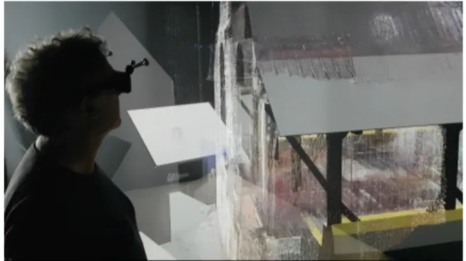
• a functionality of 2D photos and point of view interactive po-sitioning and activation inside the VR application. The user has the possibility to upload photos within the VR application and to position and scale them in the 3D environment (see Fig-ure4, Top). Once a photo is positioned, the user can define an
Figure 4: Top: Positioning of a photo within the VR application. Bottom: A floating sphere indicates a point of view of a photo in the application.
Ronan Gaugne & Quentin Petit & Jean-Baptiste Barreau & Valérie Gouranton / Point clouds in Archaeology
associated point of view materialized with a sphere. The photo will only be visible when the user’s head is co-located with the sphere (see Figure4, Bottom).
Additional features such as scaling, measuring, dynamic display configuration, and navigation complete the toolbox of the applica-tion. Technical details are presented in the next secapplica-tion.
4. Design and implementation 4.1. Point clouds production
The data used in this work were generated using a laser scan tech-nology. The scan of the Real Tennis building was performed in June 2014, with a Faro Focus3D X330. The resulting point cloud is con-stituted of 781 millions points with both inside and outside the cap-ture of the building (Figure 2). It was sampled to produce two point clouds, one high density point cloud (HDPC) for the close view with 240 millions points and one low density (LDPC) for the dis-tant view with 12 millions points.
4.2. Point cloud pre-processing
We used the binary Stanford Polygon format (PLY) for the point cloud. It has the advantage of being a compact and standard format supported by most of the 3D software. PLY files are structured as a list of (x,y,z) points coordinates that can also be enriched by the normal coordinates, (r,g,b) color values, and alpha property. The drawback of this format is that it is not designed to define a struc-ture or hierarchy between the points to help its loading, processing and rendering. In order to optimize the loading and rendering of the point clouds, we used an octree-based octree-based multireso-lution approach, using a method similar to [KBK08]. This kind of structure is common and well-known for point clouds. It allows to perform frustum culling on octree nodes to hide non-visible points using a top down traversal of the octree. The value of the threshold is defined in order to obtain a compromise between the number of draw calls, which depends on the size of the octree, and the frustum culling performance, which depends on the size of the leaves of the octree. The point cloud of the Real Tennis building is constituted of 5744 octree nodes including 4861 octree leaves.
In addition, a subsample is performed on each octree leaf by creating 3D voxel grid over the point cloud leaves (An example of the principle of the algorithm can be found at http://pointclouds.org/documentation/ tutorials/voxel_grid.php). The size of the voxel is user defined and induces grid size and point cloud density. In each voxel only the nearest point to the computed voxel centroid is kept. Each leaf of the octree is stored in a distinct binary file where points co-ordinates, colors and normals are contiguous in order to match the data sent to the GPU and reduce unnecessary processing overhead. All binaries files of the same resolutions are also packed into one big archive file, basically one file for HDPC and one for LDPC.
4.3. Point cloud processing 4.3.1. Architecture
The architecture of the application is designed in order to allow a distributed rendering of the VR part, on a cluster of PCs. Each PC
of the cluster runs several instances of the application. The appli-cation itself is built using 3D game engine Unity and applicative nodes are synchronized using MiddleVR, a VR plugin for Unity. In addition, the application allows the connection of client applica-tions, which can run on PCs or mobile devices, for specific views such as cross sections. Network clients’ connection and synchro-nization are dynamically managed with Unity Network component.
4.3.2. Point cloud loading
Two different modes can be used to load point cloud. The first mode reads archive files to store all points in RAM at the appli-cation startup in order to reduce I/O overhead and lead to better overall performance once point cloud is fully loaded. This mode is particularly useful when working in a distributed architecture, with a clustering mode where the overall performance depends of the worst node performance of the cluster nodes. The drawback of this mode is the limitation according to available RAM. The sec-ond mode reads single binary file to only load point clouds that are visible by the camera, in order to reduce RAM usage. This mode enables the handling of very large point clouds. The drawback of this mode is that it induces processing overhead during point cloud navigation.
4.3.3. Runtime display
One issue for the point clouds management is their graphical ren-dering as they cannot benefit from standard renren-dering optimization used for 3D surface-based data. We implemented adaptations of frustum culling and lod in order to gain performance on render-ing, so we can guarantee an acceptable frame rate for immersive and interactive visualization. Transition between HDPC and LDPC resolutions is done by comparing the distance from the user to the bounding box center to a given threshold that can be dynamically modified (see Figure5). These two techniques, level of detail and frustum culling, work well together on such data structure: at close range frustum culling discard a large number of points while at long range level of detail heavily reduce the number of points rendered.
4.4. Interactions with the point clouds
Various interactions are proposed to the user immersed in the point clouds. First interaction is naturally navigation, in a flying mode, using a tracked wand equipped with a joystick, with four degrees of freedom (translation in the direction pointed by the wand, rotation around the vertical axis).
Interactions with the point clouds are possible in two different ways. The first is through a radial menu used in the application, and controlled with the wand. The second is through a set of icons displayed on a tactile tablet connected to the application. The tablet interface is mainly used for cut plan manipulation.
4.4.1. Point clouds display properties
Points are rendered as a colored square composed of two triangles oriented to face the user like a billboard. Several configurations on the point cloud are proposed to the user. The size of the points can be changed for both LDPC and HDPC. Large point’s size leads to a uniform surface representation while a small point size highlights the structure of the current object with transparency rendering.
Figure 6: Cutaway manipulation.
pinpoint the position where the photo was originally taken. The placement of these views is manual and done through five 3D cubic handles on photos, on each corner and in the center (see Figure4). User can interact with the handles through a tracked controller ray cast; he can grab the photo through the center model and manip-ulate its position and rotation according to the initial distance be-tween controller and photo. Scale is also modifiable by dragging one of the corner models closer or further of the photo center. Dur-ing the manipulation, the photo is transparent in order to ease its po-sitioning. Once the position, rotation and scale of the photo match the point cloud they are saved in an external configuration file with the current user head position that represents the new sphere posi-tion. When the user puts his/her head inside the sphere, the photo becomes visible, and it disappears when the user quits the position of the point of view.
Figure 7: Integration of an outline inside the virtual environment.
This functionality can also be used to integrate 2D outlines in the 3D environment (see Figure7).
4.4.4. Scaling
User can modify the scale of the point clouds, either to increase the size of small objects, or to decrease the size of larger environments to get an overview. Scaling is calculated relative to the center of the bounding box of the point cloud using a homothetic transformation directly applied in the rendering shader for an efficient processing. Figure 5: Top: Low density point cloud. Middle: High density
point cloud close to the user, Low density at longer distance. Bot-tom: Full High Density point cloud.
4.4.2. Cross section and cutaway plan with tablet
A custom 3D marker placed on a tablet is used to manipulate a cut plane in our VR Cluster. This plane is used as a reference to hide points or make them semi-transparent in order to realize in real time, either a cross section, i.e. a parameterized thickness slice of the point cloud (see Figure 1, center), or a cutaway, i.e. a portion of the point cloud constituted of the points behind the cut plane (see Figure6, Top). A snap option can be enabled to force the plane to be horizontal or vertical when the plane angle is within a threshold. The tablet shows an orthographic view, orthogonal to the cut plan, of the cross section that can be saved at any time and exported as image. The view on the tablet is dynamically adjusted following its position in the virtual environment (see Figure 1, center). Configu-ration can be done through the tablet like changing the zoom level, adding a translation or rotation offset, or forcing the color of the points (see Figure 1, right).
4.4.3. Photographic viewpoints
Photographic viewpoints can be added to the point cloud as a com-plementary visualization tool. A sphere, textured with the associ-ated photo, serves as a landmark to locate this viewpoint and to
Ronan Gaugne & Quentin Petit & Jean-Baptiste Barreau & Valérie Gouranton / Point clouds in Archaeology
4.4.5. Mesh rendering
We can integrate other 3D data inside the VE like CAO 3D model or generated 3D model, that will be combined with the point cloud, to offer different level of information. Figure8shows the
integra-Figure 8: Superposition of the graphic modeling of the Real Tennis building.
tion of a graphic modeling of the Real Tennis court at the 18th cen-tury that was produced by the archaeologist in charge of the study. In this case, the 3D model was integrated and aligned within the development environment, but it is possible and easy to propose a runtime integration of 3D model, with an interactive positioning of the 3D model similar to the one used for positioning the photos.
5. Results and discussion 5.1. Results
5.1.1. Technical results
The resulting applications were deployed on a large CAVE-like fa-cility constituted of 4 screens, one floor of 9.6m x 2.9m, 6688px x 2000px two lateral screens of 2.9m x 3.1m, 2000px x 2160px, and a main vertical screen of 9.6m x 3.1m, 6688px x 2160px, with images displayed by 14 WQXGA laser projectors, driven by 7 PC, with the following characteristics: 2 Intel Xeon E5-2623v4 2.6 2133 4C, 32GB DDR4-2400, 2 NVIDIA Quadro P6000 24GB.
Each one of the seven PCs of the cluster runs two instances of the application, one for each projector. The tablet used for the in-teraction is a Microsoft Surface Pro 4, equipped with a tracking ge-ometry built with a 3D printer. Due to the clustering architecture, the overall performance is equal to the performance of the slow-est node. The performance on one node depends on the number of points displayed and the size of the points. For the largest point clouds, the Real Tennis building and the Chapel ruin, the perfor-mance varies from 10 FPS at full load to 60 FPS, which provides a fluent rendering of the point clouds. The application was also suc-cessfully deployed and run on a HTC Vive headset.
5.1.2. Archaeological results
Two archaeologists from outside the project evaluated the applica-tion in the large immersive facility. The first one pointed the interest of the 1:1 scale to better perceive the volumes and dimensions of the digitized contexts. He argued that the dimensions are very difficult
to evaluate on standard PC screens. He noted that the photographic views allowed to more easily make the connection with the real site. The second one was very enthusiastic about the cutting plan that produces 2D cut views, as this kind of documentation is intensively used when producing excavation reports, especially for buildings. Such 2D images are usually produced by IT technicians from spec-ifications given by archaeologists. In our application the real-time visualization of the 2D cut on the tablet allows the archaeologist to completely master his/her 2D cut and to easily explore alterna-tive 2D cuts during the immersive session. She also pointed out the interest of being immersed at 1:1 scale, in the case of the superposi-tion of the hypothetical modeling and the point cloud, to validate or detect incoherence in the hypothetical model. She also appreciated the high-density area and the point size management that provide a rendering close to a textured mesh. Finally, she noted the inter-est of such rendering to more easily share her understanding of the building, either in the context of an exchange with another expert, or in the context of scientific mediation, which is a very important activity of archaeology.
5.2. Instantiation to three other archaeological contexts We applied our work to three other archaeological contexts, cho-sen for their different states of conservation, complexity and ar-chaeological interest. (see Figure9, Top). The first context was a
Figure 9: Top: Cremation urn. Bottom, left: Wreck. Bottom, right: 13th century Chapel.
13th century ruined chapel, measuring 22m x 13m, with some pre-served elevations including the complete pinion with a rose win-dow and arcades. Beyond the classic interest of digital preservation of this unique architectural building [Gou73], the granite weath-ering due to the temperate oceanic environment [MPS08] acceler-ates the global erosion of the monument and motivated its digitiza-tion. The second context was an 18th-century wreck in a foreshore context, accessible at low tide [RPH∗18]. This context presents in-teresting characteristics encouraging a digitization project, with a limited size of the site (9m x 3m), a difficult access, as the wreck is under the sea most of the time, an endangered heritage, as the fore-shore context is highly destructive. The last context is a cremation urn of Iron Age discovered during an archaeological excavation of a necropolis, among a dozen urns [AL14]. The urns were all CT
5.3.2. Point clouds in VR
Some properties of point clouds have a significant impact on their usability in virtual reality. It is important that the point cloud is sufficiently dense and that the points are distributed evenly. The respect of these properties requires a good quality of the stage of digitization. As archaeology teams are increasingly trained in the use of digitization techniques, there is a clear improvement in the quality of point clouds produced, which favors the development of tools for handling this type of data.
Point clouds handling in VR requires to adapt the existing op-timization techniques used for 3D meshes. The two techniques we integrated, lod and frustum culling, allowed us to reach comfortable performance for the user with large size point clouds. Another opti-mization techniques such as occlusion culling could also be adapted to enhance the performances. But this particular technique requires a more complex handling, as the block of points can be transparent depending of the distribution of the points. Additional techniques such as [BWPP04] can be applied in this case.
The use of a CAVE by archaeologists is not always practical or possible, and it is difficult to envisage installing such facility in archaeology laboratories and museums. That is why we have also deployed our point cloud tools on an HMD. This kind of equipment is indeed more affordable and transportable and it is quite possible to include it in the panoply of an archaeological excavation site. However, in this case, the interaction modalities must be adapted, in particular for the manipulation of the cut plane by tablet which will have to be managed completely in the application environment of manipulation of the point cloud since the user does not have real-world visibility when wearing a helmet.
6. Conclusions
This paper presented a set of tools to manipulate point clouds in a highly immersive and interactive virtual reality environment, in an archaeological context. The tools were developed and evalu-ated on four different contexts, two buildings and one wreck digi-tized by LiDAR technology, and one cremation urn digidigi-tized by CT scan. The resulting application was successfully deployed in a large CAVE-like facility and was positively evaluated by two archaeol-ogists. The main functionalities of the application are a segmen-tation tool that allows to produce cross sections and cut-aways, a scaling tool, and an inlay tool that allows to position photographic views inside the point cloud. Further developments are underway to completely adapt the application to a more portable VR head-set context. The increasing use of digitization in Cultural Heritage context with the production of more and more digital data justify the development of adapted processing tools, especially around the point clouds which constitute a basic data in this field. Virtual re-ality, by immersing the user at 1:1 scale in these data is an in-teresting solution, especially by allowing to propose natural inter-actions to manipulate them. A video of this work is available at
https://vimeo.com/349679831
scanned, and the one presented in this paper revealed two interest-ing metal objects, a fibula and a knife blade.
The first two contexts represent two endangered sites that are in-teresting to document for comparative studies and general knowl-edge, but not enough interesting to justify an expensive restoration. In this case, a laser scan allows to perform a 3D recording of the sites that can be further studied using our framework. For both sites, 2D cuts were performed for archaeological documentation.
For the object-size context, the cremation urn, archaeologists found very interesting the change of scale to get inside the object and obtain an immersive navigation that allows a better understand-ing of the structure. In particular, they were able to follow the insect galleries between bones fragments and indicates that this could help to better understand the shifting of the fragments and re-associate some of them.
5.3. Discussion
5.3.1. Point clouds for archaeology
The digitization of archaeological material makes it possible to meet several objectives. First, a point cloud is a long-term, accu-rate record of the current state of the site, building, or object. This kind of recording is a major stake of the preservation of our Cul-tural Heritage. The numerical data obtained also makes it possible to document, study and argue. These data are often collected for a certain purpose, but as pointed out in [CBMM13], it is quite
pos-sible to reuse these data later with new objectives. Finally, a cloud of points constitutes an aesthetic data format that can be directly used in the scientific mediation framework, provided that tools are available to handle it.
The tools proposed as part of the work presented in this article have been designed to respond to actual needs of archaeologists. A work session around the point cloud of the chapel made it possible to easily and quickly generate cutting plans allowing documenta-tion of the monument subject to significant erosion. In the same way, the point cloud of the wreck is a working support that can be used while the real wreck, buried under 80cm of sand and covered by the sea most of the time, is very difficult to access. Cutting plans were also generated for this wreck and archaeologists noted that the generation of such cuttings was faster and more accurate than the usual hand-made drawings. The views of the urn and the change of scale have allowed archaeologists to have a unique and innova-tive view of its internal structure. The Real Tennis building was the richest source of data for the design and evaluation of point cloud manipulation tools. Several work sessions took place in the immer-sive environment and resulted in these first results. The fact that both the external and internal parts of the building were scanned, and that a 3D reconstitution of the original building was modeled by the archaeologist provided a rich amount of data source that is not always available. However, 3D digitization during archaeologi-cal excavations is more and more systematic and multi-source. It is thus important to be able to combine different kinds of data, either produced from different technologies such as LiDAR and CT scan, or of different nature, as in the combination of point cloud data, photographic views and surface meshes.
Ronan Gaugne & Quentin Petit & Jean-Baptiste Barreau & Valérie Gouranton / Point clouds in Archaeology
Acknowledgements
We would especially like to thank Yann Bernard and Florian Cousseau for the 3D scans done on the sites, Elen Esnault and Théophane Nicolas for their archaeological feedback.
References
[AAA∗16] ALFUGARAA., ALADAMATR., ALSHAWABKEHY., AL
KOURO., ALSHABEEBA. R.: A multi-resolution photogrammetric framework for digital geometric recording of large archeological sites: Ajloun castle-jordan. Int. Journal of Geosciences 7, 2 (2016), 425–39.1
[AIG∗14] ABEL. I., IWAOY., GOTOHT., KAGEIS., TAKIMOTOR. Y.,
DE SALES GUERRATSUZUKI M., IWASAWAT.: High-speed point cloud matching algorithm for medical volume images using 3d voronoi diagram. In 7th Int. Conf. on Biomedical Engineering and Informatics (Oct 2014), pp. 205–210.2
[AL14] AUBRYL., LEPUIL-TEXIERM.: Un enclos funéraire de l’âge du Fer, Domaine La Bizaie, Guipry, (France). Tech. rep., Inrap, 2014.6
[ALT15] ACHILLEC., LOMBARDININ., TOMMASIC.: Bim and cul-tural heritage: Compatibility tests in an archaeological site. In Building Information Modelling (BIM) in Design, Construction and Operations (2015), vol. 149, pp. 593–604.2
[BBP∗14] BARREAUJ.-B., BERNARDY., PETITQ., BEUCHETL., PE
-TITE., PLATENV., GAUGNER., LERUMEURJ., GOURANTONV.: Combination of 3D Scanning, Modeling and Analyzing Methods around the Castle of Coatfrec Reconstitution. In Int. Conf. on Culturage Her-itage, EuroMed(Lemessos, Cyprus, Nov. 2014), pp. 418 – 426.2
[BBST11] BARAZZETTI L., BINDA L., SCAIONI M., TARANTO P.: Photogrammetric survey of complex geometries with low-cost software: Application to the g1 temple in myson, vietnam. Journal of Cultural Heritage 12, 3 (2011), 253 – 262.1
[BSN14] BRUDERG., STEINICKEF., NÜCHTERA.: Poster: Immersive point cloud virtual environments. In IEEE Symp. on 3D User Interfaces (3DUI)(March 2014), pp. 161–162.2
[BWPP04] BITTNERJ., WIMMERM., PIRINGERH., PURGATHOFER
W.: Coherent Hierarchical Culling: Hardware Occlusion Queries Made Useful. Computer Graphics Forum (2004).7
[CBMM13] CHAPMAN H., BALDWIN E., MOULDEN H., M.LOBB: More than just a sum of the points: Re-thinking the value of laser scan-ning data. In Visual heritage in the digital age, Ch’ng E., Gaffney V., Chapman H., (Eds.). London: Springer London, 2013, pp. 15–31.7
[CDD∗17] CEMOLI L., D’AURIA S., DE SILLA F., PUCCI S., STROLLO R. M.: Infographic Modeling Based on 3d Laser Survey-ing for Informed Universal Design in Archaeological Areas: the Case of Oppidum of the Ancient City of Tusculum. ISPRS Annals of Pho-togrammetry, Remote Sensing and Spatial Information Sciences(Aug. 2017), 259–264.2
[CMM∗18] CHAPMAN P., MITCHELL D., MCGREGORC., WILSON
L., RAWLINSONA.: Art of the Point Cloud. Wild Harbour publish-ing, 2018.2
[FE15] FERRETTER., ESNAULTE.: RENNES (35). 10-12 rue Saint-Louis : Les occupations de la parcelle 0234 de l’Antiquité à l’époque moderne ; Le jeu de Paume du Pélican. Tech. rep., Rapport de fouille, Bibliothèque numérique du Service Régional de l’Archéologie de Bre-tagne, num. 3168, vol. 2, 2015.2
[GEM∗13] GOSWAMIP., EROLF., MUKHIR., PAJAROLA R., GOB
-BETTIE.: An efficient multi-resolution framework for high quality in-teractive rendering of massive point clouds using multi-way kd-trees. The Visual Computer 29, 1 (Jan 2013), 69–83.2
[Gou73] GOULETQUERP.-L.: PLOVAN. Kergalan. rapport de fouille programmée. Tech. rep., Service régional de l’archéologie de Bretagne, http://bibliotheque.numerique.sra-bretagne.fr/items/show/1238, 1973.6
[KBH06] KAZHDANM., BOLITHOM., HOPPEH.: Poisson surface re-construction. In Proceedings of the Fourth Eurographics Symposium on Geometry Processing(Aire-la-Ville, Switzerland, Switzerland, 2006), SGP ’06, Eurographics Association, pp. 61–70.1
[KBK08] KREYLOSO., BAWDENG. W., KELLOGGL. H.: Immersive visualization and analysis of lidar data. In Advances in Visual Comput-ing(2008), Bebis G., Boyle R., Parvin B., al., (Eds.), Springer Berlin Heidelberg, pp. 846–855.2,4
[KBSS01] KOBBELTL. P., BOTSCHM., SCHWANECKEU., SEIDEL
H.-P.: Feature sensitive surface extraction from volume data. In Proc. of the 28th Annual Conf. on Comp. Graphics and Interactive Techniques (New York, NY, USA, 2001), SIGGRAPH ’01, ACM, pp. 57–66.1
[KKB∗] KULIK A., KUNERT A., BECK S., MATTHES C.-F., SCHOLLMEYER A., KRESKOWSKI A., FRÖHLICH B., COBB S., D’CRUZM.: Virtual valcamonica: Collaborative exploration of prehis-toric petroglyphs and their surrounding environment in multi-user virtual reality. Presence: Teleoperators and Virtual Environments 26.2
[LBL13] LAGUED., BRODUN., LEROUXJ.: Accurate 3d comparison of complex topography with terrestrial laser scanner: Application to the rangitikei canyon (n-z). ISPRS Journal of Photogrammetry and Remote Sensing 82(2013), 10 – 26.2
[LKH∗10] LOBBM., KRAWIECK., HOWARDA. J., GEAREYB. R., CHAPMAN H. P.: A new approach to recording and monitoring wet-preserved archaeological wood using three-dimensional laser scanning. Journal of Archaeological Science 37, 12 (2010), 2995 – 2999.1
[MDG08] MUSTRAM., DELACK., GRGICM.: Overview of the dicom standard. In 2008 50th International Symposium ELMAR (Sep. 2008), vol. 1, pp. 39–44.1
[MPS08] MAGRÉG., PARISR., SELLIERD.: Évaluation de la météori-sation du granite en milieu tempéré océanisé à partir de monuments his-toriques en Bretagne méridionale. Tech. rep., Bulletin de l’Association de Géographes Français, 2008, vol. 85, no 1, p. 71-82, 2008.6
[NPMd12] NÚÑEZA. A., POZUELOF. B., MARIMÓNJ. R.,DEMESA
GISBERTA.: Generation of virtual models of cultural heritage. Journal of Cultural Heritage 13, 1 (2012), 103 – 106.1
[PGK02] PAULYM., GROSSM., KOBBELTL. P.: Efficient simplifica-tion of point-sampled surfaces. In IEEE Visualizasimplifica-tion, 2002. VIS 2002. (Oct 2002), pp. 163–170.2
[PMM∗17] PALHA A., MURTIYOSOA., MICHELINJ.-C., ALBY E., GRUSSENMEYERP.: Open source first person view 3d point cloud visu-alizer for large data sets. In The Rise of Big Spatial Data (Cham, 2017), Ivan I., Singleton A., Horák J., Inspektor T., (Eds.), Springer Interna-tional Publishing, pp. 27–39.2
[RCD∗15] REA., CORSIJ., DEMMELBAUERM., MARTINIM., MILA
G., RICCIC.: X-ray tomography of a soil block: a useful tool for the restoration of archaeological finds. Heritage Science 3, 1 (2015), 4.1
[RPH∗18] RIETHÉ., POVEDAP., HULOTO., MARINEJ., BERTOLI
-ATTIS., LAVIERC.: L’épave du milieu du XVIIe siècle d’Erquy (Côtes-d’Armor) : archéologie d’une architecture navale vernaculaire. CAS Cahiers d’Archéologie subaquatique, 22 (Sept. 2018), 41–92.6
[SW11] SCHEIBLAUER C., WIMMERM.: Out-of-core selection and editing of huge point clouds. Computers Graphics 35, 2 (2011), 342 – 351. Virtual Reality in Brazil Visual Computing in Biology and Medicine Semantic 3D media and content Cultural Heritage.2
[SYM10] SALMANN., YVINECM., MERIGOTQ.: Feature preserving mesh generation from 3d point clouds. Computer Graphics Forum 29, 5 (2010), 1623–1632.1
[TBP15] TREDINNICKR., BROECKERM., PONTOK.: Experiencing in-terior environments: New approaches for the immersive display of large-scale point cloud data. In 2015 IEEE VR (2015), pp. 297–98.2
[WMN∗13] WELLSL. J., MEGAHEDF. M., NIZIOLEKC. B., CAME
-LIOJ. A., WOODALLW. H.: Statistical process monitoring approach for high-density point clouds. Journal of Intelligent Manufacturing 24, 6 (2013), 1267–1279.2