HAL Id: hal-01300880
https://hal-univ-rennes1.archives-ouvertes.fr/hal-01300880
Submitted on 31 May 2016
HAL is a multi-disciplinary open access
archive for the deposit and dissemination of
sci-entific research documents, whether they are
pub-lished or not. The documents may come from
teaching and research institutions in France or
abroad, or from public or private research centers.
L’archive ouverte pluridisciplinaire HAL, est
destinée au dépôt et à la diffusion de documents
scientifiques de niveau recherche, publiés ou non,
émanant des établissements d’enseignement et de
recherche français ou étrangers, des laboratoires
publics ou privés.
Saber Dakhli, Hatem Rmili, Jean Marie Floc’H, Muntasir Sheikh, Abdallah
Dobaie, Kourosh Mahdjoubi, Fethi Choubani, Richard W Ziolkowski
To cite this version:
Saber Dakhli, Hatem Rmili, Jean Marie Floc’H, Muntasir Sheikh, Abdallah Dobaie, et al.. Printed
multiband metamaterial-inspired antennas. Microwave and Optical Technology Letters, Wiley, 2016,
58 (6), pp.1281–1289. �10.1002/mop.29792�. �hal-01300880�
Abstract—A family of multiband metamaterial-inspired dipole antennas are reported. These antennas are based on a dipole integrated in a planar configuration with capacitively loaded loops (CLLs) as their near-field resonant parasitic (NFRP) elements. In the realized structures, the number of operating frequencies is determined by the size of the CLLs and their proximity to the printed dipole.. Simulation results explain the design features and demonstrate that the structures present a multiband behavior. Three corresponding prototypes were fabricated and tested. The measured impedance mismatch and radiation pattern results are presented and are shown to be in good agreement with their simulated values.
Index Terms—Capacitively loaded loop (CLL), metamaterial-inspired structures, multiband behavior, printed dipole antennas, radiation patterns.
I. INTRODUCTION
Metamaterials (MTMs) are characterized as exhibiting exotic physics behaviors and, as a consequence, they have been attractive for use in many electromagnetic engineering applications [1-3]. In particular, their material properties can be tailored to a given application. Several prototypes have been developed for radiating and scattering applications operating from UHF to optical frequencies. In contrast to bulk metamaterials, metamaterial-inspired structures are those that are based on one or a few metamaterial unit cells. They have provided extremely interesting flexibility in the engineering design process for manipulating a variety of electromagnetic, acoustic and thermal wave phenomena. A number of metamaterial-inspired electrically small antenna (ESA) designs, emphasizing high efficiency, high directivity and large bandwidth have been realized. The concept of metamaterial-based antennas was proposed in the early 2000’s [4], [5]. The paradigm of metamaterial-inspired
electrically small antennas was introduced in [6]. A variety of examples of these types of antennas have been reported [7]-[11]. Reviews describing the progress of recent applications of metamaterials to antennas have appeared recently [12], [13].Additional studies have reported configurations that are low profile and operate at low frequencies [14], have multi-functionalities [15], and have high directivities [16]. Recent considerations have emphasized the inclusion of active non-Foster (NF) elements in these near-field resonant parasitic (NFRP) antenna designs to achieve several interesting electrically small antenna properties simultaneously, including broad impedance and directivity bandwidths [17]-[18]. These NF designs were integrated together to achieve an efficient, high directivity, large front-to-back ratio, and wide impedance and directivity bandwidth, electrically small antenna [19]. Active unit cells have been of great research interest for low loss and broad-bandwidth metamaterials from low to very high frequencies [20]-[22].
In this paper, we report printed planar multiband metamaterial–inspired antennas that are based on the compact augmentation of a driven dipole antenna with two capacitively loaded loop (CLL) elements. Single [23]-[25] and multiple [26], [27] CLLs have been used previously as NFRP elements to successfully control the radiation patterns of printed monopole antennas at one and several frequencies. The CLLs are simpler metamaterial unit cells than their split-ring resonator (SRR) counterparts that have been used in similar applications, e.g., [28], [29].. This work represents an extension of the results presented in [30]; it includes a more complete analysis of the design features of the antenna and improved experimental results. In particular, it will be shown that the addition of the CLLs leads to the desired multi-frequency behavior and depends simply on their size and their proximity to the printed dipole.
Saber Dakhli
1,Hatem Rmili
2,Jean-marie Floc’h
3, Muntasir Sheikh
2, Abdallah Dobaie
2, Kourosh Mahdjoubi
1,
Fethi Choubani
4and Richard W. Ziolkowski
51IETR, University of Rennes 1, Campus Beaulieu - bât.11D, #263, Av. Général Leclerc, CS 74205, 35042 Rennes Cedex, France. [email protected]
2King Abdulaziz University, Electrical and Computer Engineering Department, P.O. Box 80204, Jeddah 21589, Saudi [email protected] ; [email protected] ;[email protected]
3IETR, INSA, 20 avenue buttes des coësmes, 35043 Rennes, France. [email protected]
4Innov’Com Laboratory, SUPCOM, University of Carthage, Tunis, Tunisia. [email protected] ; [email protected]
5Department of Electrical and Computer Engineering, University of Arizona, 1230 E. Speedway Blvd., Tucson, AZ, 85721, USA [email protected]
Printed Multiband Metamaterial-Inspired
Antennas
II. BASIC STRUCTURE
A printed dipole antenna was selected as the driven element and the two CLLs were selected as the NFRP elements because they could be very simply integrated with it. The resulting NFRP antenna was fabricated with a Rogers DuroidTM 5880 substrate with thickness 0.8 mm, relative permittivity 2.2, relative permeability r = 1.0 and loss tangent equal to 0.0009. The structure was simulated by using the ANSYS/ANSOFT high frequency structure simulator (HFSS).
A. Printed dipole antenna design
As shown in Fig.1, the printed dipole is constructed in a three layer fashion. One dipole arm and the positive microstrip feed-line connected to it are printed on the top side of the substrate. The second dipole arm and the negative microstrip feed-line connected to it are printed on the bottom side. A ground strip near the feed point of the structure on the bottom side is combined with the negative feed-line.
(b)
Figure 1: Geometry of the basic structure (dimensions in millimeters).
The two arms have a total length L, which was selected to be L = 50 mm. The distance D between the arms and the ground plane influences the antenna impedance matching. The ground strip length was chosen to be 66 mm, slightly larger than L, in order for it to act as a reflector, concentrating the radiated power into the front, broadside direction (θ = 0°). The width of the ground strip (6 mm) and the width of its feed-point portion (15 mm) were selected to accommodate the SMA connector and for ease of fabrication. With an optimized distance D= 34 mm, between the dipole arms and the ground strip, the antenna operates at 2.45 GHz in the ISM band without any additional matching network. The details of the design are given in Fig. 1. B. Simulation results
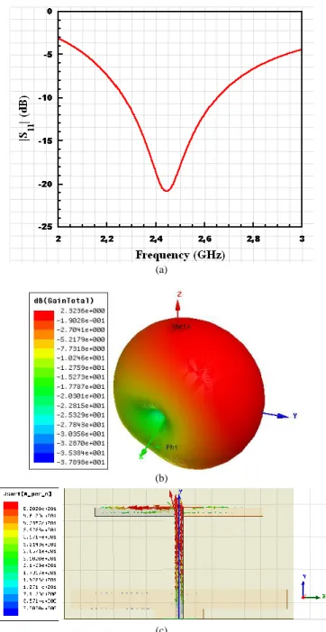
The simulated performance characteristics of this printed dipole radiator are summarized in Fig. 2. The input impedance mismatch values as a function of the excitation frequency are given in Fig. 2(a). It shows that the resonance frequency is 2.45GHz with a 10dB fractional impedance bandwidth approximately equal to 19%. Fig. 2(b) presents
the 3D-radiation pattern of the antenna at its resonance frequency, 2.45GHz. It clearly shows a dipole-like pattern with its null along the X-axis and with a maximum towards the positive Y-direction. The maximum gain is 2.32dB. This value is slightly larger than expected from a small dipole because of the presence of the ground-strip reflector, which slightly reduces the back radiation from the radiator while enhancing its forward value. The distribution of the surface current vectors on the copper of the antenna at 2.45 GHz is illustrated in Fig.2(c). While the current is large along the Y axis on the positive feedline, the associated radiated field is cancelled by the field created by the opposite flowing current on the negative feedline. The currents that create the dipole pattern shown in Fig. 2(b) are dominated by the contributions from the arms and the ground strip.
(a)
(b)
(c)
Figure 2: Simulation results of the basic printed dipole structure. (a) Input
impedance mismatch values, |S11| (dB), versus the excitation frequency
show the resonance frequency is 2.45 GHz;(b) 3D-gain pattern and (c) surface current distribution at this resonance frequency.
III. ANTENNAS WITH TWO CLLNFRPELEMENTS
In order to obtain a multi-band behavior, we have added two printed CLL elements to the structure, one on each side of the substrate to be coupled to the associated dipole arm and feedline as depicted in Fig. 3. As proved in previous works [23], [24], the presence of a CLL element close to a driven dipole antenna generates a second resonance at a frequency lower than the driven element. This effect reduces the effective overall size of the antenna, which improves its miniaturization [23], [24]. In our case, two CLL NFRP elements have been added close to the segments of the dipole antenna where the highest surface currents are localized. This significantly increases the coupling between the CLL elements and the driven dipole.
A. Optimized structures
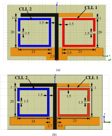
We have studied two configurations: the first structure shown in Fig 3(a) denoted A1 consists of two identical, symmetrically located (with respect to the microstrip line) CLL elements. The second antenna, denoted A2, is shown in Fig. 3(b). It consists of two CLL elements having slightly different sizes and placements with respect to the microstrip line. The configurations were optimized to achieve good impedance matching to a 50 source.
(a)
(b)
Figure 3: Geometry and dimensions (in millimeters) of the multiband
antenna structures. (a) Antenna A1, and (b) antenna A2.
It must be noted that configuration A2 was obtained from configuration A1 after an extensive parametric study which took into account the main design parameters and optimized the structure to achieve the lowest operating frequencies with good impedance matching. It was found that the main parameters affecting these two main properties are the
dimensions of the CLLs and the coupling distance between them and the feed line.
B. Simulation results
1- Impedance matching
The simulated |S11| values of these two mutli-band antennas as a function of the source frequency are plotted in Fig. 4.As shown in Fig.4 (a), antenna A1 is characterized by a single low resonance frequency at 1.61GHz, in addition to the dipole resonance at 2.17GHz. This single, low frequency resonance result is due to the fact that both CLLs are identical and symmetrically located with respect to the driven dipole and, therefore, resonate at the same frequency. On the other hand, in the case of antenna A2, where the two loops are sized differently and are asymmetrically positioned, Fig. 4(b) shows that two different low frequency resonances are obtained, at 1.52 and 1.62 GHz, in addition to the dipole resonance at 2.20GHz. These low frequency resonances are related to the size of each CLL element and to its level of coupling to the dipole, as well as its coupling to the other CLL element. The coupling is controlled by the distances the CLL elements are from the driven dipole and each other. In Fig. 4(b) the larger sized CLL element gives the 1.51 GHz value and the different distance to the dipole of the same-sized CLL element slightly shifts the corresponding resonance frequency from 1.61 to 1.62 GHz. The asymmetric coupling of the two CLL elements, particularly the close proximity of the same-sized one to the dipole element, lowers the dipole resonance. By varying their sizes and the coupling distances, the various resonance frequencies can be tuned to desired values. (a) CLL 2 CLL 1 20 20 23 23 2.5 2.5 1.5 1.5 1.5 1.5 1 1 20 1.5 1.5 1.5 1.5 1 1 24 23 2.7 0.5 CLL 2 CLL 1
(b)
Figure 4: Simulated input impedance mismatch, |S11,| as a function of the
source frequency. (a) Antenna A1, and (b) antenna A2.
2- Surface currents
In order to analyze the origin of these resonances, we have studied the distribution of the surface currents on the copper elements for both structures. Fig.5 illustrates the simulated surface current distributions for antennas A1 and A2 at their resonance frequencies. From Fig. 5-a, it is verified that the lowest frequency resonance at 1.61 GHz corresponds to the simultaneous resonance of both CLL elements and that the highest one corresponds to the dipole resonance at 2.17GHz. Similarly, in Fig. 5-b, the lowest frequencies at 1.52 GHz and 1.62 GHz correspond to the larger (left) and the same-sized (right) CLL elements, respectively. The resonance at 2.20 GHz clearly shows the dipole behavior. Notice that when each of the structures is resonant, the others are not. Again, this indicates that each of the resonance frequencies could be tuned without impacting the other ones.
f1= 1.61 GHz f2= 2.17GHz (a) f1= 1.52GHz f2= 1.62 GHz f3= 2.20 GHz (b)
Figure 5: Simulated surface current distributions for the two proposed
antennas at their resonance frequencies. (a) Antenna A1, and (b) antenna A2.
3- Radiation patterns
The simulated gain patterns of antennas A1 and A2at their resonance frequencies are presented in Fig. 6. These patterns closely correspond to the behavior expected from the current distributions shown in Fig. 5. Fig. 6(a) shows that antenna A1 acts as a pair of magnetic dipoles at the low frequency 1.61 GHz that are oriented along the z-axis, i.e., they result from the loop modes excited in the CLL elements as illustrated in Fig. 5(a). The pattern has its maximum gain in the (x-y) plane. It also shows that antenna A1 acts as an electric dipole placed along x-axis at the higher resonance frequency, 2.17GHz, where the dipole element is resonant but the CLL elements are not. This pattern clearly corresponds to the reference dipole case shown in Fig. 2(b), which shows the modification of the dipole pattern by the presence of the ground strip.
f1= 1.61GHz f3= 2.17GHz (a) f1= 1.52GHz f2= 1.62GHz f3= 2.20GHz (b)
Figure 6: Simulated 3D gain patterns for the two proposed antennas
at their resonance frequencies. (a) Antenna A1, and (b) antenna A2.
The corresponding simulated gain patterns for antenna A2 at its resonance frequencies are given in Fig. 6(b). The antenna clearly acts as two independent, resonant magnetic
dipoles at the lower resonance frequencies, 1.52 and 1.62GHz. At 1.52GHz, the maximum gain is along the x-axis; at 1.62 GHz it is along the y-axis. At the higher resonance frequency, 2.20 GHz, it again acts as an electric dipole modified by the presence of the ground strip.
C. Experimental Validation
Prototypes of the two antennas, A1 and A2, were fabricated. Photos of them are shown in Fig. 7. They were characterized experimentally by measuring their impedance mismatch over the frequency band 1-3 GHz and their gain patterns at their resonant frequencies. The impedance mismatch, i.e., the |S11| values, as a function of the source frequency was measured using a network analyzer Agilent N5230A. The gain patterns were obtained in a “SATIMO Stargate32” anechoic chamber.
(a)
(b)
(c)
(d)
Figure 7 :Photos of the realized prototypes: antenna A1: (a) top view,
1- Impedance matching
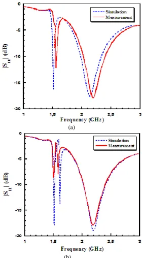
Fig. 8 compares both the simulated and measured |S11| values for antennas A1 and A2. As predicted, when the two CLLs are identical and symmetric, only two resonance frequencies are obtained as illustrated in Fig.8 (a). On the other hand, when the CLLs are asymmetrically located and have different sizes, three resonance frequencies are obtained as confirmed in Fig. 8(b).Fig. 8 confirms the multi-band behavior of the proposed structures. Resonances occur at frequencies 1.55 GHz and 2.18 GHz for antenna A1; and at 1.48 GHz, 1.59 GHz and 2.18 GHz for antenna A2. The agreement between the simulated and measured results is very reasonable given the fabrication tolerances.
(a)
(b)
Figure 8: Comparison of the measured and simulated input impedance
mismatch, |S11|, as a function of the source frequency.(a) Antenna A1, and
(b) antenna A2.
2- Radiation patterns
Fig.9 presents the 3D measured radiation patterns of the fabricated prototypes of the two antennas at their resonance frequencies. We can observe different shapes of the radiation patterns due to the different excited parts of the antenna A2. In fact, at the lowest frequency, 1.53GHz, the first CLL element (on the right in Fig. 3) is strongly excited and resonant; the antenna acts as a dipole oriented along the y-axis. At the frequency, 1.61GHz, the second CLL element (on the left in Fig. 3) is resonant. At this frequency, we note that the pattern is more directive along the +z-axis. In this
case, the structure behaves like a Huygens source in that the CLL element acts as a magnetic dipole in combination with the electric dipole. At 2.18 GHz, the electric dipole behavior is clearly dominant once again. In the case of the antenna A1 and at the lowest resonance frequency 1.58 GHz, the two CLL elements are simultaneously highly excited and visually act as a dipole perpendicular to the principal dipole. For the resonance occurring at 2.18GHz, the two CLLs are not resonating and their effects are disabled. The radiation pattern of the antenna is highly affected by the resonance of the principal dipole.
F1 = 1.58GHZ F2 = 2.18GHZ (a) F3 = 1.53GHZ F4 = 1.61GHZ F4 = 2.18GHZ (b)
Figure 9: Measured 3D gain patterns for the two proposed antennas
IV. ANTENNA WITH TWO NFRPCLLELEMENTS AND A
DIRECTOR ELEMENT
In order to generate an additional resonance frequency, a parasitic element is introduced. This geometry, included the additional director element, is shown in Fig. 10. This structure was based on the A2 antenna design optimized to generate a new higher frequency resonance.
A. Antenna design
The geometry and the parameters design of the antenna are shown in Figure 11. The dimensions of the dipole and the two CLLs are the same as the antenna A2.
Figure 10: Geometry and dimensions (in millimeters) of the multiband
antenna structure including a director element.
The new frequency F4 corresponds to the length λeff/2 of the parasitic element.
The prototype is fabricated and characterized. Fig. 11 presents photos of the realized prototype.
(a)
(b)
Figure 11: Photos of the realized prototype: (a) Top View; (b) Bottom
View.
B. Results and discussions 1- Impedance matching
Fig. 12 represents simulated and measured impedance mismatch for the proposed antenna. Again, the agreement between the measured and the predicted results is good.
Figure 12: Measured and Simulated input impedance mismatch, |S11| as a
function of the source frequency
We can remark from Fig. 12 that we have generated especially an additional resonant frequency higher than the monopole’s one. Simulations performed on the structure show multi resonant frequencies at 1.52 GHz, 1.61 GHz, 2.38 GHz and 3.65 GHz, while measurement gives resonances at 1.54 GHz, 1.63GHz, 2.25 GHz and 3.69 GHz.
2- Surface currents
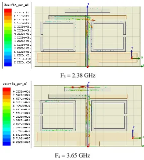
To investigate the origin of these resonances, we have studied the distribution of surface currents on the structure at two selected resonant frequencies. Fig. 13 represents the surface currents simulated at 2.38 GHz and 3.65 GHz.
F3 = 2.38 GHz
F4 = 3.65 GHz
Figure 13:Simulated surface current for the proposed antenna
At the frequency 2.38 GHz, only the dipole is active, the two resonators and the parasitic element are disabled, whereas the frequency 3.65 GHz corresponds mainly to the parasitic element excitation.
3- Radiation patterns
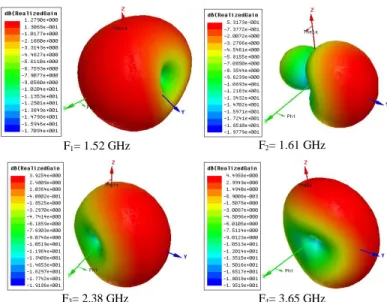
Fig.14 presents 3D simulated radiation patterns of the proposed antenna at its resonance frequencies. We can observe different shapes of radiation patterns due to the different excited parts of the antenna.
F1= 1.52 GHz F2= 1.61 GHz
F3= 2.38 GHz F4= 3.65 GHz
Figure 14: Simulated 3D-radiation patterns for the single NFRP element
reconfigurable antenna.
F1 = 1.54GHZ
F2 = 1.63GHZ
F3 = 2.25GHZ
F4 = 3.69GHZ
Figure 15: Measured 3D radiation patterns of the prototype single NFRP
element reconfigurable antenna. (a) State 1at fR = 1. 54 GHz and (b) State 2
at fR = 1. 63 GHz
In fact, at the lowest frequency 1.54 GHz, the first resonator element (on the right in Fig. 3) is strongly excited and acts as a dipole with a zero on y-axis. The frequency 1.63 GHz, corresponds to the resonance of the second resonator (on the left in Fig. 3). At this frequency, we note a directive beam toward +y-axis. In this case, the structure behaves like a Huygens source, where the CLL element acts as a magnetic dipole which is combined to the electric dipole.
The parasitic element and the two CLLs are disabled at the frequency 2.38 GHz. The resulting radiation pattern corresponds to the dipole one. Finally, the frequency 3.65 GHz, corresponds to the resonance of the parasitic element alone. The measured values of the maximum gain obtained for the proposed antenna are 0.87 dBi, 0.48 dB, 3.46 dB and 4.47 dB at frequencies 1.54 GHz, 1.63 GHz, 2.25 GHz and 3.69 GHz, respectively
V. CONCLUSION
In this paper, a class of multi-band metamaterial-inspired printed dipole antennas is reported. The structures consist of a principal dipole antenna associated with two CLLs parasitic elements in order to obtain supplementary resonances. Simulated and experimental results are in good agreement. These results show that placing CLLs and a parasitic element close to the printed dipole creates resonant frequencies depending on their size and proximity to the feeding line. In addition to the multifrequency behavior, the proposed antennas present different shape of radiation patterns due to the possibility to able or disable some parts of the structure as the dipole, the CLLs elements and the parasitic element.
These properties make the proposed antennas well suitable for some emerging multiband wireless applications.
ACKNOWLEDGMENT
This project was funded by the Deanship of Scientific Research (DSR), King Abdulaziz University, under grant No. (21-135-35-HiCi). The authors, therefore, acknowledge technical and financial support of KAU.
REFFERENCES
[1] N. Engheta and R. W. Ziolkowski, Eds., Metamaterials: Physics and
Engineering Explorations, IEEE Press, Wiley Publishing, Hoboken, NJ,
2006.
[2] G.V. Eleftheriades and K.G. Balmain, Eds., Negative-Refraction
Metamaterials Fundamental Principles and Applications, IEEE Press,
Wiley Publishing, 2005.
[3] C. Caloz and T. Itoh, Electromagnetic Metamaterials: Transmission Line
Theory and Microwave Applications, IEEE Press, Wiley Publishing, 2005.
[4] R. W. Ziolkowski and A. Kipple, “Application of double negative metamaterial to increase the power radiated by electrically small antennas,”
IEEE Trans. Antennas Propag., vol. 51, pp. 2626–2640, Oct. 2003.
[5] R. W. Ziolkowski and A. Erentok, “Metamaterial-based efficient electrically small antennas,” IEEE Trans. Antennas Propag., vol. 54, pp. 2113–2130, Jul. 2006.
[6] A. Erentok and R. W. Ziolkowski, “Metamaterial-inspired efficient electrically-small antennas,” IEEE Trans. Antennas Propag., vol. 56, pp. 691–707, Mar. 2008.
[7 ] D. H. Lee, A. Chauraya, Y. Vardaxoglou, and W. S. Park, “A compact and low-profile tunable loop antenna integrated with inductors,” IEEE
Wireless Propag. Lett., vol. 7, pp. 621–624, 2008.
[8] C. Caloz, T. Itoh, and A. Rennings, “CRLH traveling-wave and resonant metamaterial antennas,” IEEE Antennas Propag. Mag., vol. 50, pp. 25–39, Oct. 2008.
[9] M. A. Antoniades and G. V. Eleftheriades, “A broadband dual-mode monopole antenna using NRI-TL metamaterial loading,” IEEE Wireless
Propag.Lett., vol. 8, pp. 258–261, 2009.
[10] G. Mumcu, K. Sertel, and J. L. Volakis, “Miniature antenna using printed coupled lines emulating degenerate band edge crystals,” IEEE
Trans. Antennas Propag., vol. 57, pp. 1618–1624, Jun. 2009.
[11] J. Zhu, M. A. Antoniades, and G. V. Eleftheriades, “A compact tri-band monopole antenna with single-cell metamaterial loading,” IEEE Trans. Antennas Propag., vol. 244, pp. 1031–1038, Apr. 2010
[12] R. W. Ziolkowski, P. Jin and C.-C.Lin, “Metamaterial-inspired engineering of antennas,” Proc. IEEE, vol. 99, pp. 1720-1731, Oct. 2011. [13] Y. Dong and T. Itoh, “Metamaterial-based antennas,” Proc. IEEE, vol. 100, no. 7, pp. 2271-2285, Jul. 2012.
[14] R. W. Ziolkowski, P. Jin, J. A. Nielsen, M. H. Tanielian, and C. L. Holloway, “Design and Experimental Verification of Z Antennas at UHF Frequencies,” IEEE Antennas Wireless Propag. Lett., vol. 8, pp. 1329-1333, 2009.
[15] P. Jin, C.-C.Lin and R. W. Ziolkowski, “Multi-functional, electrically small, planar near-field resonant parasitic antennas,” IEEE Antennas
Wireless Propag.Lett., vol. 11, pp. 200-204, 2012.
[16] P. Jin, and R. W. Ziolkowski, “High directivity, electrically small, low-profile, near-field resonant parasitic antennas, ”IEEE Antennas Wireless
Propag. Lett., vol. 11, pp. 305-309, 2012.
[17] N. Zhu and R. W. Ziolkowski, “Active metamaterial-inspired broad bandwidth, efficient, electrically small antennas,” IEEE Antennas Wireless
Propag.Lett., vol. 10, pp. 1582-1585, 2011.
[18] M.-C.Tang, N. Zhu and R. W. Ziolkowski, “Augmenting a modified Egyptian axe dipole antenna with non-Foster elements to enlarge its directivity bandwidth,” IEEE Antennas Wireless Propag.Lett., vol. 12, pp. 421-424, 2013.
[19] R. W. Ziolkowski, M.-C.Tang and N. Zhu, “An efficient, broad bandwidth, high directivity, electrically small antenna,” Microw. Opt.
Technol. Lett., vol. 55, no. 6, pp. 1430-1434, June 2013.
[20] S. Hrabar, I. Krois, I. Bonic, and A. Kiricenko, “Negative capacitor paves the way to ultra-broadband metamaterials,” Appl. Phys. Lett., vol. 99, 254103, Dec. 2011.
[21] E. Ugarte-Munoz, S. Hrabar, D. Segovia-Vargas and A. Kiricenko, “Stability of non-Foster reactive elements for use in active metamaterials and antennas,” IEEE Trans. Antennas Propag., vol. 60, pp. 3490-3494, July 2012.
[22] S. Xiao, V. P. Drachev, A. V. Kildishev, X. Ni, U. K. Chettiar, H.-K. Yuan, and V. M. Shalaev, “Loss-free and active optical negative-index metamaterials,” Nature, vol. 466, pp. 735-738, Aug. 2010.
[23] O. Turkmen, G. Turhan-Sayan, and R. W. Ziolkowski, “Metamaterial inspired, electrically small, GSM antenna with steerable radiation patterns and high radiation efficiency,”in Proc. 2013 IEEE Antennas and
Propagation Society International Symposium (APS-URSI), Orlando, FL,
Jul. 2013, pp. 770-771,
[24] S. Dakhli, H Rmili, K. Mahdjoubi, J. M. Floch, and F. Choubani, “Analysis of a compactand superdirectivemtamaterial-inspired monopole antenna,”Int. J. Antennas Propag., vol. 2014, Article ID 806379, 2014. [25] S. Dakhli, K. Mahdjoubi, J. M. Floch, H Rmili, and F. Choubani, “Family of low-profile and directive metamaterial-inspired antennas,”
Progress in Electromagnetic Research C,vol. 49, pp. 105-113, Apr. 2014.
[26] P. Jin and R. W. Ziolkowski, “Metamaterial-inspired, electrically small, Huygens sources,” IEEE Antennas Wireless Propag.Lett., vol. 9, pp. 501-505, May 2010.
[27] O. Turkmen, G. Turhan-Sayan, R. W. Ziolkowski, “Single, dual and triple-band metamaterial-inspired electrically small planar magnetic dipole antennas,” Microw. Opt. Techn. Lett., vol. 56, no. 1, pp. 83-87, Jan. 2014 [29] M. Barbuto, F. Bilotti and A. Toscano, “Design of a multifunctional SRR-loaded printed monopole antenna,” Int. J. RF Microw. C. E., vol. 22, no. 4, pp. 552-557, Jul. 2012
[30] S. Dakhli, J.M. Floc'h, K. Mahdjoubi, H. Rmili and H. Zangar, “Compact and Multi-Band Metamaterial-Inspired Dipole Antenna,” in Proc.
European Conference on Antennas and Propagation, EuCAP2013,