HAL Id: tel-00802205
https://tel.archives-ouvertes.fr/tel-00802205
Submitted on 19 Mar 2013HAL is a multi-disciplinary open access archive for the deposit and dissemination of sci-entific research documents, whether they are pub-lished or not. The documents may come from teaching and research institutions in France or abroad, or from public or private research centers.
L’archive ouverte pluridisciplinaire HAL, est destinée au dépôt et à la diffusion de documents scientifiques de niveau recherche, publiés ou non, émanant des établissements d’enseignement et de recherche français ou étrangers, des laboratoires publics ou privés.
production manufacturiers : Approche composant pour
la prise en compte de l’architecture de communication
dans la modélisation
Aladdin Masri
To cite this version:
Aladdin Masri. Vers le contrôle commande distribué des systèmes de production manufacturiers : Approche composant pour la prise en compte de l’architecture de communication dans la modélisation. Automatique. Ecole Centrale de Lille, 2009. Français. �tel-00802205�
É
COLEC
ENTRALE DEL
ILLEThèse
Présentée en vue d'obtenir le grade de
DOCTEUR
En
Spécialité : Automatique et Informatique Industrielle
Par
Aladdin MASRI
Doctorat délivré par l’Ecole Centrale de Lille
Vers le Contrôle Commande Distribué des Systèmes de Production
Manufacturiers: Approche Composant pour la prise en compte de
l’Architecture de Communication dans la Modélisation
Soutenue le 10 Juillet 2009 devant le jury d'examen:
Président : Jean-Pierre BOUREY, Professeur à l'École Centrale de Lille
Rapporteur : Moncef TAGINA, Professeur à l’Université de Manouba, Tunisie Rapporteur : Pascal BERRUET, Professeur à l’IUT de Lorient
Membre : Pavol BARGER, Maître de Conférences à l’Université de Technologie de Compiègne
Directeur de thèse : Armand TOGUYENI, Professeur à l'École Centrale de Lille
Co-directeur de thèse : Thomas BOURDEAUD'HUY, Maître de Conférences à l'École Centrale de Lille
Thèse préparée au sein du Laboratoire LAGIS École Doctorale SPI 072
É
COLEC
ENTRALE DEL
ILLEPhD Thesis
Presented to obtain the degree ofDoctor of Philosophy
In
Speciality: Automation Control and Computer Engineering
ByAladdin Masri
PhD degree delivered by
École Centrale de Lille
Towards the Distributed Control of Manufacturing Systems:
A Component-Based Approach for taking into account the
Communication Architecture in Modeling
Defended on 10 July 2009 in presence of the Board of Examiners:President: Jean-Pierre Bourey, Professor at École Centrale de Lille Reviewer: Moncef Tagina, Professor at University of Manouba, Tunisia Reviewer: Pascal Berruet, Professor at IUT of Lorient
Examiner: Pavol Barger, Assistant Professor at University of Technology of Compiègne
Thesis Supervisor: Armand Toguyeni, Professor at École Centrale de Lille
Co-supervisor: Thomas Bourdeaud'huy, Assistant Professor at École Centrale de Lille
PhD Thesis prepared in the LAGIS Laboratory Science for engineers Doctoral School SPI 072
To the memorial of my parents, To my Family, To my wife and my two little daughters Hala and Dana
ii
iii
"
اﻮُﺗوُأ َﻦﻳِﺬﱠﻟاَو ْﻢُﻜﻨِﻣ اﻮُﻨَﻣﺁ َﻦﻳِﺬﱠﻟا ُﻪﱠﻠﻟا ِﻊَﻓْﺮَﻳ
ُﻪﱠﻠﻟاَو ۚ ٍتﺎَﺟَرَد َﻢْﻠِﻌْﻟا
ٌﺮﻴِﺒَﺧ َنﻮُﻠَﻤْﻌَﺗ ﺎَﻤِﺑ
] "
ﺔﻟدﺎﺠﻤﻟا
:
11
[
“God raises those among you who believe and those who acquire
knowledge to higher ranks. God is fully Cognizant of everything
you do”. [Al-Mujadila:11], The Holy Quran
« Allah élèvera en degrés ceux d'entre vous qui auront cru et ceux
qui auront reçu le savoir. Allah est parfaitement Connaisseur de ce
que vous faites ». [Al-Mujadila:11], Le Saint Coran
iv
v
Acknowledgment
First of all, I would like to thank Prof. Armand Toguyeni and Dr. Thomas Bourdeaud'huy with whom I had the opportunity and pleasure to work during these three years. I also thank them for their encouragement and rigorous advices at scientific and personal levels which have resulted in the production of this work.
I present my sincere thanks to Prof. Jean-Pierre Bourey who did me the honor of chairing the board of examiners.
Then, I wish to express my deep gratitude to Professor Moncef Tagina and Professor Pascal Berruet for the interest they have shown to my work by agreeing to be the reporters of this thesis.
I also wish to thank Dr Pavol Barger for agreeing to review this thesis and be part of the board of examiners.
I express my sincere thanks to my colleagues and all the members of Ecole Contrale de Lille and the OSSc team for their friendly humour and availability.
I want to express my thanks to my family, particularly my wife and my two little daughters Hala and Dana, who have always supported and encouraged me. Without them I would not be able to accomplish this work.
Finally, I would like to say that without the Grace of Allah, I would never arrive here. So, thanks to Allah first.
vi
vii
GENERAL INTRODUCTION ... 1
Chapter 1: MODELING DISTRIBUTED CONTROL SYSTEMS ... 9
1. INTRODUCTION ... 10
2. DISTRIBUTED SYSTEMS:ARCHITECTURE AND APPLICATIONS ... 11
2.1 OVERVIEW ... 11
2.2 COMMUNICATIONS IN DISTRIBUTED SYSTEMS ... 12
2.2.1 CLIENT/SERVER ARCHITECTURE ... 12
2.2.2 PEER-TO-PEER ARCHITECTURE ... 14
2.3 IMPLEMENTING DISTRIBUTED SERVICES AND APPLICATIONS ... 15
2.3.1 REMOTE PROCEDURE CALL RPC ... 15
2.3.2 REMOTE METHOD INVOCATION RMI ... 16
2.3.3 DISTRIBUTED COMPONENT OBJECT MODEL DCOM ... 17
2.3.4 COMMON OBJECT REQUEST BROKER ARCHITECTURE CORBA ... 18
2.3.5 WEB SERVICES ... 20
3. MODELING MANUFACTURING SYSTEMS ... 21
3.1 MODELING FMS WITH PETRI NETS ... 21
3.1.1 PETRI NETS OVERVIEW ... 21
3.1.2 WHY PETRI NETS? ... 22
3.2 THE ARIZONA STATE UNIVERSITY/INTEL APPROACH ... 24
3.3 THE NHIT(TAIWAN)APPROACH ... 26
3.4 THE CRANAPPROACH ... 28 3.5 THE LAG/G-SCOPAPPROACH ... 29 3.6 THE LAASAPPROACH ... 30 3.7 THE LAB-STICCAPPROACH ... 32 3.8 THE LAGIS/OSSC APPROACH ... 36 4. CONCLUSION ... 42
Chapter 2: COMMUNICATION SYSTEMS AND MODELING TECHNIQUES ... 43
1. INTRODUCTION ... 44
2. COMMUNICATION SYSTEMS ARCHITECTURE ... 45
viii
2.1 COMMUNICATION SYSTEMS OVERVIEW ... 45
2.2 NETWORK LAYERING ARCHITECTURE ... 46
2.3 PACKETS ENCAPSULATION MECHANISM ... 48
2.4 PROTOCOLS AND INTERFACES ... 49
2.5 THE OSIREFERENCE MODEL ... 54
2.6 NETWORKS SIZES AND TYPES ... 55
2.6.1 WIRED LOCAL AREA NETWORKS LAN ... 56
2.6.2 WIRELESS NETWORKS WLAN ... 57
2.6.3 WIDE AREA NETWORKS WAN ... 58
3. COMMUNICATION PROTOCOLS MODELING METHODS ... 59
3.1 UNIFIED MODELING LANGUAGE UML ... 60
3.2 SPECIFICATION AND DESCRIPTION LANGUAGE SDL ... 63
3.3 TIMED AUTOMATA ... 67
3.4 SIMPLE PROMELA INTERPRETER SPIN ... 71
3.5 PETRI NETS WITH TIME ... 72
4. CONCLUSION ... 77
Chapter 3: MODELING COMMUNICATION PROTOCOLS WITH COMPONENT-BASED APPROACH ... 79
1. INTRODUCTION ... 80
2. COMPONENT-BASED MODELING PROPERTIES ... 82
2.1 GENERICITY ... 82
2.2 MODULARITY ... 83
2.3 REUSABILITY ... 84
2.4 COMPONENTS ABSTRACTION ... 85
3. CHOOSING THE METHOD:HIGH-LEVEL PETRI NETS ... 86
3.1 SELECTION CRITERIA ... 87
3.2 PROPERTIES OF OUR HIGH-LEVEL PETRI NETS ... 87
3.2.1 DEFINITION ... 87
3.2.2 INSCRIPTIONS,GUARDS AND TUPLES ... 88
ix
3.2.3 STOCHASTIC AND PROBABILITY FUNCTION ... 90
3.2.4 TOKEN IDENTIFICATION ... 92
3.2.5 TIMING ... 93
4. BUILDING COMPONENTS TO MODEL LANMACPROTOCOLS ... 96
4.1 ANALYZING THE DATA LINK LAYER PROTOCOLS ... 96
4.1.1 CHANNEL CHECK ... 97
4.1.2 SENDING AND RECEIVING:DATA,ACKNOWLEDGMENTS AND JAM ... 98
4.1.3 RANDOM AND BINARY EXPONENTIAL BACKOFFS ... 99
4.1.4 THE CONNECTING MEDIUM ... 102
4.2 BUILDING PATTERNS COMPONENTS ... 103
4.2.1 COMPONENTS INTERFACES ... 103
4.2.2 CHANNEL CHECK COMPONENT ... 104
4.2.3 RECEIVING AND SENDING ACKCOMPONENT ... 104
4.2.4 BACKOFF /BEBCOMPONENT ... 108
4.2.5 MEDIUM COMPONENT ... 109
4.3 Proporties ANALYSES OF THE BUILT COMPONENTS ... 110
5. APPLICATION PROTOCOLS ... 111
5.1 MODELING IEEE802.3ETHERNET PROTOCOL ... 111
5.1.1 ETHERNET OVERVIEW ... 111
5.1.2 CSMA/CDMECHANISM ... 112
5.1.3 MODELING AN ETHERNET WORKSTATION ... 113
5.1.4 MODELING ETHERNET MEDIUM ... 114
5.2 MODELING IEEE802.11B WLANPROTOCOL ... 115
5.2.1 IEEE802.11PROTOCOL OVERVIEW ... 115
5.2.2 IEEE802.11OPERATION MODES ... 116
5.2.2.1 POINT COORDINATION FUNCTION PCF ... 117
5.2.2.2 DISTRIBUTED COORDINATION FUNCTION DCF ... 118
5.2.3 MODELING A DCFIEEE802.11B WORKSTATION ... 119
5.2.4 MODELING THE WIRELESS MEDIUM ... 121
x
6. CONCLUSION ... 122
Chapter 4: PERFORMANCE EVALUATION OF DISTRIBUTED SYSTEMS ... 123
1. INTRODUCTION ... 124
2. PERFORMANCE EVALUATION TECHNIQUES ... 125
2.1 ANALYTICAL MODELS ... 125
2.1.1 STOCHASTIC MODELS ... 125
2.1.2 QUEUEING MODELS ... 126
2.2 SIMULATION MODELS ... 128
2.2.1 CONTINUOUS EVENT SIMULATION ... 130
2.2.2 DISCRETE EVENT SIMULATION ... 131
2.3 COMPARISON BETWEEN THE DIFFERENT METHODS ... 132
3. PERFORMANCE EVALUATION OF NETWORK PROTOCOLS ... 134
3.1 CHOOSING THE TOOL ... 134
3.2 SIMULATION AND RESULTS ... 136
3.2.1 AVERAGE BANDWIDTH PER NODE ... 136
3.2.2 COLLISIONS RATE PERCENTAGE ... 137
3.2.3 TRANSMISSION TIME PER PACKET ... 138
3.3 COMPARISON WITH NS-2SIMULATOR AND OTHER STUDIES ... 140
4. ACASE STUDY:EVALUATING PERFORMANCE OF A DISTRIBUTED MANUFACTURING SYSTEM ... 143
4.1 ANALYZING THE SYSTEM ... 143
4.1.1 SYSTEM COMPONENTS ... 144
4.1.2 EXCHANGED MESSAGES BETWEEN COMPONENTS ... 145
4.2 MODELING THE COMPONENTS ... 147
4.2.1 AREA COMPONENTS ... 147
4.2.2 TRANSFER COMPONENT ... 150
4.3 SIMULATION AND RESULTS ... 154
4.3.1 ONE PRODUCT ... 155
4.3.2 DIFFERENT PRODUCTS,SAME PROTOCOL ... 155
xi
4.3.3 Same Products; Different Protocols ... 157
5. CONCLUSION ... 159
CONCLUSION AND PERSPECTIVES ... 161
1. CONCLUSION ... 161
2. PERSPECTIVES ... 164
2.1 ENRICHING THE COMPONENTS LIBRARY ... 164
2.2 QUANTITATIVE VERIFICATION ... 165
2.3 TOWARDS A NEW SOFTWARE TOOL ... 166
RÉSUMÉ EN FRANÇAIS ... 167
BIBLIOGRAPHY ... 181
1
G
ENERAL
I
NTRODUCTION
Manufacturing systems are a class of discrete event systems whose elements are
interacting together to build products or to perform services. In order to improve the adaptability to the market and the quality of manufactured products and to allow their fast evolution, the implementation of flexible manufacturing cells is necessary. However, a large initial cost for the production resources and for the system control design is required.
In the eighties, the concept of flexible manufacturing systems FMS has been introduced to develop new systems of manufacturing production able to produce small or average series of products. An FMS is a discrete event system (event-driven) that includes the notion of flexibility. It is a production system that consists of a set of machines connected together via an automatic transportation system. Machines and transportation components such as robots are controlled by numerical controllers or CNC. In all cases, additional computers or programmable logical controllers PLC are used to coordinate the resources of the system.
Information and knowledge exchanges in FMS are controlled communications
(with shorter messages but to be exchanged rapidly). The cell controllers or computers have a lot of functions and are used to control all the operations of an FMS. The control system manage most of the activities within an FMS like parts transportation, synchronising the connection between machine and transportation system, issuing commands to each machine...
2
Such systems are integrating the modern communication and control functions in
all levels of the system. Networking is extensively applied in industrial applications (local
industrial networks). These applications include production systems and more particularly manufacturing plants. The connection of the system components/elements through a network reduces the system complexity and the resources cost. Moreover, it allows sharing the data efficiently. LANs and Internet are the most appropriate and economical choices for many system-applications. However, networks performances affect the application services in terms of time-dependent and packet losses.
Thus, the control [Bubnicki05] of such systems is very important. Nowadays, a controlled system [Fadali09] [Paraskevopoulos02] [Burns01] is the combination of
sensors, controllers, actuators and other components/elements distributed around media
of communication, working together according to the user requirements. It is used to manage, command, direct or regulate the behaviour of devices or systems. Combining networks and control systems together reduces the cost and complexity of distributed systems greatly. It facilitates also the maintenance of the systems.
The resulting of this combination is referred to as the networked control system
NCS [Zhang01] [FWang08]. NCS are one of the main focuses in the research and
industrial applications. Networked control systems are entirely distributed and networked control system used to provide data transmission between devices and to provide resource sharing and coordinating management. These benefits have made many industrial companies to apply networking technologies to manufacturing systems applications.
However, there is a need to model such systems to verify some properties such as deadlocks, liveness, boundness and other performance issues. But, the classical modeling paradigm is generally based on a centralized viewpoint. Indeed, this kind of modeling does not take into account the fact that the system will be distributed when implemented over different machines, sensors, actors, etc. So, the properties that are obtained by the design stage are not necessary guaranteed at the implementation stage
Another issue in such models is that reconfiguration [Lejri08] process is not always considered. Today, the reconfiguration capability is a major problem to improve
3
the functioning of industrial processes. Indeed, a main objective is to adapt quickly the system changes and evaluations: such as the possibility to upgrade the systems or the modifications of the underlying network protocols.
A third problem is that these models does not take into account the underlying network and protocols in terms of performance and information exchange. Networks affect directly the manufacturing system. The behavior and design of manufacturing systems are affected by the underlying networks: particularly performance, mobility, availability and quality of service characteristics. For example, the use of Ethernet will not give the same results if we used Giga Ethernet for the same system.
One way to overcome such problems is to model these systems in a distributed way. A distributed system model offers means to describe precisely all interesting forms of inconsistency as they occur. It takes into account each part in the system, available resources, and system changes together with the underlying network. Once this model is made, its application and implementation are easier since it has the same characteristic as the desired system.
In this context, we propose in this work the modeling of manufacturing systems and their underling network protocols in a distributed model in the form of a client /server distributed system, figure 1. This approach has been originally proposed at the OSSc team to model the manufacturing system with colored Petri nets.
Nevertheless, these systems are complex: massive distribution, high dynamics, faults, and high heterogeneity. Therefore, it is very necessary to model these systems in a way that provides higher degree of confidence and rigorous solutions. One way to cope with this challenge is the use of the component-based methodology which is consistent with the principle of distributed systems in which components are reusable and composable units of code. The component-based approach uses hierarchical and modular means to design and analyze systems. It defines that the system model can be assembled from components working together and the designer needs only to identify the good components that offer suitable services with regard to applications requirements. This
2
methodology allows the reusability and genericity of the components which reduces the cost of the systems development.
Figure 1, Client/Server Distributed System
Many methods and formalisms are used to model such systems. However, these formalisms are only used to model one view of the distributed systems. The main issue here is the ability to model both communication networks and their details and the distributed services of applications executed over these networks. In this thesis we propose to model them with High-Level Petri Nets which is a powerful formalism able to model both views. This ability comes from the ability of Petri nets formalism for modeling concurrent and distributed systems.
Figure 2 shows the composition of a distributed model. The higher level represents the services F1, F2 and F3offered by the different machines M1, M2 and M3 in the system. It represents any other resource on the system O1, O2 and O3 such as the robots
4
5
or a transfer unit. The low level represents the workstations that control the service or the resource. The messages exchanged over the network are made between these machines. The medium block represents the kind/class of network used by the system. The model is basically based on generic components (workstations, services, resources…). This can facilitate the upgrade of the system easily; each component is modified separately, and the impact of changing the communication protocol can be evaluated easily.
Figure 2, Component-Based Distributed Model
Yet, the presented work is not limited to manufacturing systems. On the contrary, it is valid for any type of DES distributed and networked control systems where services and applications are executed over the network. In this work we focus on the modeling of manufacturing systems controlled over a local industrial network. But since the communication protocols and services are modeled as blocks, this allows adapting the method to any type of protocol and any distributed service such as data base systems or transportation systems.
2
S
CIENTIFIC
W
ORKING
T
EAM
The research work presented in this thesis has been realized within the Optimisation et
Supervision des Systèmes complexes OSSc team. The OSSc team is one of the Laboratoire d'Automatique, Génie Informatique et Signal LAGIS [LAGIS09] (a research unit of the Centre National de la Recherche Scientifique CNRS) teams, located at l’Ecole Centrale de Lille.
The team is working on two main themes of research:
1- Quality of service for discrete event systems: This work aims to build DES models in order to develop or adapt the services delivered by the system to the user requirements. Various viewpoints can be considered such as the diagnostic of the system status; the check of its properties or its performance. It involves several application areas: production systems, computer networks, embedded systems and transportation. The modeling is based on Petri Nets. This mathematical formalism and its multiple and semantic extensions are suitable for analyzing the properties of models and the study of their performances.
2- The piloting and reconfiguration of production systems: The work aims to optimize production systems behaviour in the presence of disturbances, both in the short term (piloting) and medium term (reconfiguration). Concerning the piloting, the work aims to maintain the system around a determined operating point by compensating disturbances. The problem addressed is related to the size of the production system. The reconfiguration process is triggered when the operating point can no longer be maintained. In this case, the knowledge of a new architecture helps to synthesize a new control to fill all or a part of the original objectives. The current works are based on the analysis on the fly of the reachability graph of the Petri net model of the system. To avoid the problem of combinational explosion, they relay on the use of solvers.
We believe that Petri nets can be used to unify previous approaches to develop a methodology for comprehensive and integrated design.
6
7
T
HESIS
O
UTLINE
The thesis is organized as it follows:
Chapter 1 introduces first the distributed control systems approaches, their application
and architectures. This section shows the different types of distributed architectures that can be used to implement a distributed system-model. However, this part will not be covered in this thesis. In the second part we introduce the different models proposed to model the manufacturing systems. We focus more particularly on the approach proposed by the OSSc team. This approach will be used in the case study of chapter 4.
Chapter 2 is divided in two parts. The first part introduces the architecture of a
communications system, communication networks and protocols models. The second part focuses on the different methods and techniques used to model the protocols and services. We mainly focus on the use of Petri nets and their advantages over other methods.
Chapter 3 first part summarises the different component-based modeling techniques,
particularly formal methods. In the second part, we will describe the used modeling formalism: High-Level Petri Nets. In the third part, we specify the modeling technique used for building the patterns and components for communication networks. Finally, we apply our methodology on two illustrative examples: Ethernet and 802.11b DCF.
Chapter 4 will introduce the different models and methods used to evaluate the
performance in communication and distributed systems. The second part will give the simulation results of the communication protocols models presented in chapter 3. The last part will combine the modeling of communication protocols and the manufacturing system presented in chapter 1. The impact on the system performances of using different communication protocols will be analyzed.
Chapter 1
M
ODELING
D
ISTRIBUTED
C
ONTROL
S
YSTEMS
10
1. I
NTRODUCTION
In our days, industrial and commercial systems are integrating the modern communication and control functions in all levels of the system. Networking is extensively applied in industrial applications. These applications include production systems and more particularly manufacturing systems. The connection of the system elements through a network reduces the system complexity and the assets cost. Moreover, it allows sharing the data efficiently. LANs and Internet are the most appropriate and economical choices for many system-applications. However, networks performances can affect the application services in terms of time-dependent and packet losses.
In the literature, many methods are proposed to model manufacturing systems. Schematically, most of these approaches distinguish two stages: a design stage where one generally uses a formal test to define the functionalities of the control software, and
implementation stage where this software is translated into code depending on the
language of the target industrial computer. But, the complexity of industrial manufacturing systems implies to split the original control software on different computers connected by one or several networks. In this case, as the properties of the original control software were checked with a centralized viewpoint in the design stage, they can no more be guaranteed after the implementation. An alternative way to model such systems is to use distributed models at the design stage. This approach allows the consideration of communication protocols and network used to exchange the messages and information between the different parts of the systems to perform a service.
In this chapter we will introduce the different applications that can be used to implement a distributed system (at the implementation stage). However, in this thesis, the implementation stage will not be covered. Only the classical client/server approach will be used in the design stage. The second part of the chapter introduces the different models proposed to model the manufacturing systems. We will mainly focus on the distributed model approach proposed by the LAGIS/OSSc team to model manufacturing systems. This approach will be used for the case study in chapter 4.
11
2. D
ISTRIBUTED
S
YSTEMS
:
A
RCHITECTURE AND
A
PPLICATIONS
2.1 O
VERVIEWDistributed systems [Coulouris01] [Tari01] use multiple workstations communicating to
each other via a common network. The underlying networks have been developed to enable many distributed systems to exchange and share resources and services. In the literature, different definitions of distributed systems have been given:
A distributed system is a collection of independent computers that appears to its
users as a single coherent system [Tanenbaum95].
A distributed system is one in which components located at networked computers
communicate and coordinate their actions only by passing messages [Coulouris01].
A distributed system is an information-processing system that contains a number of
independent computers that cooperate with one another over a communications network in order to achieve a specific objective [Puder06].
A distributed application executes over a distributed system. In a distributed system, many autonomous elements are distributed over different hosts. These components/elements may be used exclusively by a single host and do not need to be homogeneous. Theoretically, the primitives offered by the network allow the elements to interact with each other and to request and give access to their services.
Distributed objects are units that are designed to work together. These units can be
in multiple computers connected via a network or in several processes inside the same computer. An object-based distributed system denotes that the object-based model is well-suited for the distributed system. A distributed object architecture DOA consists of a collection of interacting objects. Each object consists of a set of data and a set of methods. An object has a set of attributes that represent the state of the object. Attributes that are not accessible from other objects are considered as private or hidden attributes. Private attributes are used to achieve data abstraction. Data stored in hidden attributes can
12
only be accessed and modified by operations. Changing the hidden attributes will not affect other objects. This is particularly important if objects are designed and maintained in a distributed setting. Objects may export a set of operations that make known the state of attributes or that allow modifying their values. Other objects may request execution of an exported operation. Each attribute has a name. A name is used to identify an attribute within the context of an object. Attributes also have a type. The type determines the domain of the attribute.
Service-oriented architecture SOA [Baker05] is a way of developing distributed
systems where the components/elements of these systems are stand-alone services, where these services can execute on distributed computers. Service-oriented systems support the reusability of existing implementations and the modification of their run-time behaviour based on the execution environment; in service-oriented engineering, systems can be constructed by composing independent services that encapsulate reusable functions.
The service-oriented architecture has also changed the image of the web from the presentation of information to computational infrastructure to satisfy the clients’ needs. Web services cover all the aspects of service-oriented architecture. They are platform and implementation-language independent and commonly adopted on XML-based standard.
2.2 C
OMMUNICATIONS IND
ISTRIBUTEDS
YSTEMSSince there is no shared memory in the distributed systems, nearly all the communications between processes are based on message passing. When process A wants to communicate with process B it first builds a message in its own address space, then it executes a system call that causes the system to send it over the network to B.
2.2.1 C
LIENT/S
ERVERA
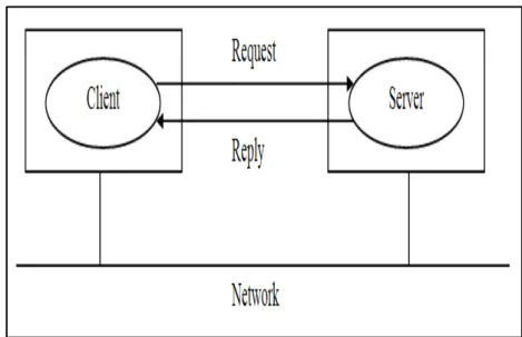
RCHITECTUREIn client/server architecture [Tanenbaum95], an application is modeled as a set of services offered by servers, a group of cooperating processes, to the clients, figure 1.1. The client/server architecture is often based on a simple connectionless request/reply
protocol. The client sends a request message to the server asking for some service. The
13
server does the work and returns the data requested or an error code. The two-tier
client-server architecture is the simplest client/client-server architecture. They are in two forms: Thin/Slim Client Model and Fat/Thick Client model.
Figure 1.1, Client/Server Architecture
The discovery solution in the client/server architecture is simple. The server has a port and network address known by the client. The clients connect to the server on its listen port. Once the connection is established, the client and server can communicate with each other. The network protocols, for example IP, do the work of sending the packet from the client to the server and back. The system calls can be invoked through the library procedures: send and receive.
Client/server architecture has some advantages:
The client/server architecture allows the division of applications into a client part and a server part.
In the client/server architecture, the resources are used effectively when a huge number of clients are accessing a high-performance server.
Another advantage of the client/server architecture is the possibility for concurrency. However, the client/server architecture has a disadvantage that it does not exploit the computing power of the client efficiently as it does with the server.
14
2.2.2 P
EER-T
O-P
EERA
RCHITECTUREPeer-to-peer P2P [Subramanian05] [Verma04] architecture is decentralized
systems where computations can be performed by any host on the network. The term
peer-to-peer refers to the concept that there are no distinctions between clients and
servers in a network of peers using appropriate information and communication systems. In P2P applications, systems are designed to benefit from the computational power available through a huge network of computers. In difference with the client/server architecture, P2P networks gives scalability, lower cost, self-organized and decentralized coordination of limited resources. Middleware may be implemented with a peer-to-peer or a client/server approach.
The P2P architecture has the following characteristics:
1- Decentralization: No central coordinating authority is necessary to coordinate the hosts in network, the use of resources or the communication between the peers in the network (communications between peers are direct).
2- Distributed resources and services sharing: Each host can have/offer both client and server functionality; providing and consuming services or resources.
3- Autonomy: Each host can alone decide when and to what degree its resources are available to other hosts.
Figure 1.2, Peer-To-Peer Architecture
15
In P2P architecture, every host could be aware of every other host, could make connection to it and could exchange data with it. However, this is impossible, so hosts are organized into “localities” with some hosts acting as bridges to other host localities, figure 1.2. One solution is the use of semi-decentralized architecture where a server is used to help establishing connection between peers in the network or to coordinate the results of a computation. For example, the network hosts can communicate with the server to observe the other available hosts. Once they are discovered, direct connection can be established and the connection to the server is unnecessary.
2.3 I
MPLEMENTINGD
ISTRIBUTEDS
ERVICES ANDA
PPLICATIONSTo implement a service or application, different methods can be used
2.3.1 R
EMOTEP
ROCEDUREC
ALLRPC
Remote Procedure Call RPC [Srinivasan95a] was invented in the early 1980s by
Sun Microsystems as part of their Open Network Computing ONC platform. It was included in Sun OS. Sun submitted RPCs as a standard to the X/Open consortium and it was adopted as part of the Distributed Computing Environment DCE. Remote procedure call systems are the origin of object-oriented middleware.
Figure 1.3, RPC Based System
16
Figure 1.3 shows the role of client and server in RPC. The client and server stub procedures are generated by an interface compiler from the interface definition of the service. The idea in RPC is to hide the message passing, and make the communications look like an ordinary procedure call. RPCs are operations that can be invoked remotely across different hardware and operating system platforms. In some systems, distributed object requests are implemented by RPCs. The server components that execute RPCs are called RPC programs. Servers may be clients of other servers to allow chain of RPCs.
2.3.2 R
EMOTEM
ETHODI
NVOCATIONRMI
Java [Sun09a] is an object-oriented programming language developed by Sun
Microsystems. Remote Method Invocation RMI [Sun09b], or Java Application
Programming Interface “Java API”, was introduced in the version 1.1 of the Java Development Kit JDK. Java RMI was considered essentially as an object-oriented Java RPC. It extends the Java object model to provide support for distributed objects in the
Java language.
Java RMI allows the invocation of methods of Java objects located in a Java
Virtual Machine “Java VM” (a self-contained Java operating environment that simulates
a separate computer) by a remote Java VM by using the same syntax as for the local invocation. The semantics of parameters in Java RMI are not the same as the distributed object model integrated into Java because the invoker (an object making a remote invocation) and the target (the implementer of a remote object) are remote from one another.
import java.rmi.*; import java.util.Vector;
public interface Profile extends Remote {
int getVersion() throws RemoteException;
GraphicalObject getAllState() throws RemoteException; }
Figure 1.4, Interface in Java RMI
17
Remote interfaces in Java RMI are defined by extending an interface provided in the java.rmi package called Remote. Figure 1.4 shows an example of a remote interface. The GraphicalObject is a class that holds the state of a graphical object. Sun is providing higher-level services on top of RMI. An example of these services are the Enterprise
JavaBeans [Matena03] which aim to provide component-based development support for
server components and adding higher-level services, such as persistence, security and transactions.
2.3.3 D
ISTRIBUTEDC
OMPONENTO
BJECTM
ODELDCOM
Component Object Model COM [Rofail99] [Eddon99] is the Microsoft standard
for creating software components. Microsoft has presented the first version of COM in 1993. COM supports the reusability since it allows building applications and systems from binary components supplied by different software suppliers. COM is a specification for the construction of binary-compatible software components; it adopts the structure of C++ virtual function tables “vtables”. This means that COM is not a library of code, a programming language, or a compiler.
COM is designed to allow the interaction of heterogeneous objects in terms of programming languages. These needs have been solved by the Object Linking and
Embedding OLE technology based on dynamic libraries DLL. In the second version of
OLE, a generic object model has been introduced for applications that run on the same workstation. In the structure of the second version of OLE model, nothing prevents that the applications can be distributed. Thus, the implementation of the new middleware named Microsoft Distributed COM “DCOM” [Microsoft96] is appeared. DCOM provides a distributed framework based on object-oriented model. Dynamic Data
Exchange DDE was the first Microsoft object technology in the middle of 1980s, then it
has changed to OLE and finally to DCOM.
The DCOM/COM technology support three methods of servers’ implementation:
DLL, local shared objects by locally running applications and remote objects. The
DCOM/COM model defines a pattern of access based on interfaces, common to all three
18
types of servers. In this context, COM is the implementation that supports local communications, and DCOM offers support for access to remote servers.
Figure 1.5, Client/Server in Microsoft® DCOM/COM
Client/Server dialogue in DCOM/COM technology can be in three ways, figure 1.5: 1- If the client and server belong to the same addressing space, COM loads the server
code and gives the client a pointer offering direct access to the server.
2- If the server does not belong to same client addressing space, but locally on the workstation, the dialogue is done through local method calls LRPC (Lightweight Remote Procedure Call).
3- Finally, if the server belongs to a remote address space, DCOM uses object-oriented RPC (ORPC).
2.3.4 C
OMMONO
BJECTR
EQUESTB
ROKERA
RCHITECTURECORBA
Common Object Request Broker Architecture CORBA is specified by the Object Management Group OMG [OMG09a]. CORBA is based on the concept of the Object Request Broker ORB. The OMG is a consortium primarily composed of the research and
software industry. It was created in 1989 to support the adoption of standards for the development of distributed object applications.
19
The first specification published by the OMG was the Object Management
Architecture OMA [OMA09]. The OMA defines the object model used in all the OMG
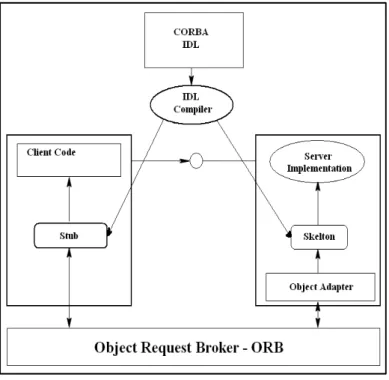
technologies that offers the objects interoperability through heterogeneous environments. CORBA is the second stage of the OMG specifications. In version 1.1, 1991, CORBA has defined the interface definition language IDL, (figure 1.6). In version 2 of CORBA, 1996, the OMG made the interoperability its priority by defining the Internet Inter-ORB Protocol IIOP. In addition to the interoperability, many services were added.
Figure 1.6, IDL CORBA
CORBA [Tari01] architecture is independent from the programming language used, the machine type and the operating system. CORBA is composed mainly of the ORB which is the heart of the CORBA architecture and the objects supported by the ORB. ORB assures the transport of requests on the network. It is responsible for intercepting methods invocations, locating the objects, carrying the invocations parameters through the network and transmitting any return values of the methods. CORBA specification has rise in several variants, such as a specification for the Wireless CORBA and a specification for the real-time called RT-CORBA. The CORBA
Component Model CCM is the main novelty of the version 3 of CORBA.
20
2.3.5 W
EBS
ERVICESThe development of World Wide Web [W3C09] [Lerner02] has allowed client computers to access to remote servers outside their own organization. Web Services [Erl05] are basically any software infrastructure that provides a service accessed remotely via the web. They are considered as a collection of operations that can be used by a client over the Internet. Each web service is identified by a Uniform Resource Identifier URI [W3C01]. Web services are client/server model. However, they are capable to play different roles according to the surrounding context, so they are not absolutely a client or
a server. Services can be distributed on the Internet. To communicate, they exchange
messages, expressed in the Extensible Markup Language XML and distributed by using Internet transport protocol such as TCP and HTTP. A service defines its needs from another service by setting out its needs in a message and sending it to that service
Data Encoding: XML Technology (XML, XDS, XST, XSLT …) Support: WS-Security, WS-Addressing, WS-Reliable …
Process: WS-BPEL, BPML
Service Definition/Finding: UDDI, WSDL Web Services Calling/Messaging: SOAP, RNIF ...
Transport: HTTP, SMTP, FTP … Figure 1.7, Web Service Standards
Although the definition of web services is large and flexible, in practice the major part of Web services is based on HTTP, SOAP, WSDL and UDDI [Newcomer03] [Cer02]. Web service protocols cover all the aspects of SOA from the service information exchange (SOAP) to programming language standards (WS-BPEL: a standard for a workflow language that is used to define process programs involving several different services). These standards are based on XML (figure 1.7), which is a human-machine notation that allows the definition of structured data, where text is tagged with a meaning identifier.
21
3. M
ODELING
M
ANUFACTURING
S
YSTEMS
3.1 M
ODELINGFMS
WITHP
ETRI NETSModeling the manufacturing systems is not new. Different modeling formalisms are used to model FMS. Petri nets and Automata theory are of the most used techniques to describe the DES. [Peterson81] has introduced Petri nets to model and analyze the manufacturing systems. Other works like [Ramadge87] has also proposed to model and analyze controllable events DES. Later, [Lin90] has introduced a decentralized control model. [Zamaï98] has presented a hierarchical and modular architecture for real-time control and monitoring of FMS. [Cho99] has proposed a centralized and decentralized control model. However, the most new modeling approaches are diverting towards the distributed modeling for the manufacturing systems [Petin05] [DaSilveira02b].
In the previous section we have introduced the different methods that are used to implement the distributed system design. In this section we will introduce the new techniques to model the manufacturing systems with Petri nets and other formalisms. We will meanly focus on the distributed approach model proposed by LAGIS/OSSc team.
3.1.1 P
ETRI NETSO
VERVIEWPetri nets have been proposed by C. A. Petri in 1962 in his PhD thesis “Communications with Automata” [Petri66]. Petri nets [Merlin76] [Murata89] are a mathematical and
graphical tool used for modeling, formal analysis, and design of different systems like computer networks, process control plants, communication protocols, production systems, asynchronous, distributed, parallel, and stochastic systems; mainly discrete event systems. As a graphical tool, Petri nets provide a powerful communication medium between the user and the designer. Instead of using ambiguous textual description, mathematical notation difficult to understand or complex requirements, Petri nets can be represented graphically. The graphical representation makes also Petri nets intuitively very appealing. They are really easy to understand and grasp. This is due to the fact that
22
Petri net diagrams resemble many of the informal drawings which designers make while they construct and analyze a system.
A Petri net graph [JWang07] contains two types of nodes: Places “p” and
Transitions “t”. Graphically, places are represented by circles, while transitions are
represented by bars or rectangles, figure 1.8. Places and transitions are directly connected by arcs from places to transitions and from transitions to places with. A place P0 is considered as an input place of a transition t if there is an arc from P0 to t. A place P1 is considered an output place of a transition t if there is an arc from t to P1. By default the weight of an arc is 1. However, an arc may be annotated with a positive number k called weight (or multiplicity). This value can be seen as k-parallel arcs. Places can contain tokens represented by dots. These tokens are the marking of places. The initial marking of places is represented in the initial marking vector m0. The graphical presentation of Petri
nets shows the static properties of the systems, but they also have a dynamic properties resulting from the marking of a Petri net.
Figure 1.8, A simple Petri Net
As a mathematical tool, a Petri net model can be described by a set of linear algebraic equations, linear matrix algebra, or other mathematical models reflecting the behaviour of the system. This allows performing a formal analysis of the model and a formal check of the properties related to the behaviour of the system: deadlock, concurrent operations, repetitive activities…
3.1.2 W
HYP
ETRI NETS?
A Discrete Event System DES [Cassandras08] [Ramadge89] is a discrete-state,
event-driven, dynamic system. The state evolution of DES depends completely on the
23
occurrence of asynchronous discrete events over time. Figure 1.9 shows the states jumps in a DES from one discrete value to another whenever an event occurs during the time.
Nearly all the DESs are complex and require a high degree of correctness. Information systems, networking protocols, banking systems, and manufacturing and production systems are falling into this classification.
Figure 1.9, Discrete Event System
One way of dealing with these problems is to model discrete event systems with Petri nets since:
1- Due to their flexibility and the formalism power, Petri nets can express concurrency, asynchronous and parallel actions, nondeterministic choice, synchronization, distribution, causality and most system properties. All these features raise the modeling power to various types of system behaviour at different abstraction levels and provide an excellent formal framework for modeling a variety of systems.
2‐ The simple graphical presentation of Petri nets model: the ease to visualize the state-flow of a system and to see dependencies between the parts of a system. This simplifies modeling and understanding systems because of its declarative, logic-based modeling principles.
24
3- The mathematical basis: Most of the computer systems developments are determined by formal mathematical methods. The main element is linear algebra; therefore many properties like net analysis and verification are possible by theoretical means.
4- Petri nets are supported by a variety of extensions and tools. These tools support the simulation of the model. The resulting provides an abstract view of systems behaviour.
5- The Petri net model permits the simultaneous occurrence of multiple events, without increasing the model complexity.
6- Many other methods and formalisms can often be transformed into Petri nets supporting them with a formal semantics.
3.2 T
HEA
RIZONAS
TATEU
NIVERSITY/I
NTELA
PPROACHThe work of at the Arizona state university/Intel [Sarjoughian05] proposes a simulation modeling combined with decision control for semiconductor supply-chain manufacturing. The importance of this proposition is the benefits for the analysis, design, and operation of supply-chain network systems. The work proposes a discrete-event system specification with four types of modules: inventory, factory, shipping link, and
customer modules with a common interface specification for control/decision commands,
figure 1.10.
Figure 1.10, Structural Composition of Inventory and Factory Models
25
The control model is generally used for the control of highly stochastic processes where selection of control actions is desired. In this model, the current and historical measurements of a process are used to predict its behaviour for future time instances. Figure 1.11 shows a model predictive control. The simulated system sends its current outputs to a system prediction model. The system prediction model then computes future outputs (i.e., controlled outputs) for some number of time steps.
Figure 1.11, The Model Predictive Control
To compose models regard the less distinct syntax and semantics for each module, figure 1.12, a knowledge interchange broker is used. This structural specification provides well-defined structural information translation from the manufacturing process network model to the model predictive control and vice versa.
26
Figure 1.12, Composition of Manufacturing Process Network and MPC via KIB This approach supports systematic specification of interactions between process dynamics and control decisions. The model composition is used to embedding model interactions inside the process and control models as is required when using interoperability in combination with model exchange.
3.3 T
HENHIT
(T
AIWAN)
A
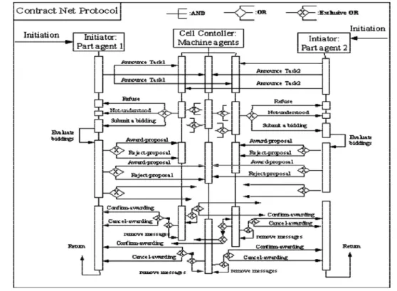
PPROACHThe National Huwei Institute of Technology [Tsai05] has proposed web-based model (figure 1.13) for distributed manufacturing control systems with problems such as process routing, allocating resources and scheduling work-pieces. The manufacturing parts and resources were presented by agent-based approaches. The supervision of the system is done by a web-based cell controller. This work presents the new evaluation of modeling with web-based technology. This new technology can support collaboration between geographically distributed work centres and makes the implementation easier.
Agents are composed of sub modules responsible for negotiation between agents, executing the different operations of the agents and recognising and analysing errors. Agents represent the machines and resources in the system. Agents communicate together through a local network or Internet. Coordination and negotiation protocols CNP were
27
used for the decision-making of resource allocation and message exchanging, based on TCP/IP protocol. Figure 1.14 shows the description of the contract net protocol using unified model language agent.
Figure 1.13, The architecture of a web-based distributed manufacturing control system
Figure 1.14, the CNP described by a unified model language agent
This work shows a new architecture for a web-based distributed manufacturing control system for the design of co-operative mechanisms for better system performance.
28
3.4 T
HECRAN
A
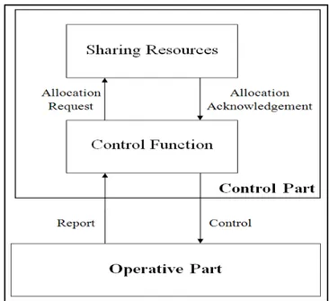
PPROACHThe recent work of CRAN [Gouyon04] has proposed a product-driven control, hierarchical architecture. This work is based on the “agile manufacturing”. The modeling technique is based on two models of the systems: a control model for the operative part elements (OPE) and a behavioral specifications model of the control part (OPE). The control model is decomposed in two points of view: production resources and products, figure 1.15.
The production control of the product is composed of (i) a routing control sub-process to the different resources and (ii) an operation sub-sub-process of the performing resource coordinated by the product. While the resource control is composed of: (i) a control sub-process that receives and deals with the messages send by the product and sends to product its actual status after transformation and (ii) an operating sub-process that transforms the sent messages of the control sub-process to physical action over the product. The products, according to their needs, will ask for resources operations.
Figure 1.15, Product-Resource Model [Gouyon04]
The modeling is realized with finite-state automata to allow modeling a process resource controlled by the product. It models the behaviour of the resource seen by the product through exchanged messages between them (request/report).
29
This work puts the product at the center of the process automation. It ensures the interoperability between the control of the resources of the manufacturing system and the product control through its routing on the system.
3.5 T
HELAG/G-SCOP
A
PPROACHThe work of LAG/G-SCOP [Henry05] [Mendez02] [Zamaï06] proposes a control, supervision, and monitoring module. [Henry05] has proposed a coordination model for the functional chain. The model is composed of two levels: coordination level to manage and coordinate the local control/communication and functional chain level that groups all the elements of the operative part, figure 1.16.
Figure 1.16, The LAG/G-SCOP Approach [Henry05]
A decision module is applied on the approach CERBERE of [Mendez02]. This module is charged to take all the required decisions to generate or select a control module, a resumption module or an urgency module (figure 1.17), depending on criteria (quality and production) and constraints (security in the operative part). To execute the requested services from the different functional chains, control rules are used. The control model has a set of the orders (request a service, report the end of a service, information sent from the environment) that it executes to impose some evolutions over the operative part and the products. These evolutions, that answer a request, must satisfy a set of security constraints.
30
Figure 1.17, Decision analysis [Henry05]
A research technique is also used in the control model that aims to find the shortest path to make a product (initial state to final state) [Zamaï06]. This technique is achieved by transforming the proposed model into a states representation containing the set of executable operations and the legal parallelism between these operations and the one in progress. This representation is modeled in automata and Petri nets.
This works have two objectives, the first one is to propose a modeling formalism for the control part and the second is the elaboration of a technique for the control synthesis.
3.6 T
HELAAS
A
PPROAHThe objective of the work developed by LAAS is to propose a generic, “heterarchical”
and distributed architecture model for the manufacturing systems [DaSilveira02a]
[DaSilveira02b]. The proposed “heterarchical” architecture is based on no client/server
architecture for the communication between entities, no external higher levels of control
to coordinate processes and the addition or modification of existent entities without significant structural changes. The work proposes an acquisition/routing block that deal with control, supervision and monitoring of the system, figure 1.18. The work proposes also a systematic procedure for distributing a centralized model of supervision and control [DaSilveira02b].
31
Figure 1.18, A generic module for control, supervision and monitoring [DaSilveira02b] To distribute a centralized model, the model is divided into “sub-models”. Each sub-model represents a resource or a set of resources and the relations with other resources. Two different models are used. The control model represents all constraints associated to the transformation of raw parts to finished products. While the process
model represents the physical and functional characteristics of the process. An entity or a module has a process sub-model and a control sub-model.
To achieve this distribution, the centralized Petri net model of two processes is transformed and split up to two Petri nets sub-models. To maintain the data coherence after distribution, a communication protocol is used. The proposed technique for the communication protocol is to centralize the decision part in one module called centralized
decider module to optimize time.
The work presented concerns the quantification of the redundancy inserted by the distribution methodology by proposing a systematic procedure, from a centralized process model (specified by Petri nets), to obtain a distributed model with partial redundancy. However, the intra-module and inter-modules communications are not detailed but assumed to be client/server protocol. Also, the work did not give a solution for the complexity associated to the process distribution as well as the coherence between entity models.
32
3.7 T
HEL
AB-STICC
A
PPROACHThe research works developed at Lab-STICC concerns the design of reconfigurable DES systems such as manufacturing systems or electronic systems. These works are structured around three main ideas [Berruet07]: reconfiguration of complex systems, a top-down methodology associated with “pivot” description languages for the co-design of systems, and a bottom-up methodology based on a component approach to allow rapid prototyping and the reuse of the code.
1- Reconfiguration of complex systems:
The reconfiguration consists on organizing the system to react in two cases: in case of a new demand of the system and in case of a reaction to a failure. To implement the reconfiguration process, they propose two key ideas. First they propose different point of views to describe a system. A system can be described according with a physical point of view or a logical point of view. For example, the logical sequence is a logical view of the architecture of a system. A second way to describe a system is the distinction between the architecture of a system and the configuration. The architecture defines the potentialities of a system. Its configuration defines a specific way to exploit the system.
The second key idea to implement this concept is to propose the introduction of a configuration task in the structure of the supervision function of the control system (figure 1.19). This introduction seems to be suitable with the context of the exploitation of the system. In this case, the decision task can select a new configuration. The role of the configuration task is to define the mode of resources that participate to the production and to define the operation that can be held by the system in this configuration.
A drawback of this proposition is to not consider the role of the maintenance function to define a configuration. For us at LAGIS, we consider that a configuration results of a negotiation between the maintenance function and the planning function because the engagement of a resource in a production depends also on the maintenance planning of this resource.
33
Figure 1.19, Proposed Control Architecture [Berruet07] 2- A top-down methodology for the design of complex systems:
One of the conclusions of the Lab-STICC is the complexity of these systems leads to decompose their control function in different tasks that are studied and implemented separately. The consequence is that they used different models of the system to be controlled without any guarantee of coherence and in consequence, without guarantee of interoperability of these tasks. To deal with this problem, the Lab-STICC proposes to use a description language to build a reference and principal model of the system. Then, all the other models required by the design methodology or the different tasks of the control can be derived from this basic models using techniques such as extraction to focus on specific aspects of the system or enrichment to take into account additional viewpoints (Figure 1.20).
34
In this context, they use techniques of model translations to automate the translation from one model to the other. In this context and also taking into account a principle like co-design that is well-known in electronics area, they propose a top down approach that allow developing incrementally the operative part and the control function of manufacturing systems. In this methodology, they propose different techniques do make static and dynamic analyses of a system. For example, using model translation technique, they can build a model that enable to evaluate the criticality of the functions of a plant. Another translations, allow to derived other models suitable with dynamical analyses by the means of simulation (joint simulation [Lallican07] and reflexive simulation [Berruet07])
Figure 1.20, Synthesis of the process of model the management proposed by the Lab-STICC [Delamotte05]
3- A bottom-up methodology based on a component approach:
In an effort to reuse and accelerating the design stage of a production system, till several years the Lab-STICC is developing a methodology for generating the control command of the transport system of reconfigurable systems. This methodology is based on the concept of component. In this approach, a component is characterized by a set of operations and a set of views. Each point of view of a component is associated with a
35
model. The main views are the operative part, the graphical view, the constraint view, the control part view, monitoring/supervision view.
It may be noted that most of these views correspond to tasks of the control command. Indeed, the idea is for each view, to get a global model from the models associated with its different components. The construction of the system model is made by a bottom up approach from basic components defined in a component library. The composition of components is done according to different levels defining other types of components: support component, effective contextual component, enriched basic
component, and system component. A component system includes all components of the
system. The nature of each component depends on the type of its operations (basic, contextual, contextual effective) [Lallican07] and its position in the hierarchy of components.
A major feature of this approach is the constraint view. It enables the designer to express constraints that must be checked during the integration of the component in a given system. The current constraints are taken into account functional and operational features, and also safety. One can think that in future they will integrate all requirements including also aspects of reliability and performance. These constraints allow linking the functional capacities of component with its state. So, they are taken into account for the generation of the model corresponding to any of previous views.
This approach has been developed and supported by software for the generation of control function of DES transport system. Compared with the top-down approach, it assumes that the designer already has the plan instrumentation diagram of the plant. Consequently, it is limited to the generation of control models for system transitique.
This approach seems to have also inspired other works such as the automation of the life environment of persons with reduced mobility [Belabbas07]. In these works, we find the concept of the component from the perspective of a black box with input and output interface that allow a rapid building of a control by aggregation of components (Figure 1.21). We will see in chapter III that the approach we propose is close to the main
36
general principle of this work. However, the Lab-STICC approach does not take into account underlying communication protocols.
Figure 1.21, PN intellectual properties proposed by the Lab-STICC [Belabas07]
3.8 T
HELAGIS/OSS
CA
PPROACHThe LAGIS laboratory develops a consistent, progressive and complete design approach of FMS. This approach is implemented by modeling controllers’ components in Petri nets formalisms and in a client/server distributed architecture [Huvenoit93] [Toguyeni06] [Bourdeaud_huy06]. The idea here is to implement each operating sequence as a PN model where each place represents the state of a product with regard to its sequence of machining operations and also its location in the plant.
The approach distinguishes two categories of controllers [Toguyeni06]: operating sequence that controls the different operations applied to a product and Graph of Coordination of Complex Resource GCCR that controls the operations applied to a
37
complex resource (a resource with several machining areas connected by transport resources). The aim of this decoupling is to reduce the complexity when designing the control of complex systems, figure 1.22:
1- Process sequences: They describe the different operations to apply to raw parts to
obtain a finished product. The Extended Operative Sequence describes the different ways to obtain a finished product from raw parts using the available machines of a plant.
2- Resource Sharing: The resource sharing implies that resources are allocated to the
requestors. Resources can be simple (mono service), or complex (multiple
services).
Figure 1.22, LAGIS Control System Architecture
To illustrate the approach, we consider the example of figure 1.23. This workshop is made of three machining machines M1, M2 and M3. The arrows in this figure represent the reachability capacity of each robot R1 to R4. R4 performs transfer operations from
FIFO IN (a buffer that permits the entry of parts in the plant) to Z1, and from Z1 to FIFO OUT. Z1 to Z4 are to transfer a part from a resource to another one. IS1 to IS6 are
intermediary stock within the conveyor. For more information, please refer to [Toguyeni06].
38
Figure 1.23, An Illustrative example of Manufacturing Plant with Flexibilities [Berruet98] To model the system, colored Petri nets are used:
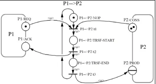
1- Extended Operating sequences: A resource operation is requested through a pair
of Request/Acknowledge places, figure 1.24. The doublet <op, id> represents the type of operation to apply to a product and the identification of each product. The request place enables an asynchronous coordination with the CPN controller of the resource.
Figure 1.24, Coordination between an operating sequence and a GCCR.
2- Resource allocation: In flexible manufacturing plant, it is necessary to solve
allocation problems. So, an allocator is needed corresponding to each resource.

![Figure 1.19, Proposed Control Architecture [Berruet07] 2- A top-down methodology for the design of complex systems:](https://thumb-eu.123doks.com/thumbv2/123doknet/2507681.51868/50.892.199.711.143.678/figure-proposed-control-architecture-berruet-methodology-complex-systems.webp)
![Figure 1.20, Synthesis of the process of model the management proposed by the Lab- Lab-STICC [Delamotte05]](https://thumb-eu.123doks.com/thumbv2/123doknet/2507681.51868/51.892.138.732.480.803/figure-synthesis-process-model-management-proposed-sticc-delamotte.webp)
![Figure 1.23, An Illustrative example of Manufacturing Plant with Flexibilities [Berruet98] To model the system, colored Petri nets are used:](https://thumb-eu.123doks.com/thumbv2/123doknet/2507681.51868/55.892.136.754.144.514/figure-illustrative-example-manufacturing-plant-flexibilities-berruet-colored.webp)