Université de Montréal
ESys.Net
A New .Net Based System-Level Design Environment
par
james Lapalme
Département d’informatique et de recherche opérationnelle Faculté des arts et des sciences
Maîtrise présentée à la Faculté des études supérieures en vue de l’obtention du grade de
Maître ès sciences (M.Sc) en Informatique
Décembre, 2003 ©James Lapalme, 2003
NJfrCY
de Montréal
Direction des bibliothèques
AVIS
L’auteur a autorisé l’Université de Montréal à reproduire et diffuser, en totalité ou en partie, par quelque moyen que ce soit et sur quelque support que ce soit, et exclusivement à des fins non lucratives d’enseignement et de
recherche, des copies de ce mémoire ou de cette thèse.
L’auteur et les coauteurs le cas échéant conservent la propriété du droit
d’auteur et des droits moraux qui protègent ce document. Ni la thèse ou le
mémoire, ni des extraits substantiels de ce document, ne doivent être imprimés ou autrement reproduits sans l’autorisation de l’auteur.
Afin de se conformer à la Loi canadienne sur la protection des
renseignements personnels, quelques formulaires secondaires, coordonnées
ou signatures intégrées au texte ont pu être enlevés de ce document. Bien
que cela ait pu affecter la pagination, il n’y a aucun contenu manquant.
NOTICE
The author cf this thesis or dissertation has granted a nonexclusive license allowing Université de Montréal to reproduce and publish the document, in part or in whole, and in any format, solely for noncommercial educational and
research purposes.
The author and co-authors if applicable retain copyright ownership and moral rights in this document. Neither the whole thesis or dissertation, nor
substantial extracts from it, may be printed or otherwise reproduced without the author’s permission.
In compliance with the Canadian Privacy Act some supporting forms, contact
information or signatures may have been removed from the document. While this may affect the document page count, it does not represent any loss of
Ce mémoire intitulé:
ESys.Net
A New .Net based System-Level Design Environment
présenté par:
James Lapalme
a été évalué par un jury composé des personnes suivantes:
Dr. Houari Sahraoui préstdent-rapporteur Dr. Jean-Pierre David directeur de recherche Dr. El Mostapha Aboulhamid codirecteur Dr. Gabriela Nicolescu membre du jury
Avec l’arrivée des systèmes embarqués qui incorporent un nombre croissant de composantes logicielles, il devient plus critique que jamais de rétrécir l’écart qui existe entre la modélisation de niveau système et l’implantation.
Dans ce travail nous illustrons, par le développement d’un nouvel environnement de modélisation et simulation basé sur le langage de programmation C#, le potentiel insoupçonné de modélisation matérielle/logicielle du .Net framework, potentiel qui a permis de pousser SystemC au-delà de ses limites.
Notre environnement, appelé ESys.Net, utilise les concepts de programmation avancés de .Net et C# tels que la réflectivité, la programmation par attribut et la création dynamique de délégués, afin de créer un environnement plus polyvalent que SystemC.
ESys.Net a pu bénéficier de plusieurs constructions puissantes du génie logiciel en raison de l’utilisation de .Net comme base. Les résultats expérimentaux que nous avons recueillis démontrent que ces constructions n’entraînent pas de pénalités d’exécution significatives.
Mots clés : modélisation, .Net, C#, simulation, système-sur-puce, langages de description, SystemC
Abstract
The need to bridge the gap between system level and implemenfation level modeling is becoming critical as embedded systems incorporate more software components. Through this work we illustrate, by developing a new modeling and simulation environment, how we can use the .Net Framework through the use of the C# programming language to model hardware/software systems and alleviate the different shortcomings of C++ that are hindering the evolution of SystemC.
Our environment, called ESys.Net, uses the advance programming features of .Net and C# such as reflection, affribute programming and dynamic delegate creation to produce a flexible solution that is meant to be an evolution of SystemC.
By using .Net as a basis for ESys.Net, we have inherited rnany powerful software engineering constmcts. The experimental results that we have gathered demonstrate that these constructs do flot ïncur a significant performance penalty.
Keywords: modelling, simulation. .Net, C#, description languages, system-on-chip, SystemC
Table of Contents
Sommaire j
Abstract ii
Table of Contents iii
Figure List vii
Table List viii
Code Exam pie List ix
Abbreviation List xi Acknowledgements xiii Preface xiv Introduction 1 1.] HDLsandSDLs I 1.2 Specfic Goals 4
1.3 OutÏine ofthis Document 5
Chapter2 StateoftheArt 6
2.] Standalone Languages 6
2.1.1 VHDL[31J 7
2.1.3 $ystemVerilog [54]. $
2.2 Programming Languuge-hased HDLs 9
2.2.1 Handel-C and OCAPI [7] 9
2.2.2 JNDL[5J[28J 9
2.2.3 SpecC [59J 10
2.2.4 $ystemC [65] 10
2.3 New Challenges in Modeling and Design 11
2.4 Recent Software Frameworks 12
Chapter 3 Advanced Programming features with C# and the .Net Framework 15
3.1 The .NETFramework 15
3.1.1 General Presentation of .NET framework [49] 16
3.2 The Cft Language 17
3.3 Advancedfrogramming Features 18
3.3.1 Introspection and Reflectivity[22J [41] 1$
3.3.2 Affribute Programming[50J [41] 21
3.3.3 Delegates 23
3.3.4 Delegates and Reflectivity 25
Chapter 4 ESys.Net 27
4.1 A Simple Example 27
4.2 Modules and Module Hierarchies 32
4.2.1 Module Declaration 33 4.2.2 Module histancing 34 4.2.3 Module Hierarchies 34 4.2.4 Module Interfaces 35 4.2.5 Modules Inner-Workings 36 4.3 Processes 38
L
4.3.1 Process Declaration and Registration .38
4.12 Static and Dynamic Process-Event Association 39
4.3.3 Process Static Sensitivity 40
4.3.4 Parallel Method Process 41
4.3.5 Process Method 42
4.4 Signais 45
4.4.1 SignaIs and Simulation 46
4.4.2 Instancing 46
4.4.3 limer and Outer Signais 47
4.4.4 A Signal’s Logical Scope 47
4.4.5 SpeciaJ Binding Cases 49
4.5 Forts and Interfaces 51
4.5.1 The Elimination of Ports 52
4.5.2 Predefined Interfaces 53
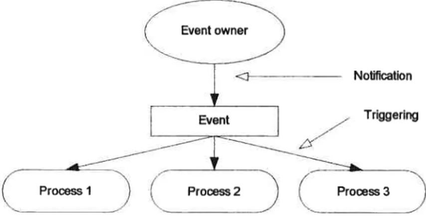
4.6 Events 55
4.6.1 Event Occurrence 55
4.6.2 Event Notification [63] 56
4.6.3 Multiple Simultaneous Event Notifications [63] [24] 57
4.6.4 Cancelling Event Notifications 58
4.6.5 Events, Signais and Clocks 58
1.7 (‘hannels 58
4.7.1 Channel Declaration and Instancing 59
4.7.2 Channels and Software Interfaces 60
4.7.3 Sensitivity 61
4.7.4 Channel hierarchies and inner-workings 61
4.7.5 Ihe IDeltaUpdatable Interface 61
4.7.6 Unification ofthe Channel Concept [63] [24] 62
4.7.7 Example [65] [24] 62
Chapter 5 Simulation Kernel 64
5.1 Modeling Directives. 65
5.2 Simulation Sernantics .66
5.2.1 SystemC [64] [63J 66
5.2.2 ESys.Net 68
Chapter 6 Comparison and Experimental Resuits 77
6.] Advantages ofthe Environment 77
6.1.1 Semantic Simplification 77
6.1.2 Programming Simplification 79
6.1.3 A Simpler Better Framework $0
6.2 Disadvantages ofthe Environment 85
6.3 Experimentat Resuits 85
6.4 Summaiy 89
Chapter 7 Summary and Future Work 92
7.1 Summaiy 93
7.2 W7iere Do You Go From Here? 94
Referen ces 95
Annex A Fifo Channel Exampie
Annex B Simple Bus Exam pie ii
Figure List
C
Figure 1: Figure 2. Figure 3.• Figure 4: Figure 5: Figure 6: Figure 7: Figure 8: Figure 9: Figure 10: Figure 1]: Figure 12: Figure 13: Simple circuit 3 MyFirstSystem 28Full Adder Module Interface Exampte 36
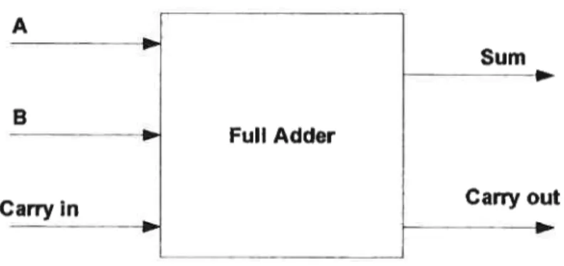
One Bit Adder Example 37
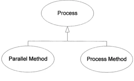
Process Sub- Types 39
Inner/Outr Signais 48
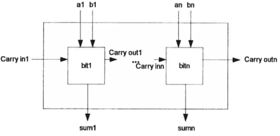
ANbitAdder 54
Event Occurrence 56
SystemC scheduter structure 68
ESys.Net Scheduler Steps 75
Leveruging ofexistingfeatures 81
General view ojihe application 87
viii
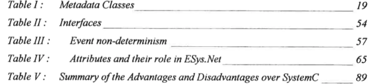
Table Lïst
Table I: Metadata Classes____________________________________________ 19
TableII: Interfaces 54
Table III: Event non-determinisrn 57
Table IV: Attributes and their role inESys.Net 65
Code Example Lïst
Code example]: Code example 2: Code example 3: Code exampte 4: Code example 5: Code exampte 6: Code example 7. Code example 8: Code example 9: Code example 10: Code example 11: Code example 12: Code exanple 13: Code example 14: (‘ode example 15: Code exainpÏe 16: Code example 17: Code example 18: Code example 19: Code example 20: Code exumple 21: Code example 22: Code exampïe 23: Code exwnpÏe 24: Type Introspection 20Value Modfication with reflection 21
Attributeprogramming exampte 22
Simple delegate exampie 24
Delegate example 24
Event keyword exampte 25
Delegates and reflection 26
ModuÏeA blueprint 29
Module3 blueprint 29
MvModule blueprint 30
MyfirstSvstem 31
MyApp 32
General module declaration 34
Module instantialion 34
Module hierarchy 35
FIFO declaration 36
Adder implementation 37
Frocess method and Paraïlet methoU dectarat ion 39
Static Sensitivity 40
$tatic Sensittvity wilh multiple eventsnaines 41
PMerhodDynamic Sensitivity 42
Process Method dynamicsensitivity 43
Triggeringon a single event 44
Triggering ajier u specfic umount oJ(ime 44
L
Code exampÏe 25: Code exampïe 26: Code example 27: Code exanpte 28: Code exampie 29: Code exampte 30: Code example 31: Code example 32: Code example 33: Code exampte34. Code exampie 35: Code example 36: Code example 37: Code exampte 38: Code example 39: Code example 40: Code exampte 41: Code exampie 42: Code exampie 43: Code example 44: Code example 45: Code example 46: Code example 47: Code example 48: Code exampÏe 49: Code exampte 50:Triggering with zero lime 44
Triggering on one event in u Ïist ofevents 44 Triggering on ail events in a list ofevems 45 Triggering on an event in u list ofevents with timeout 45 Triggering on ail Events in u list ofevents with timeout 45
Signal Instancing 47
Inner/Outer signais 49
Speciat signal binding cases 51
Boolean software interfaces 53
Event instantiation 55 Event notfications 57 ChanneÏ declaration 59 ChanneÏ instantiation 60 IDettaUpdatabte interface 6] RequestUpdate method 62
Modet Discoveiy and Registration 70
Process dicoveiy and verification 70
Aigorithm part for process methods 7]
Algorïthm partJr paraïlel methods 72
A lgorithm part for cailback hooking 73
TooÏ hooking 76
Metadata (priority) 79
Signal Discoveiy method 83
Prinling metÏ;od 84
Tool hooking 84
u
Abbreviatïon Lïst
CAD Computer Assisted Design CIL Common Intermediate Language CLI Common Language Infrastructure CLS Common Language Specification CTS Common Type System
ECMA European Computer Manufacturers Association EDA Electronic Design Automation
EDIF Electronic Design Interchange format FIFO First In, First Out
FPGA Field-Programmable Gate Arrays HDL Hardware Description Language IC Integrated Circuit
IEEE Institute ofElectrical and Electronics Engineers W Intellectual Property
ISO International Organization for Standardization JVM Java Virtual Machine
NOC Network On Chip
OOP Object-Oriented Programming OSCI Open SystemC Initiative PCB Printed Circuit Board RTL Register Transfer Level SCV SystemC Verification Library SDL System Description Language
STOC SpecC Technology Open Consortium UCI University ofCalifornia Irvin
VES Virtual Execution system
VHDL Very Hïgh Speed Integration circuit Hardware Description Language XML Extensible Markup Language
I would like to dedicate this to my mother and father
who have aiways pushed me to befter myseIl
and to Zachary and Marie-Josée, the
two
loves of my life,Acknowledgements
Above ail, I would like to thank El Mostapha Aboulhamid, the imtiator of the ESys.Net project, without whom there would be no ESys.Net. Thank you for believing in me and being very patient, your wisdom was invaluable.
I would like to thank Jean-Pierre David for lis help aid support.
I wish to express my gratitude to Luc for helping me with the design and for purting
up with my endless babbling.
Also, I would like to thank my Mom, Bmce, Irene, Dan, Marie-Josée, Steven and Gabnela for their important contributions.
I especially would like to thank Marie-Josée, my soul mate, for lier constant support
aiid patience. I would not have made it without you.
Preface
The need to bridge the gap between system level modeling and implementation modeling is becoming pressing as embedded systems incorporate more software components. Maybe a change of paradigm is needed for hardware and system modeling?
Most cunent hardware description languages have two significant advantages over generic programming language: syntactic brevity for hardware semantics and beffer constmcts for model verification. However even these advantages are melting away with the emergence of languages like Asmi. Even SystemC, a C++ based solution, has been able to incorporate fairiy simple syntactic constructs -through the use of macro- to provide hardware semantics. Assertion based venfication capabilities have usually only been supported by hardware description languages and specialized venfication languages but generic programming languages are beginning to incorporate those capabilities such as Eiffei and Asmi.
The major limiting factor of using generic programming languages for hardware modeling is that hardware semantics are flot directly present. But what if we could add the missing metadata? What couÏd we do if we had the power of certain high level programming languages: the reflective capabilities of Java, the polymorphism of Ruby, the elegance of ML, or the simple power ofPerl? Would ail ofthis change the way we think of system modeling and hardware modeling? The .Net framework currently makes interoperability between languages almost seamiess. It a]so permits the integration of custom metadata.
This thesis presents a new environment ca]ied Esys.Net that we have created for system-ievel modeling and simulation. We deveioped this solution in response to our
t
frustrations with SystemC, frustrations caused by (i) the complexities of SystemC’s underlying implementation language (C++) (ii) its overly complex Iibraiy (iii) its complex design that makes custom modifications venfy difficuit (iv) and especially
its lake of third-party tool integration capabilities. When we first started developing
E$ys.Net, our main objective was simply to port SystemC to the .Net Framework in order to eliminate certaïn of SystemC’s downfalls. However, as the project advanced, we rapïdly discovered the full potential of the .Net framework and the C# programming and decided to re-engineer SystemC in order to take full advantage of the underlying technologies. We added many new features to the overali design of the new environment in order to create a solution meant to be an evolution of SystemC.
for many years now, the ever growing gap between the available computing power offered by hardware platforms and that used by the software applications running on these platforms has been tolerated because of the need for platform independent software, independence required because of the difference in life expectancy between hardware and software products. Today, with the emergence of embedded systems, it is imperative that these new systems take full advantage of the computing power available on the underlying hardware platform and that a perfect balance may be reached between software and hardware.
A major hurdie lirniting the production of better systems, especially ernbedded ones, is the existence of an annual 30% gap between the growth of chip complexity and
human design productivity [27] . b overcorne this design crisis, it is clear that sophisticated CAD tools and new design methodologies are necessary to help designers model, simulate, partition and verify complex hardware/software systems. Over the past several years, many researchers have looked towards the creation of better design environments integrating powerful tools for system modeling, simulation, partitioning and verification [44J.
1.1
HDLs and SDLs
Before Moore’s law [481 pushed the elaboration of hardware systems by a single individual out of the reaim of reality, systems were developed in an almost artistic way by electronic engineers. When systems became overly complex, tools were created to help teams communicate vanous aspects of a hardware design [47] . The first tools available were caÏled Hardware Description Languages (HDLs) and were a spin-offofprogramming languages. A good overview of an HDL is [67]:
“In electronics, a hardware description language or HDL is a standard text-based format for describing either the behaviour or the structure, or both, of an electronic circuit. Most HDLs are restricted to describing digital circuits, but there are exceptions. HDLs have two purposes. first, they are used to write a model for the expected behaviour of a circuit before that circuit is designed and bwlt. The model is fed into a computer program, calied a simulator, that ailows the designer to verify that his solution behaves correctly. Second, they are used to write a detailed description of a circuit that is fed into another computer program called a logic compiler. The output of the compiler is used to configure a
programmable logic device that bas the desired function. Often, the HDL code that bas been simulated in the first step is re-used and compiled in the second step.”
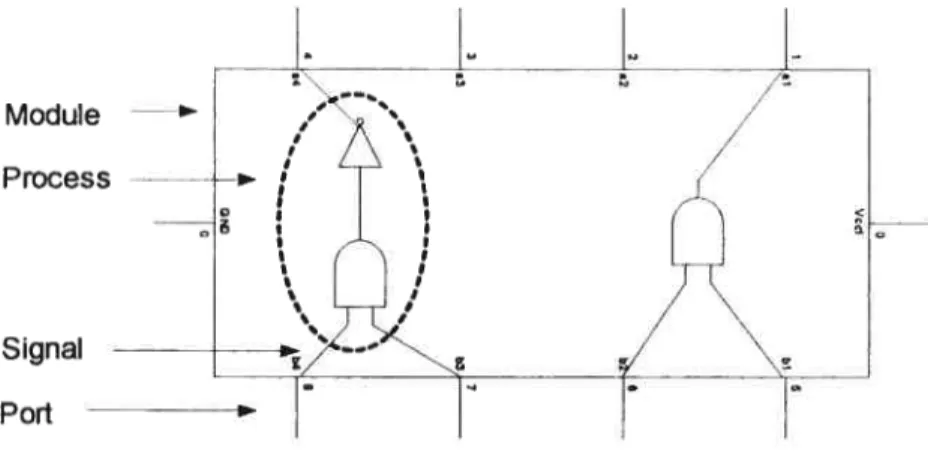
The basic difference between an NDL and a traditional imperative programming language is the presence ofa certain number ofmodeiing semantics:
• Parallel processing elements (e.g. process)
• Timing constraint elements (e.g. dock, time)
• Structural decomposition elements (e.g. modules)
• Interconnection elements (e.g. signais)
• Ports
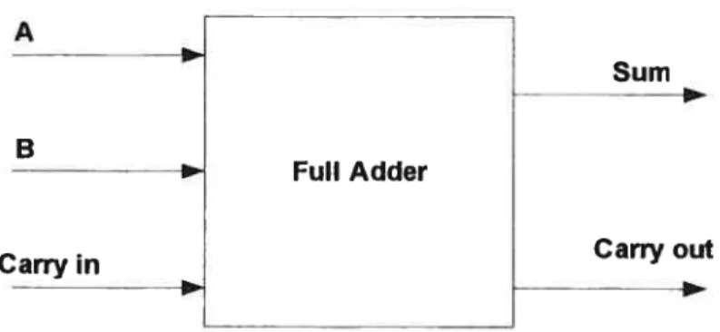
There exists no formai document that describes the modeling semantics of an HDL but cunent examples support the above modeling elements even though there syntax or name may differ. Figure I iliustrates some of the above concepts on a circuit schematic.
Module -— Ptocess
Signai
Because of the advances in electromc component intercoimections, the concept of HDLs lias been extended in recent years with the sernantics of communication channels that permit the modeling and abstraction of complex communication mediums. These new tools are called System-Level Description Languages (SDLs)
[591.
The industry and academics have for several years tned to create beffer HDLs and SDLs to aid with the neyer ending design crisis. One method that lias been expiored for the creation of these tools (FDLs and SDLs) is a library-based approach which consists of taking an existing programming language and adding to it the missing constructs and semantics for hardware and system design [7] . A second approacli is a
standalone one consisting ofthe simple creation ofa new language.
Despite ail these efforts, system designers stiii need new modeiing and simulation solutions. This is mainly due to a mandatory set of requirements for an efficient modeling and simuiation framework whïch are stili flot provided by a single existing environment:
Easier software components specification and their integration into an overalt Hardware/software system specification [66];
Clean programming features to enable iess enor-prone modeis, easier specïfication for complex systems and reuse of such specification for further designs [62];
Port
C
• Introspection features for easier debugging and analysis of complex systems
[361 [221.
• Possibility of annotating models for different purposes, e.g. directing synthesis or hooking to verification tools, creating user friendly HDL syntax [50]
• Translation to a standard intermediate format to enable the design of CAD
tools independently ofthe used description languages [401;
• Integration to distributed web-based design environment and easy system documentation to facilitate cooperation between different design groups and to allow remote processing [14];
• Multi-platform and multi-language features for describing and designing the overail embedded systems composed ofheterogeneous components [34];
• Easier memory management to accelerate the specification process and to eliminate an important source oferrors [54].
1.2
Specific Goals
The SystemC [65] modeling environment has been gaining momentum for the past several years and has become a de facto standard for systems-level modeling. However, because its underlying implementation is based on C++, ils evolution is rapidiy slowing down. We believe that SystemC will have grave difficulties in keeping tip with new environments, which wifl incorporate many advance system level modeling features for operating system and hardware/sofiware system modeling
[44] [4] [3] . The existence of an environrnent such as SystemC is very important because it is one ofthe few good modeling and simulation environments that is “free” and “open source”. Most current environments are products developed and sold by big corporation that are demanding high licensing fees.
The objective of this thesis is to propose an environment for system-level design that (1) provides most of the concepts present in high-level modeling and simulation solutions, (2) respects ail the requirements enumerated above and (3) preserves comparative performances with existing environments, by using C# and the Net Framework.
(
The mission of our environment is to use the proven environment of SystemC as a basis for a new solution that wiJl a]so be “free” and “open source”. Our enviromiient brings to the hardware/software modeling community a new solution that has ail the benefits of SystemC without having most of its drawbacks. We hope that our solution will offer designers a good alternative to expensive proprietary solutions.
1.3
Outlïne ofthis Document
Chapter 2 gives an overview of the different environments available for the modeling and simulation of hardware/software systems. It presents a brief introduction of the new challenges facing system designers today and in the future. It also presents current software ftameworks that might help in solving these new problems.
Chapter 3 presents the .Net Framework and the C# programming languages. It then goes on to expiain the advanced programming features that these two technologies support which have permitted us to create a new system-level design environment called ESys.Net.
Chapter 4 highlights the various elements that make up the ESys.Net ftarnework. They are presented individually, their semantics explained and their uses illustrated. Many code examples are given to help the reader understand the subtieties of the environment.
Chapter 5 is entirely dedicated to our simulation kemel, since the major design differences between SystemC and ESys.Net are in the simulation kernel. This chapter gives descriptions and compares the design ofboth environments.
Chapter 6 discusses the advantages and disadvantages of the ESys.Net environment; some experimental resuits are presented also.
The complexity of reality surpasses greatly our capability of synthesis and analysis. To cope with this inadequacy, we simplify things in order to create models that we can mampulate and understand. Hardware system design and the new area of hardware/software system codesign are domains that we definitely caimot cope with without simplification and abstraction. These domains are plagued by an ever growing complexity feU by technological advancements and new consumer needs. To simplify and model these complex systems, hardware description languages have been used for about 40 years now [12] [6] . They became widely used with the adoption of VHDL as an IEEE standard in 1987. There are two classes of HDLs. Standalone HDLs have their own syntax, compilers and analyzers, whereas HDLs that are in fact libraries are based on existing programming languages such as C++, C or Java. Each approach has pros and cons as we wiII illustrate in the following sections. We wilI show how recent developments in the software domain, by the introduction of new frameworks, can help in the domain of hardware/software co design. These languages permit the description of systems in a clear and standard way, permitting the easy exchange of information between people.
2.1
Standalone
Languages
This first class of HDLs is composed of languages that were developed from scratch for the sole purpose of hardware and hardware/software systems modeling. The vast majority ofthese were developed by the industry for the industry.
2.1.1
VHDL[31]
The development of VHDL was initiated in 1981 by the United States Department of Defence to address the hardware life cycle crïsis [1 6j VFJDL was meant (j) to provide a unified notation for describing electronic systems at various levels of abstraction, (ii) to be both machine and human readable, (iii) to support the communication of design data, (iv) to aid the maintenance, modification and procurement of hardware, and finally (y) to support the development, venfication,
synthesis and testing of hardware designs through a tool agnostic description. VHDL was a purely hardware description language. Early on designers noticed the absence of software and system primitives such as fIFOs, and system synchronization mechamsms such as semaphores, locks and shared variables, as well as object oriented paradigms which would help with design reuse. Also, VHDL was verbose and flot well adapted to describe components whÏch are lower than the gate level. Gate libranes were generally descnbed using in-house scripts. Test benches were also generated using special scripts even though VHDL had many useful constmcts to describe test benches. In fact, in some aspects, it is much richer than Verilog or more recent languages such as SystemC in developing gate level and register transfer level (RTL) test benches. Except for basic assertion based verification, VHDL did flot provide any other venfication capabilities. Some features were very specific to VHDL, sucli as the possibility of having metadata-like artributes. Metadata is very useful for tools that interpret a mode! either for simulation, verification, test coverage, test generation, or synthesis. It also bas the notion of the separation between the interface of a component (described by an entity) and its functionality which is described by one or more architectures. This separation is unique to VHDL; the community had to wait for recent object-oriented hardware description languages to find similar capabilities. This separation between the interface and the behaviour tvas very useful in design space exploration and to some extent in design reuse. Another unique feature of VHDL is the concept ofresolution functions which allow very weII defined protocols to modify a signal by concurrent processes; this allowed the description of very high level modeling of interaction between subsystems. In total,
flfteen different 1EEE standards around VHDL have been adopted such as VHDL
AIvIS [30] for analog design.
2.1.2
Verilog
Verilog was the main competitor of VHDL until the announcement of SystemC in
1999. Even though it appeared in 1985 it became an IEEE standard oniy in 1995[32J.
It is a less verbose language than VHDL but cornes with sorne limitations such as a narrow data type set, a resolution function restricted to “wired or” and “wired and” and no separation between interfaces and behaviour. However, it has better performances and a well defined foreign interface to hook to other languages. Currently, VHDL and Verilog are converging more and more in capability [4].
2.1.3
SystemVerilog [54J
SystemVerilog, which was adopted as a standard by Accellera in June 2002, is an extension of Verilog. It can be seen as a stack of components airned at venfication, design and system modeling. for venfication, it provides facilities both for test bench generation as well as assertions. For the design aspect, it provides many enhancements to Verilog, such as provision for communication interfaces and an enriched data type set similar to the C programming language. Since SystemVerilog
is a new product and very few case studies have been published, simulation
performance remains to be seen. Many companies donated different technologies to this environment. The white paper by S. Bailey [3] provides an excellent comparison between VHDL, Venlog and SysternVerilog. In that report we note that features available in VHDL but not in Verilog or vice-versa have been added to SystemVerilog, such as named events, partially strong typing, records and structures, hierarchy, reactive processes, interface abstraction, assertions and foreïgn interfaces, and system level primitives and mechanisms such as mailboxes, semaphores. dynamic process creation, etc. Some capabilities of VHDL have been omitted or only partially implemented such as operator overloading, general resolution functions, full-fledged attributes, configurations and binding.
2.2
Programming Language-based HDLs
The second class of HDLs is based on an existïng language such as C++, C or Java. Existing programming languages are usually missing basic hardware description semantics such as concurrent behaviour, timing elements, communications elements etc.; so this second class of BDLs is usually implemented by either providing a framework which adds the necessary missing hardware semantïcs to the base programmÏng languages or extends the languages with additional syntactic and semantic constructs — a superset approach. These are, with some exceptions, open
source environments and commercial tools that are either less evolved or targeted to a specific niche; however, they are very useful in an academic environment. In the following sections we will descnbe the characteristics of some illustrative examples.
2.2.1
Hand&-C and OCAPI [Z]
Some articles have illustrated the advantages of using HDLs based on existing programming languages
[$J.
OCAPI is based on C++ and is very efficient at system level exploration whule Handel-C is C-based and can generate efficient designs transiating them to EDIF or VHDL for implementation on FPGAs. The strength of both environments and their seamless integrations can provide a very strong design flow ftom system level to fPGA implementation.2.2.2
JHDL [5] [28]
JI-IUL is an object-onented environment; it uses exclusively object-oriented
constructs of Java for RTL hardware modeling, simulation and efficient implementation on FPGAs. The environment permits the description of synchronous digital logic circuit components and connections such as: static ce]ls, Boolean gates, registers. “parameterizable” modules etc. JHDL was developed as an exploratory attempt to identify the key features and functionalities that a good FPGA tool needs.
It has been also recently used for Intellectual Property blocks (IP) delivery through
22.3
SpecC [59]
SpecC was developed by the University of Califomia, Irvine (UCI), and first appeared in 1997. In 1999, the SpecC Technology Open Consortium (STOC) was founded. As a resuit, the SpecC language was refined and extended, leading to its second generatÏon, SpecC 2.0 which was approved by the STOC in December 2002. The SpecC language is a superset of the ANSI-C programming language. It is a formai notation intended for the specification and design of digital embedded systems. SpecC extends C with concepts essential for embedded systems design such
as: behavioural and structural hierarchy, concurrency, communication, synchronization, state transitions, exception handiing and timing. SpecC is one of the few existing environments that supporting explicit behavioural hierarchies. It focuses
on an W co-design methodology for modeling and design at the system Ievel.
SystemC channel and communication abstractions were inspired from the pioneer work done in SpecC.
2.2.4
SystemC [65J
SystemC, announced in September 1999 by OSCI (The Open SystemC Initiative), was met with much enthusiasm by both industry and academia. It was the first open source library approach environment based on C++. It is currently very popular for hardware-software system-level design. It provides ail the basic concepts used by NDLs (e.g. modules, ports, signais, timing, etc.) and more abstract concepts (interfaces, communication channels, events, etc.). However, most ofthe features for software modeling are stili missing in SystemC: dynamic process creation, process control (suspend, resume, kili, etc.), pre-emption, software specific communication primitives (monitors, semaphore, etc.). Many companies used SystemC to model in a very efficient way the system aspects of their design. As illustrated in a survey done by Doulos [17] the use of SystemC is rnainly performance modeling, architecture exploration, and transaction levei modeling and hardware-software co-simulation. The survey also shows that (i) standard HDLs continue to be used for hardware modeling and synthesis, (ii) a minonty of users use SystemC for RTL synthesis and
which are flot currently available in SystemC 2.0. Given that $ystemC 2.0 is in fact a C++ Iibrary it Iends itself to the development of very sophisticated test benches and as shown in [13], SystemC surpasses largely specialized languages such as the E language or Vera which are meant for verification and test bench development. SystemC was a good catalyst for new contributions, i.e. transaction level modeling to deal with the increased complexity of models, software engineering methodologies for interoperability design reuse [101 , simulation of network topologies [43] , and
functional verification [23] . f inally, it is the first open source HDL for which a
language reference manual has been completed in order to submit it for an IEEE standard approval. In 2003 the OSCI announced the SystemC Verification Library (SCV) which added some verification and introspection capabilities to the existing environment [1$].
2.3
New Challenges in Modeling and Design
Needs have evolved from simply describing hardware at the RTL level to including communicating subsystems, abstracting communication and buses, and dealing with low power and interconnects.
Hardware/software systems are becoming a reality and complexitv is increasing at an exponential rate. This rapid growth has pushed many to use third-party IP. Using high quality third-party ÏPs permits the reduction of design time whule improving overali quality and facilitating the design of heterogeneous systems. However, 1P reuse also brings different challenges such as:
• finding effective ways ofdelivering IPs to customers
• Insuring a sufficient visibility of the W so that customers may validate custom models and simulate the complete system contaimng in-bouse and W components
• Providing the above features while protecting the intellectual property of the vendor.
Another important revolution in the domain of integrated circuits is the integration of non-microelectronic elernents on a chip such as micro-optical and micro-mechamcal
components. These complex and heterogeneous systems also produce different problems to solve at the modeling and simulation level. We should be able to model and simulate systems expressed using different languages, paradigms, and concems
as well as components described at different levels of abstraction and protection. If
we examine the recent modeling and design environments illustrated by SystemC and SystemVerilog, we notice that the concems are: performance of simulation, ease of programming and debugging. There are also software issues such as operating systems primitives, multithreading, provision for foreign interfaces and increased levels of abstraction, as well as verification needs for the integration of components and the interaction between them. Other concems which are increasing in importance are power dissipation and the problems related to the shrinking technology going into the nanoteclmology.
Through the long history of NDLs we notice the influence of parallel and simulation languages developed in the software domain on the development of HDLs. Verilog was a sirnile combination of an earlier HDL and Occam parallel-processing language. VHDL was also largely influenced by ADA and Venlog by C syntax. We think we should go a step further to where the hardware modeling will become only one aspect within a general software ftamework enviromnent. The large success of existing HDLs was the possibility to go ftom an RTL description to a gate level implementation in a very efficient way. Up until now there have been no convincing success stories accomplished at higher levels of abstraction. Behavioural synthesis is
stiil flot adopted by the industry, and commercial tools at that level of abstraction
have flot been very successful. One success story may be the current transaction level modehng enabled by the introduction of SystemC. The focus seems to be on the combination of modeling and verification on one hand, and development reuse, delivery and integrations ofthird party fPs.
2.4
Recent Software Frameworks
Even the most recent modeling and design environments such as SystemC and SystemVerilog have many shortcomings. These are monolingual environments with limited capabilities of accessing mode]s written in other languages. The error prone
programming and the Jack of type-safe features in C++ hamper the development of SystemC. $ystemVerilog vi11 flot be an open source environment which will be a hurdie to i.miversities in developing and experimenting with CADEDA frameworks. The .NET framework was announced in 2000, one year afier the introduction of SystemC. In our opinion, it contains features that would have greatly influenced the language choice for implementing SystemC. Java was flot chosen due to its lack of performance compared to C++, the absence of operator overloading and genenc classes, etc. If we look at the C# programming language [19J introduced with .NET, we note that ail these shortcomings have been removed. M excellent comparison of C#, C++ and Java is given in [2J . It shows how C# takes advantage of the strengths
of Java and C++ and blends them in a very powerful and elegant language. The performance of C# is aiso conflrmed by different publications [42J . Many features planned for implementation in SystemC or SystemVerilog are already implemented in an efficient way in C#, such as automatic garbage collection, safe pointers, software multithreading, mailboxes, semaphores, monitors, etc.
In contrast to the JAVA environment and its virtual machine aimed only at JAVA, .NET is a multilingual environment [39J [261 , a necessity in the domain of
hardware/software modeling and design. It could be very beneficial to explore the capabilities of recent frameworks such as .NET ïn modeling, verifying and designing hardware/software systems. These frameworks bring many features to be adapted for hardware/software modeling and design such as: safe simulation of models, including models created by an unknown or semi-trusted third party, a consistent object onented programming envïronment whether the model is local or remote
[391
[56]increased reuse and multilingual support, and the existence of a published intermediate format that renders lower level tools independent of higher level modeling languages. As we can see, ail these features can be applied to development and delivery of lPs, the modeiing and simulation of heterogeneous systems as well as the development or ïntegration of modeling, synthesis and verification tools.
We should aiso benefit from the characteristics of recent software frameworks that are nonexistent in SystemC or SystemVerilog, such as the abihty to document a
L
model using metadata [501 , which can be accessed by reflection either to specify the
simulation verification or synthesis semantics, the use ofreflection to explore a model for verification, test coverage or refinement, and self-contained documentation using standards such as XML.
Features wïth C# and the .Net Framework
With time HDLs are beginuing to integrate many features that we have corne to expect of high level programming languages making them much more similar to software programming languages than hardware modeling languages. By using new software development tools and leveraging advanced programming features, improved libraiy-approach FDLs and SDLs can be developed. This section presents two new software development tools, the .Net Framework and the C# programming language. The advanced programming features, supported by these two technologies, which have had the greatest impact on the development of ESys.Net, are also presented.
3.1
The .NET Framework
Virtual machines, intermediate languages and language independent execution platforms are flot new. They were present with UNCOL in the 1950’s to the JVM in the I 990’s. Researchers have been fascinated with these concepts because they permit
an alternative path to native cornpilers that have several benefits [45]
• Portability: To implement n languages on m pÏatforms, only n -I- m transiators are needed instead of n * m transiators.
• Compactness: Source code is usually much more compact when translated to
an intermediate format.
• Efficiency: By delaying the commitment to a specific native platform as much
as possible, we can make optimal use of the knowledge of the underlying
• Security: High-level intermediate code is more amenabie to deployment and runtime enforcement of security and typing constraints than low level binaries
• Interoperability By shanng a common type system and high-level execution environment, interoperability between different languages becomes easier than binary interoperability. Easy interoperability is a prerequisite for multi language library design and software component reuse.
• Flexibility: Combining high-level ïntermediate code with metadata enables the construction of (type safe) meta-programming concepts such as reflection, dynamic code generation etc.
The .NET core represented by the CLI (Common Language Infrastructure) is a new virtual machine execution platform which was standardized in December 2001 by ECMA and in Apnl 2003 by ISO [201.
3.1.1
General Presentatïon of .NET Framework [49]
The .NET framework is a new platform that simplifies component-based application development for the highly dïstributed Internet environment. What sets the .NET framework apart from its rivais (such as the Java platform) is that its coTe, the CLI, was designed ftom the ground up to be a multi-language environment [26J [45] . At the center of the Common Language Infrastructure (CLI) is a unified type system, the Common Type System (CTS), and a Common Intermediate Language (CiL), which supports high-level notions (e.g. classes) and which is platform and prograrnming language independent. The CTS establishes a framework enabling cross-Ianguage integration, type safety, and high performance code execution.
The CLI bas four main components:
The Com mon Type System. The Common Type System (CTS) provides a rich type system that supports the types and operations found in many programming language farnilies. It is intended to support the complete implementation of a wide range of programming languages
Metadata. The CLI uses metadata to describe and reference the types defined by the Common Type System. Metadata is stored (“persisted”) in a way that is independent
of any particular programming language. Thus, metadata provides a common interchange mechanism for use between tools that manipulate programs (compilers, debuggers, etc.). Metadata is also used to augment the CIL representation of a source code.
The Common Language Specitïcation. The Common Language Specification (CLS) is an agreement between language designers and framework (class libraiy) designers. It specifies a subset of the CTS Type System and a set of usage
conventions. Languages provide their users the greatest ability to access ftameworks by implementing at least those parts of the CTS that are part of the CLS. Similarly, frameworks will be most widely used if their publicly exposed aspects (classes, interfaces, methods, fields, etc.) use only types that are part ofthe CLS and adhere to the CLS conventions.
The Virtua] ExecutioH System. The Virtual Execution System (VES) implements and enforces the CTS model. The VES is responsible for loading and nmning programs written in CIL. It provides the services needed to execute managed code and data, i.e. automatic memory management (Garbage Collection), thread management, metadata management etc. The VES also manages the connection at runtime of separately generated code modules through the use of metadata (late binding).
The CLI also gives the specification number of class libraries providing important functionalities such as thread interaction and reflection. It also provides XML [21] data manipulation, text management, collection functionality, web connectivity, etc. Alongside the CLI core, .NET Framework presents a set of classes that add supplementaiy features sucli as web services, native and web forms, transaction, scalability and remote services, etc.
3.2
TheC#Language
The C# language is a simple, modem, general-purpose object-oriented programming language that lias becorne an ECMÀ and ISO standard [19] . It was intended for
developing software components suitable for deployment in distributed environments. Although most C# implementation (Microsoft , Xixiam , DotGNU [46] [15J
[551 )
used the CLI standard for its library and nmtime support, other implementations of
C# need not, provided they support an alternate way of geuing at the minimum CLI
features required by this C# standard.
In order to give the optimum blend of simplicity, expressiveness, and performance,
C# supports many software engineering principles such as strong type checking, array
bounds checking, detection of aftempts to use uninitialized variables, and automatic garbage collection [2].
C# ïs intended for writing applications for both hosted and embedded systems ranging
from the very large that use sophisticated operating systems, down to the very small having dedicated functions. Although C# applications are intended to be economical with regards to memoiy and processing power requirements, the language vas flot mtended to compete directly on performance and size with C or assembly language.
3.3
Advanced Programmïng Features
Since the C# language relies on a runtime with the CLI’s features; it inherits interesting characteristics such as a unified type system, thread and synchronization support, and automatic memory management just to name a few. It is sometimes hard to separate the C# language and the CLI because they are quite symbiotic so .Net/C# or CLI/C# will sometimes be used throughout this document.
There are three advanced programming features that .Net/C# support that have considerable impact on software design: reflectivity, attribute programming and events/delegates.
3.3.1
Introspection a nd Reflectivïty[22] [41]
A program that can explicitly see, understand and modify its own structure is said to
have introspective capabilities. Reflectivit is a property that a program may possess that permits its structure to be accessible to itself The information that is accessible through introspection is called meta-information or meta-data. Meta-data permits the
creation of simple but powerful tools that help the design and development of software such as debuggers, class browsers, object inspectors and interpreters. There exist many languages such as Java and C# that are said to be reflective because they provide meta-information to programs written with them. Most reflective languages implement the reflection property by the means of a supporting run-time like the Java JVM or the .Net CLR, in this way separating the meta-information from the base program.
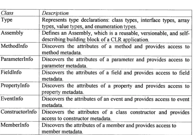
These concepts are illustrated in the reflection capabilities of the C# programming Janguage where it is possible to query the CLI to know the structure of an object. To such a queiy, the CLI retums an object that is an instance of a metaclass named Type that fully describes the type. Table I gives a list of the basic classes that make metadata accessible to a program.
Table I: Metadata Classes
Ctass Description
Type Represents type declarations: class types, interface types, array types, value types, and enumeration types.
Assembly Defines an Assembly, which is a reusable, versionable, and self describing building block ofa CLR application.
Methodlnfo Discovers the attnbutes of a rnethod and provides access to method metadata.
Parameterinfo Discovers the attributes of a parameter and provides access to parameter metadata.
fieldinfo Discovers the attributes of a field and provides access to field metadata.
Propertylnfo Discovers the attributes of a property and provides access to property metadata.
Eventlnfo Discovers the attnbutes of an event and provides access to event metadata.
Constructorinfo Discovers the attributes of a ciass constructor and provides access_to_constructor_metadata.
Memberlnfo Discovers the attnbutes ofa member and provides access to member metadata.
Code example I exemplifies the use of some basic introspection classes to query a class about its members (fields, properties, constructors, methods, etc.)
1. public class Typelntrospection{
2. public static void Maint)
3. Type theType = Type.GetType(”Assembly”);
4. Memberlnfo[1 mbrlnfoArray = theType.GetMernbers();
5. foreacli tMernberlnfo member in mbrlnfoArry)
6. Console.WriteLinef”{O} is a {1}”, member,
7. brlnfo.MemberType) ; )
Code example 1: Type Introspection Excerpt ofthe ouput:
SysiemString s localFitePrefix is a fieÏd BooÏean IsDefined(Systern. Type) is a Method
Void .ctorO 15 a Constructor
System.String CodeBase is a Property
In une 3 we get a reference to the “Assembly” type. Line 4 retrieves ail the members that are declared in the type. The rest of the code iterates through the members and prints them to the standard output.
Here is a code example that shows the true power of introspection and reflectivity.
first, we dynamically discover and change the value of a private field, and then we
dynamically discover and invoke an object’s method.
1. public class MyClass{
2. private string myString=”Old value”;
3. public int MyStringLength (String inputString)
4. return inputString.Length ;}}
5.
6. public class FieldlnfoSetValue{
7. public static void Maint)
8. MyClass myObject new MyClassU;
9. Type myType = Type.GetType(”MyClass”);
10. fieldlnfo myfieldlnfo = myType.Getfield(”myString”,
11. Bindingflaqs.NonPublic I Bindingflags.Instance);
12. Console.WriteLine(”\nfield value of ‘myString’: {O)”,
13. myFieldlnfo.GetValue( myObject H;
14. myfieldlnfo.SetValue( myObject, “New value”,
15. Bindingflags.Default, nuli , null );
16. Console.WriteLine( “field value cf ‘inystring’ : {O}”,
17. myfieldlnfo.GetValue( myûhject ) );
18. Object theObj = Activator.Createlnstance(myType);
19. Type[] paramTypes = new Type[i];
21. Methodlnfo myMethod = myType.GetNethod
22. (“MyStringLength”,paramTypes);
23. Parameterlnfo[] pi = myMethod.GetParametersO;
24. Type returnType = myMethod.ReturnType;
25. Console.WriteLinef”The parameter type: {O}”,
26. pi[OJ .ParameterType)
27. Object[j parameters = new Object[l];
28. parameters[OJ = “Hello”;
29. Object returnVal = myMethod.Invoke(theObj,parameters);
30. int val = (int)returnVal;
31. Console.WriteLine(val);}}
Code example 2: Value Modification with reflection Excerpt ofthe ouput:
The pararneter type: System.Sliing The return type: System.1nt32
Fietd value of ‘rny$tring’: Old value
field value of ‘myStringt New value
Lines 10-11 show how to get a reference to the declaration ofa private field by using the field’s name. At une 13, we retrieve the value ofthe field for a particular object. Lines 14-15 demonstrate how to modify the value ofthe field for a particular object. Line 1$ uses a static method of the Acth.’ator class to create an instance of a type. Lines 23-25 demonstrate how to discover the various aspects of a dynamically discovered class method. Lines 27-28 prepare the necessary parameters to make the dynamic cail to the method and une 29 makes the cali. This code fragment demonstrates the raw reflective powers that are missing in C++.
3.3.2
Aftribute Programming[50J [41]
Both the C# and the CLI standards defined a method for adding declarative information (metadata) to runtime entities. Since the .Net framework bas at its core the CLI, it also bas metadata support. The mechamsm through which metadata may be added to a program is called attribute programming. Attnbutes can be added to ail the elernents of a program except the body of properties and methods. It is even possible to add declarative information to the assembly, which is a unit of deployment that is similar to an .exe or .dll file on the Windows platform.
As mentioned before, attributes in .Net may be used to add extra information about
elements in a program but they also provide an elegant, consistent approach to adding declarative information to runtime entities that permit a new way of designing software. The mechanism to retrieve these attributes (metadata) at runtime has also been standardized, pennïtting software components developed by different teams or even companies to interact and discover each other through metadata. Metadata may even be used to control how the program interacts with different runtime entities. It is this capability that we exploit later in this thesis.
The following is an example of a possible aftnbute that could be used to tag a ciass with hardware type infonnation. We give an example of a class tagged with some metadata and we recover the metadata using introspection.
1. [HardwareType(”CPU”) I
2. public class MyProcessor{
3. public string technology= “FPGA”;}
4.
5. public class Metadatalnspecter{
6. public static void Maint)
7. MyProcessor obj = new MyProcessor ;
8. Type hardwaretype = typeof(HardwareTypeAttribute)
9. Type type = obj.GetType;
10. Object[J attributes =
11. type.GetCustomAttributes (hardwaretype, false)
12. foreachfObject attribute in attributes){
13. HardwareTypeAttribute ht = attribute
14. as HardwareTypeAttribute;
15. Console.WriteLine(”Hardware Type:{O}”, lit.type);}})
Code exampIe 3: Attribute programming exam pie Excerpt ofthe ouput:
Hardware Type: C’PU
The important unes are 10 and Il which show how to retrieve custom metadata from
3.3.3
Delegates
Cailbacks are an important concept in the impiementation of event handiing. Here is a good informai defïnition for the concept of a callback:
A scheme used in event-driven programs where the program
registers a subroutine (a “callback handier”) to handie a certain event. The program does flot cali the handier directly but when the event occurs, the run-time system calis the handier, usualiy passing it arguments to describe the event.
[29]
Most modem programming languages have constructs that permit the implementation of callbacks such as function pointers in C++ and interfaces in Java [2] . The .Net
framework and C# use delegates to address event handiing. The concept of delegates improves upon function pointers by being object-oriented and type-safe and improves upon interfaces by allowing the invocation of a method without the need for inner class adapters. Also, delegates are inherently multicasting — a delegate contains a list
of bounded methods that are invoked in sequence when the delegate is invoked. Ariother interesting difference between a delegate and a function pointer is that the delegate may contain an instance method in its invocation list, not only a static method as with function pointers, because the delegate keeps the information of the object that the method should be cailed on.
There are three steps in defining and using delegates: declaration, instantiation, and invocation.
Deiegates are deciared using deiegate deciaration syntax.
1. delegate void MyDelegatef);
The example declares a delegate named MyDel egate that takes no arguments and
returns no resuit.
Deiegates are instantiated like ail other object-oriented constructs.
1. class Test{
2. static void f()
3. System.Console.WriteLine(”Test.F”);)
5. static void Maint)
6. MyDelegate d = new MyDelegatefF);
7. dO;]] 1/ delegate invocation
Code example 4: Simple delegate example
The example declares a variable of type MyDelegate and then instantiates it. The delegate is then invoked.
1. class Test{ 2. static void F() 3. System.Console.WriteLinefl’Test.F”);} 4. 5. static void Go 6. System.Console.WriteLine f”Test.G”); 7.
8. static void Main()
9. MyDelegate d = new MyDelegate(F); //static binding of F
10. U += New MyDelegate(G) //dynamic binding of G
11. df);}}// delegate invocation
Code example 5: Delegate examp]e
In the above example, when the delegate is invoked, both the f and G methods are called in the sequence in which they were bound to the delegate.
C# has added a key to add event handiing semantics to a class field that is a delegate type: event. A delegate qualified with the event keyword bas no effect on the field from inside the class or class instance’s scope. from outside the scope, however, the field may flot be invoked, the field can only be used on the lefi-hand side of the +=
and —= operators. The += operator adds a handier for the event, and the -= operator
rernoves a handier for the event.
1. public delegate void DataNotifyHandler(object sender,
2. System.EventArgs e);
3.
4. public class DataProducer{
5. public event DataNotifyHandier notify;}
6.
7. public class DataConsumert
8.
9. void DataReady(object sender, EventArgs e)
10. Console.WriteLine(”Data is ready!”);}]
12. public class App{
13.
14. static public void Main()
15. DataProducer prod = new DataProducerU;
16. DataConsumer com = new DataComsumerU;
17. prod.notify+= new DataNofityHandler(com.DataReady);
18.
Code example 6: Event keyword exampte
The above example shows a DataConsumet class that adds DataReady as an event handler for the notify event of a DataProducer class which is declared with the event keyword. This example shows how a simple and naive way of synchronizing a producer and consumer.
3.3.4
Delegates and Reflectivity
A powerfuli combination is the use of reflection in collaboration with delegates. Compared to most language .NetJC# permits methods to be bound to a delegate at runtime. For example, in C++, the name of the method that is bound to a function pointer must be known at compile time, but in .Net/C# it is possible to create a delegate type object with a static method of the Delegate class. The method takes as parameters an object and the name of the method which should be bound to the created delegate.
With reflectivity, it is possible at runtime to discover the names of the various methods that an object supports, so it is possible to dynamically discover an object’s method and bind it to a delegate.
The example below illustrates this flexibilïty:
1. public delegate void myMethodDelegateO;
2. public class MyCiass{
3. static public void Hello{
4. Console.WriteLine(”Hello”) ;}
5. public void GoodNorningf)
6. Console.WriteLine f”Good Morning”);
7. public void ByeC){
8. Console.WriteLine (“Bye”);))
C
11. static event myMethodDelegate myDelegate;
12. static public void Maint)
13. MyClass obj = new MyClass();
14. Type obj Type = obj .GetTypeO;
15. Type myMethodDelegateType = typeof(myMethodDelegate);
16. foreaclifMetliodlnfo method in
17. objType.GetMethods (Bindingflags.DeclaredOnly
18. BindingFlags.Static
19. BindingFlags.Instance I
20. BindingFlags.Public))
21. if(metliod.GetParameters() .Length == O &
22. method.ReturnType == typeoffvoid))
23. if(method.Isstatic)
24. myDelegate+= (myMethodDelegate) Delegate.CreateDelegate
25. (myMethodDelegateType,method);
26. else
27. myDelegate+= (myMethodDelegate) Delegate.CreateDelegate
28. (myMethodDelegateType,obj,method.Name);
29.
30. if (myDelegate f null)
31. myDelegateO;}}
Code example 7: Delegates and rellection
Ibis example iterates through ail the static and instance methods that are declared public of an object (obj) of type MyCtass. Each method is verified for two conditions: no formai arguments and a void retum type. If the method fulfits the two conditions it
is then bound to a delegate object (myDelegate). Static and instance methods of an
object are bound dynamically to a delegate in different ways. Line 23-25 show how to bind a static metliod. Lines 26-28 show how to bïnd an instance method. Line 30-31 test the delegates in order to discover if it has been initialized. If it bas a value other than nuiT it is invoked.
The core of our environment makes use of an algorithm similar to code example 7, however, we incorporate the use of attributes to selectively filter the methods. Dynamic method discovery ami delegate creation are useful because they enable a simp]e and elegant solution for implementing entry points in a simulation kemel for third-party tools. We also use them to dynamically create the processes of our simulation model (see Chap 5).
After struggiing with the downfalls of SystemC, we looked for another alternative that would enable us to model systems in a simple effective manner ami that would allow us to explore different types of CAD and EDA tools for partition, venfication and synthesis. Afier looking at many environments and languages we stumbled cross the C# language and the .Net Framework. We immediately noticed that C# and .Net brought together several important features from vanous existing solutions i.e. Java, C++, ML, etc. and brought several new features that would probably enable the developrnent of a new environment for system-level design based on the previous work of SystemC.
This section describes the fruit of our labor: Embedded Systems with .NET, a new system-level design environment based on SystemC. E$ys.Net is meant to be an evolution of SystemC by offering the same modeling capabilities but in a more elegant package. ESys.Net also imiovates on SystemC by using a better underlying programming language which permits it to inherit operating system primitives, a rich sofiware component libraiy for rapid tool development and powerful runtirne.
The next section wiIl present briefly with the aid of an example the core elernents of E$ys.Net. These elements will then be explained in depth in subsequent sections.
4.1
A Simple Example
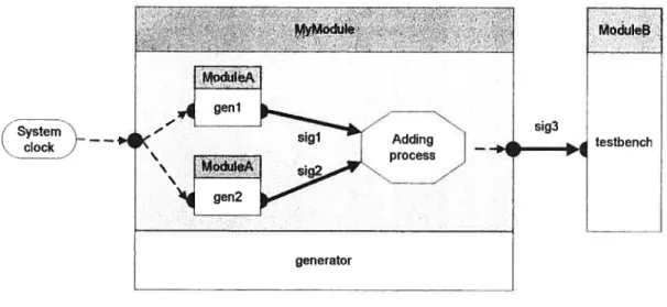
The best way to present a new tool is with an example, here is a simple example called “MyFirstSystem” that we will use to present our environment.
28 MyMo.ftite ModuleS ModuleA geni ——, — sigi z — — sig3 testbench ModuleA genetator
Figure 2: My First System
“MyfirstSystem” is a model for a simple synchronous hardware component that is being tested with a testbench. The hardware component, named “generator”, generates an integer on its output port on each positive edge ofthe main system dock. When a new value is generated by the hardware component, the testbench is notified of the new value by the “generator”. The testbench then reads the new value from its input port and then prints it out.
Like most real hardware components, the “generator” is composed of sub components. These sub-components are responsible for generating an integer value
on each positive edge of the main system dock which is then added together by a
computation process in the encapsulating component.
The following code represents the bluepnnt for the two sub-components (geni and gen2):
1. public class ModuleA BaseModule{ 2. public dock clk;
3. public outlnt porta; 4.
5. public ModuleAO: baseO{} 6.
7. [Process]
8. [EventList (“posedge”, “clk”) I
9. public void Gen()
11. for(int i=O;O<100;i++) {
12. porta.Value=i;
13. Waitf);}}}}
Code example 8: ModuleA blueprint
Code example 8 declares the specification for a component that has one input port, cikand one output port, porta. The input is used to drive the component with a dock signal. The output is used to transmit an integer value that is generated by the Gen method. Hardware elements are concurrent by nature, they ail compute in parallel. To indicate that the Gen method represents a computation that is concurrent, which we cali a process, we tagged the method with a Process aftribute. Ail methods tagged with the Process aftnbute execute concurrently. The EventList attribute indicates that the Gen method is sensitive to the positive edge (posedge) ofthe clk input
The role of the EventList tag is to indicate an association between a process and a triggering object which is implemented with the Event class that is defined in our environment. As its name implies, the Event class represents an event that may occur during the simulation ofthe model. When an event is triggered, the processes that are associated to an event are executed. In the above example, the clk field owns an event called posedge — that represents the event of a positive edge-, when the dock
represented by clk field generates a positive edge, it triggers it posedge event.
The Wait method eau in the Geit method indicates that the execution should stop at that point and then resume when an event on its triggers list occurs.
1. public class NoduleB BaseModule 2.
3. public inlnt porta;
4. public Event synevent;
5.
6. public MoUulBC) basef) {}
7.
8. [Process]
9. public void Runf)
10. while(true){
11. Wait (syn event)
12. Console.WriteLine (porta.Value); ] I
This code fragment represents the bluepnnt of the testbench module. It only has an input port porta. its Run method lias been tagged with a Process attribute so it will run concurrently with the Gen methods of tlie geni and gen2 sub-components. What
is distinct about this module is that the method indicated to become a process does flot have an EventList attribute. This is not a problem, before the simulation starts, ail
methods that are processes that do flot have an event list are executed once. The Wait method cail with an event as an argument within the Run method indicates that the method wili stop at this point and wait until the event is triggered.
1. public class MyModule BaseNodule
2. public outlnt porta;
3. public dock clk;
4. public Event syn event = new EventO; 5.
6. ModuleA genl = new ModuleAO;
7. ModuleA gen2 = new ModuleAU;
8. IntSignal sigl = new IntSignalf); 9. IntSignal sig2 = new IntSignalO; 10.
11. public MyModule() baseO{}
12.
13. [PMethod]
14. [EventList(”sensitive”,’sigl”,”sig2”)J
15. public void Addf)
16. porta.Value = sigl.Value + sig2.Value;
17. syn event.Notify(O);}
18.
19. public override void BindingPhaseO{
20. genl.clk = clk;
21. gen2.clk = clk;}}
22.
Code example 10: MyModule b]ueprint
This code fragment is the bluepnnt for the main module called “generator”. It lias an input for a dock signal and an output for an integer value. It atso contains two sub components of type ModuleA — the blueprint presented ear]ier-, two signais used to
connect tlie sub-components together and an event instance that will be used to notify the testbench when the “generator” generates a new value. The component lias a method that is tagged with the Pliethod attribute. This indicates that the method
(
should be considered as a concurrent process like a method that is tagged with Process. The difference between a method tagged with PMethod and Process is in their simulation implementation. A method tagged with a Process attribute keeps its state between Wait method cails. A method tagged with a PMetltod tagged cannot
eau the Wait method, it is executed like a normal method cali so the state of variables
declared in the body ofthe method are flot kept between execution.
The EventList of the Add method indicates that the method is sensitive to the two internai signais (sigi and sig2) that are used to communicate with the sub components. Each signai owns an event cailed sensitive. A signal triggers its sensitive event when a new value that is different from its former value is written to the signai. The Notify method cal! in the Add method on the syn_event event causes the event to be triggered which causes the testbench module’s Run method to be awaken and executed.
The last method in the “generator” component is called BindingPhase. It is invoked before the simulation starts and is used to propagate signais throughout a module hierarchy for binding purposes. Binding is necessary to connect a signal to a port such
as the clk signal being bound to the cik ports ofthe two sub-components.
1. public sealed class MyFirstSystem:Systeinl’4odel{
2.
3. TopModule top new TopModuleO;
4. Modulefi testbench = new ModuleBf);
5. Clock clk new Clockf”clockl”,4);
6. IntSignal sig3 = new IntSignalU;
7.
8. public Myfirstsystem tlsysteiïïManager manager) base(manager) t 9. top.clk = clk;
10. top.porta = sig3;
11. testbencli.porta = sig3;
12. testbencli.synevent = top.synevent;}}
Code example 11: MyFirstSystem
The overali “MyFirstSystem” system is defined by creating a ciass that inherits from 8yternModet. This class is used to encapsulate a system and is the entry point for the simulator to extract the model to be simulated. In this ciass we instantiate the main
![Figure List C Figure 1:Figure 2.Figure 3.•Figure 4:Figure 5:Figure 6:Figure 7:Figure 8:Figure 9: Figure 10: Figure 1]:Figure 12:Figure 13: Simple circuit 3MyFirstSystem28](https://thumb-eu.123doks.com/thumbv2/123doknet/7754560.253908/11.918.182.806.302.717/figure-figure-figure-figure-figure-figure-figure-myfirstsystem.webp)