HAL Id: hal-00711316
https://hal.archives-ouvertes.fr/hal-00711316
Submitted on 23 Jun 2012
HAL is a multi-disciplinary open access archive for the deposit and dissemination of sci-entific research documents, whether they are pub-lished or not. The documents may come from teaching and research institutions in France or abroad, or from public or private research centers.
L’archive ouverte pluridisciplinaire HAL, est destinée au dépôt et à la diffusion de documents scientifiques de niveau recherche, publiés ou non, émanant des établissements d’enseignement et de recherche français ou étrangers, des laboratoires publics ou privés.
Wireless Sensor Network on Board Vessels
Hussein Kdouh, Gheorghe Zaharia, Christian Brousseau, Guy Grunfelder,
Hanna Farhat, Ghaïs El Zein
To cite this version:
Hussein Kdouh, Gheorghe Zaharia, Christian Brousseau, Guy Grunfelder, Hanna Farhat, et al.. Wire-less Sensor Network on Board Vessels. International Conference on Telecommunications, Apr 2012, Jounieh, Lebanon. pp.1-5, �10.1109/ICTEL.2012.6221242�. �hal-00711316�
Wireless Sensor Network on Board Vessels
H. Kdouh1, G. Zaharia1, C. Brousseau2, G. Grunfelder1, H. Farhat1, G. El Zein1 Institut d’Electronique et de Télécommunications de Rennes (IETR)
1
INSA de Rennes, 2Université de Rennes 1 UMR CNRS 6164, Rennes, France
Abstract—Wireless Sensor Networks (WSNs) have been used
recently in different applications such as environmental monitoring and target tracking. Few papers have investigated the viability of this technology on board ships. We study in this paper the possibility of replacing the wired shipboard monitoring system by a WSN. This environment has a specific metallic structure which makes the wireless communication more difficult than in other classical indoor and outdoor environments. Two types of experiments have been carried out on board a ferry-type boat during sailings and stopovers. The first experiment consists of point-to-point measurements using ZigBee-based equipments and the second one consists of deploying and testing a WSN on board the ferry. These tests have been conducted during realistic conditions on board the ferry, which give a high level of reliability to results with respect to the earlier experiments on board ships moored to the harbor. In spite of the harsh metallic structure and the dynamic environments on board the ferry, the obtained results have shown that the wireless solution may be a cost-effective alternative of the huge amount of cables used actually to connect sensors to central control units.
Keywords- wireless sensor networks; ships; IEEE 802.15.4; measurements
I. INTRODUCTION
Ships and boats are an important part of modern commercial and military systems in daily life and in armed conflict. Fishing boats are used by millions of fishermen throughout the world. Military forces operate vessels for combat, transport and support forces ashore. Commercial vessels, nearly 35,000 in number, carried 7.4 billion tons of cargo in 2007 [1]. Nowadays, navies and ships manufacturers aim to use automation on board ships as much as possible in order to provide safety and efficiency of operation, and in the same time to reduce the number of crew members. The actual shipboard monitoring system contains several thousands of sensors connected to a central processing unit via copper wires. Tens of kilometers of cables are installed on board a ferry-type vessel, increasing its cost, weight and architecture complexity [2]. The proposed solution is the use of wireless technologies on board ships to reduce or eliminate the huge amount of copper wires. However, wireless communications on board vessels are limited by several factors. Metallic structure of bulkheads and watertight doors severely decrease the power of received radio signals. Moreover, propagation effects, like the multipath due to the metallic environments on board ships, can be a serious cause of received signal degradation [3].
Wireless Sensor Networks (WSNs) have gained worldwide attention in recent years, particularly with the great development of Micro-Electro-Mechanical Systems (MEMS) technology and the development of small autonomous devices called sensor nodes. These nodes can sense, measure and gather information from the environment, and construct self-organizing and self-configurable networks to transmit collected data to a central base station [4]. Various WSN applications have been addressed and reported in the literature, including industrial process monitoring [5], natural-disaster forecasting [6], habitat monitoring [7], and climate and soil monitoring for use in agriculture [8]. WSNs are generally constrained by the reduced computing, radio and battery resources of sensors. Applying this technology on board ships will face more challenges with respect to other classical environments. The metallic structure and the dynamic environment (frequent movements of persons and objects) affect severely the link quality between nodes. Sensor nodes and routers must be carefully placed in order to provide best network connectivity. The problem of radio propagation and wireless network connectivity seems to be more critical than the power consumption issue, which may be solved by the power supply of the vessel for critical nodes (such as important routers or frequently-sending nodes).
Few papers have studied the wireless communication on board ships using ubiquitous technologies. In [9], authors have conducted ZigBee measurements on the passenger deck of a ship and a small wireless sensor network has been deployed between the main engine room and the control room. In [10], a WSN has also been tested successfully in the main engine room of a ship. In [11], a WSN on board a ferry moored to the harbor has been tested. All these measurements have been carried out when the ships were moored to the port. To date, experiments during ship operation have not been carried out. Since the main engine or other equipments and the passengers’ movements can affect the quality of wireless communication, it is necessary to conduct measurements with a ship in operation. In this paper, we investigate the feasibility of wireless sensor technology on board ships. Point-to-point (P2P) communication tests have been conducted and a WSN has been tested on board a ferry-type boat. These experiments have been carried out during sailings and stopovers between Roscoff (France) and Plymouth (United Kingdom). All realistic conditions (crew's and passengers' movements), fixed and mobile vehicles (“mobile” only during stopovers) in the parking, turned on motors and generators in engine rooms, etc…) as well as different communication scenarios
This work is a part of SAPHIR project supported by "Pôle Mer Bretagne" and "Région Bretagne".
(communication between rooms with opened or closed doors, communication between decks,...) have been considered. The results of the P2P communication tests have been exploited to place the sensor nodes in the three lower decks of the ferry, which constitute the most hostile environment on board. The network has been tested during 105 hours. Sensing data (temperature, humidity, pressure, ambient light and acceleration) as well as data packets (sent and dropped packets, received signal strength indicator, battery voltage) have been gathered and sent by sensor nodes to a base station placed in the control room.
The remainder of this paper is organized as follows: Section II describes the measurement setup, including the environments and the test equipments. Section III presents the P2P communication tests and the obtained results. The deployment procedure and the results of the WSN test on board the ferry are shown in section IV. Finally, conclusions are drawn is Section V.
II. MEASUREMENT SETUP
This section describes the considered environments and the technology used for the measurement campaigns. Some details are given when describing the measurement sites, as they have a great influence on the wireless propagation and the network connectivity.
A. Measurement Sites
These experiments have been carried out on board the "Armorique" ferry of the "Brittany Ferries" company. The deckhouse of the ferry is constituted of 10 decks. The measurement tests have considered a part of the three lower decks. The first deck houses the engine rooms (main and auxiliary engine rooms, pump room), the second deck contains the control room and several other rooms and the third room is the parking. These configurations have been chosen for several reasons. Firstly, the considered environments are the most hostile on board the vessel for the wireless propagation (totally metallic bulkheads and watertight doors). Secondly, most of the sensors (and the most critical ones) of the monitoring system are located in these areas. And finally, a WSN deployed in these areas can simulate of all communication scenarios on board the vessel (communication between compartments or between decks, door opened or closed,...). The engine rooms of “Armorique” ferry are constituted of several equipments such as engines, generators, valves and pumps. All equipments and walls in this environment are made of metals, mainly the steel. The parking (deck 3) is a big hall with metallic walls. A stairway, with two metallic watertight doors on its two sides, connects the control room and the parking. During 105 hours test, the ferry has made 10 cruises between Roscoff and Plymouth. After each sailing, the ferry makes a stopover for charge, discharge and maintenance. During this period, vehicles enter to or exit from the parking. Crew members were in continuous movement between rooms and decks containing sensor nodes, which leads to a frequent doors opening and closing. This frequent motion on board the ferry changes the characteristics of the propagation channel and modifies frequently the link quality between nodes.
B. Used Technology
Several wireless standards have been developed for WSN with the key design requirement for low power consumption. IEEE 802.15.4 is probably one of the most used standards in this type of application since its protocols are designed for low data rate, short distance, and low power consumption communication applications in conformity with WSN constraints. We have used equipments based on IEEE 802.15.4 and operating in the 2.4 GHz ISM frequency band for both P2P and WSN tests.
For the P2P measurements, two ZigBee protocols analyzers from Silicon Laboratories have been used, one sending 100 ten-byte packets and the other receiving these packets. The two nodes were placed at 1.80 m height. Node antennas were omnidirectional, vertically polarized and with a gain of 1 dB. The Received Signal Strength Indication (RSSI), as well as the percentage of received packets with respect to the total number of sent packets (transmission ratio), were measured in order to evaluate the transmission quality.
The shipboard WSN test was carried out using Crossbow’s MICAz wireless sensor nodes (motes). Each node has a maximum data rate of 250 kbps and is equipped by a sensor board supporting temperature, humidity, barometric pressure, ambient light and acceleration sensors. Rather than inventing a new routing protocol, we have decided to apply Crossbow’s XMesh routing protocol to evaluate its efficiency in such a hostile environment. XMesh is a link-quality based dynamic routing protocol that uses periodic Route Update messages (RU) from each node for link quality estimation. Each node listens to the radio traffic in the neighborhood and selects the parent that would be the least costly in terms of transmissions number to reach the base station [12]. XMesh may be configured in one of three power modes: High Power (HP), Low Power (LP) and Extended Low Power (ELP). As we are dealing with the problem of network connectivity, we have used the HP mode with motes always powered. This mode allows fixing a minimum value of 0.3 seconds to the period of data transmission by sensor nodes. A huge number of packets is sent by each sensor node during the network test, which simulates an emergency case where a large number of sensors send data frequently and simultaneously to the base station. Moreover, this mode gives a reliable statistical idea on the links quality and the behavior of nodes with respect to the hostile and dynamic environment.
C. Frequency Band
It is worth mentioning that decks 5 to 10 of the “Armorique” ferry are equipped by a WiFi network operating also at the 2.4 GHz ISM frequency band. In order to ensure that our measurements are not affected by the WiFi communications, we have conducted a preliminary measurement campaign with a spectrum analyzer and an omnidirectional antenna. The objective of this test is to detect the idle frequency sub-bands in the 2.4 GHz frequency band to use them in the later tests. All rooms included in the measurements sites have been scanned by this procedure.
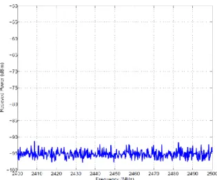
Fig.1 shows a measurement sample taken in the main engine room. All other results are similar to this sample.
Figure 1. Received power in the 2.4 GHz ISM Frequency band in the main engine room
The received power level shows that there is no WiFi transmission detected in the below-deck spaces of the ferry. The metallic structure of ceilings and floors prevents radio leakages between different decks. The results of the preliminary test indicate that the 2.4 GHz ISM frequency band is totally idle in the below-deck spaces of Armorique. Therefore, we have ensured that no interference will occur between our measurements and the WiFi communications on the upper decks.
III. POINT-TO-POINT COMMUNICATION TESTS
We present in this section the results of P2P measurements conducted in the three lower decks of the “Armorique” vessel. As previously stated, the results of these experiments will be a guide for the WSN deployment. Hence, we tried to test all communication configurations that may be faced by the sensor nodes of the WSN, including the communication between nodes placed in the same room, or between nodes placed in adjacent rooms (opened or closed door), or between nodes located in two adjacent decks.
A. Communication between Nodes placed in the Same Room
We have selected the parking to test the scenario of communication between two nodes placed in the same room. The parking is the largest room and the most dynamic area in the chosen measurements sites. The arrangement of the parking changes during sailing and stopovers. During sailings, a lot of vehicles are inside. However, during stopovers there will be a charge and discharge of vehicles and a part of the floor (represented by a rectangle, called “Acces to deck 2”, in Fig. 2) will be rotated for 90 degrees to allow the access to some chambers in deck 2. This dynamic arrangement does not exist in the other rooms where the motion is limited to the crew's movement and the doors closing and opening. The transmitter was placed at the location called “Tx” in Fig. 2 and the receiver was placed at 3 different locations (Rx1, Rx2 and Rx3 in Fig. 2). The first scenario studied is the effect of vehicles movement on the quality of the radio link between nodes. The transmission ratio at Rx1 was higher than 96 % for both cases
Figure 2. Locations of the transmitter (Tx) and the receivers (Rx1 to Rx3) in the parking of the “Armorique” vessel.
of fixed and mobile vehicles. The average of RSSI was higher when vehicles were moving (the average difference is 12 dB).
However, the standard deviation of RSSI was 8 dB when vehicles were moving and 3 dB when they were fixed. This difference is simply explained by the vehicles movement which randomly blocks or allows the direct visibility between the transmitter and the receiver. The second studied scenario is the effect of the rotation of the access to the deck 2. During stopovers, this part of the floor becomes perpendicular to the floor, which blocks the visibility between nodes placed in its two sides. To simulate this case, we have measured the transmission ratio at location Rx2. The result has shown that the transmission ratio is 100 %. The reflective walls of the parking create a guiding effect for the radio waves despite the No-Line-of-Sight (NLoS) configuration between the transmitter and the receiver. The effect of this obstacle becomes more significant when the distance between Tx and Rx becomes larger. At location Rx3 for example, the transmission ratio decreases from 20 % to 7 % when moving the access.
B. Communication between Nodes placed in Adjacent Rooms
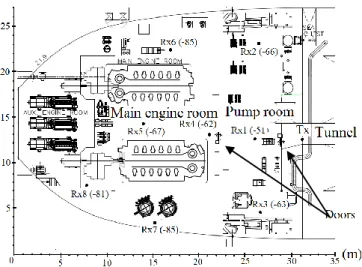
P2P measurements have been conducted in decks 1 and 2 to study the scenario of two nodes located in adjacent rooms (with metallic bulkheads) and the effect of door closure on the link quality. Fig. 3 shows the locations of the measurement points in the bottom deck of the “Armorique” vessel and the average of RSSI on each receiver location. The transmitter (Tx) was placed in the tunnel and the receiver (Rx) was placed at 8 different locations in the pump room and the main engine room. The tunnel, the pump room and the main engine room are separated by two watertight doors. Some crew members were moving between these two rooms. The standard deviations of RSSI values were ranged between 0.82 and 3.12 dB. The results of this test show a transmission ratio between 98 % and 100 % for the Rx1, Rx2, Rx3, Rx4 and Rx5 locations when the two watertight doors are opened. This ratio decreased to 73 % for the other locations in the main engine room. Closing the watertight door separating the tunnel and the pump room did not affect the transmission ratio for the Rx1, Rx2, Rx3 and Rx4 locations, but the RSSI decreased of about 17 dB. However, the transmission ratio for the other locations in the main engine room became null. After closing the second watertight door (between the main engine room and the pump
Figure 3. Locations of the transmitter (Tx) and the receivers (Rx1 to Rx8) in the bottom deck of the “Armorique” vessel.
room), the transmission ratio became null for every location in the main engine room.
Additional tests on the second deck which has a similar architecture (watertight doors, metallic bulkheads, size, etc…), have shown similar results. Communication is possible on these decks between two adjacent compartments even if the watertight door was closed. However, closing the door induces an additional attenuation of 17 dB to 25 dB. Moreover, when the two watertight doors are closed between the transmitter and the receiver, the communication becomes impossible. These results show that doors allow the radio leakages between adjacent rooms.
C. Communication between Nodes placed in Adjacent Decks
A critical challenge that can be faced between two nodes in a shipboard WSN is the connectivity between different decks. The metallic structure of floors and ceilings makes difficult the connectivity of the different levels of the WSN. We have simulated this scenario by placing the transmitter in the control room (deck 2) and the receiver in the parking (deck 3). As previously stated, deck 2 and deck 3 are connected by a stairway which has a watertight door on each side. These two doors have been maintained closed during experiments (which is the default case during sailings). The measurement results have shown that no packets have been received successfully, even when we opened one door. However, placing the receiver or the transmitter inside the stairway increases the transmission ratio. Therefore, the direct communication between deck 2 and deck 3 is not possible. Nevertheless, placing a relay node in the stairway may be a good solution to ensure the connectivity of the nodes placed in the parking.
IV. WIRELESS SENSOR NETWORK DEPLOYMENT
This section describes the deployment of the WSN on board the “Armorique” vessel and presents the obtained results.
A. Deployment Procedure
The objective of P2P communication tests was to draw engineering rules concerning the nodes placement. We have
concluded from these experiments that the metallic structure of floor, ceiling and walls has a constructive effect on wireless communication between two nodes placed in the same room and a destructive effect when nodes are placed in different rooms or different decks. However, doors and stairways are the main and probably the only ways for radio leakages between adjacent rooms and adjacent decks respectively. From these conclusions, sensor nodes of our WSN on board the “Armorique” ferry have been placed in front of doors and in stairways to ensure the connectivity of the network.
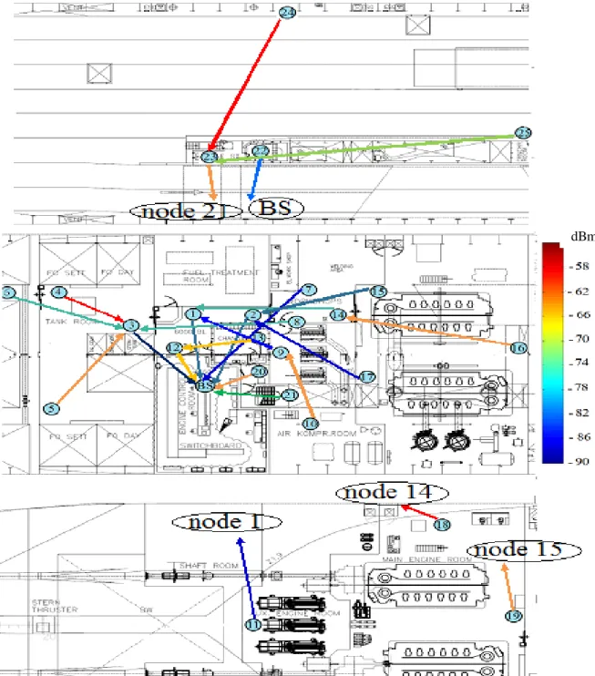
The deployed WSN is constituted of 25 sensor nodes placed in decks 1, 2 and 3. Fig. 4 shows the nodes locations on the maps of Armorique. Nodes 1, 2, 3, 4, 6, 7, 8, 9, 10, 12, 14, 15 and 23 have been located in front of doors. Nodes 20, 21 and 22 have been placed in the stairway between the control room and the parking. Nodes 5, 11, 13, 16, 17, 18, 19, 24 and 25 were located in positions containing real sensors in the tank room, the changing room, the auxiliary engine room, the main engine room and the parking. We will call these nodes peripheral nodes. The gateway node was placed in the control room in deck 2 and was connected to a laptop via a USB connection. The laptop was running MoteView which is a graphical user interface developed by Crossbow Technology to visualize directly sensing and health data sent by sensor nodes. The network has been tested during 105 hours.
B. Results
The packets statistics have shown that the transmission ratio of all nodes was higher than 97 %. This result reflects high network reliability. Moreover, packets statistics have also shown high percentage of forwarded packets for nodes located near hatches or in stairways. This result is expected, as these nodes are placed in these locations to play the role of relay nodes for peripheral nodes. Nodes 1, 2, 3, 12 and 20 have the maximum numbers of forwarded packets. This is explained by their positions near the base station. All other nodes had to route their data through one of these five nodes.
We have studied the paths followed by packets towards the base station. A parent node is defined as the node selected by a sensor node for the next hop in order to send its data packets to the base station. As previously stated, sensor nodes are pre-programmed by the XMesh routing protocol. Therefore, a sensor node selects the next hop which minimizes the number of transmissions required to send a packet to the base station. The optimized parameters are the link quality and the number of hops to the base station. Hence, the choice of the next hop gives an idea about the quality and stability of links between nodes. Fig. 4 shows the most frequent network topology during the test. The arrows indicate the child-parent link between each sensor node and its most frequent parent. The color of each arrow indicates the mean of RSSI of the link (in dBm). We can see that parking nodes N23, N24 and N25 have routed their data packets through stairway nodes N20, N21 and N22. No links between any parking node and a node located in lower decks have been detected. This behavior is consistent with the recommendation of placing nodes in stairways to ensure the connectivity between decks. Moreover, peripheral nodes in decks 1 and 2 have routed their data packets through door nodes. Nodes N16, N17, N18 and N19 in the main engine
Figure 4. Nodes locations on the maps of the “Armorique” vessel, and connectivity between communication nodes as a function of mean RSSI in dBm.
rooms have mainly selected the two nodes N14 and N15 located in the two sides of the watertight door, between the main engine room and the workshops room. Nodes N4, N5 and N6 in the tank room have selected N3 as parent node. This behavior is also in accordance with our prediction that door (even closed) is the main way for radio leakage between adjacent rooms.
However, in addition to those links, the results have shown some “strange links” between two nodes separated by two watertight doors. P2P communication tests have proved that communication becomes impossible when two watertight
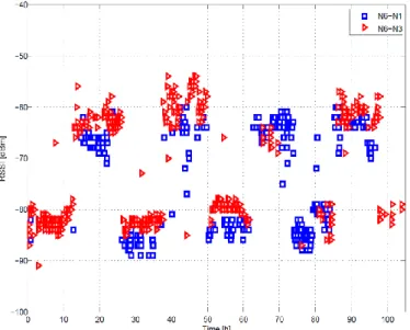
doors between the two communicating nodes are closed. Therefore, we have studied the evolution of RSSI of these “strange links” to determine if the two watertight doors were really closed when the links have been established. N6 for example, has N3 as primary parent node and N1 as secondary parent node. The connection between N6 and N3 is predicted as they are placed in adjacent rooms and possible closed watertight door may degrade their link quality. However, the connection between N6 and N1 is quite “strange” if the two watertight doors of the tank room were really closed. Fig. 5 shows the RSSI evolution of links (N6-N1) and (N6-N3). The
Figure 5. RSSI evolution of links between N6 and its main parent nodes, as a function of time.
RSSI levels of these two links are quite similar with a slightly lower value for (N6-N1). Two main levels of RSSI with a gap of 24 dB can be remarked for the two links. This gap corresponds to the supplementary attenuation due to the closure of the watertight door between the tank room and the rudder gear room. The value of this supplementary attenuation is similar to that found in P2P communication tests between adjacent rooms. Supposing that the door between N3 and N1 was closed, a minimum gap of 17 dB must appear between RSSI levels of (N6-N1) and (N6-N3) links. Hence, the similarity between the RSSI levels of these links proves that the door was opened when (N6-N1) has been established. The same procedure has been used to analyze the remaining “strange links”. The analysis has shown that at least one door was opened during the establishment of such links. Therefore, the conclusion of impossible communication between two nodes separated by two closed watertight doors remains valid.
V. CONCLUSION
We presented in this paper the results of measurements conducted on board a ferry-type boat to study the feasibility of wireless sensor networks on board ships. This particular environment is characterized by its metallic structure which may severely disturb the wireless communication. These experiments are one of the first tests conducted on board a ferry during sailings and under realistic conditions. We have started the study by conducting P2P measurements for the different configurations of communication between two nodes in a future shipboard environment (nodes in the same room, nodes in adjacent rooms or adjacent decks). The results of this first experiment helped us to draw some important engineering rules concerning the nodes placement in similar environments. Moreover, based on our preliminary results, we have tested a
WSN in the three lower decks during 105 hours. The results have shown very good network reliability. More than 97 % of packets of each sensor node have arrived successfully to the base station. Moreover, the network behavior, especially in parent selection, was consistent with conclusions drawn from P2P experiments and proved the viability of our node placement strategy. This study is one of the first steps towards replacing the wired shipboard monitoring system by the cost-effective WSN technology.
ACKNOWLEDGMENT
The authors would like to thank Brittany Ferries and Marinelec Technologies for the opportunity of conducting the measurements on board the “Armorique” ferry, and the “Pôle Mer Bretagne” and the Council of Brittany (“Région Bretagne”) for their financial support.
REFERENCES
[1] UNCTAD secretariat, “Review of maritime transport,” United nations conference on trade and development, Geneva, 2007.
[2] J. P. Lynch and K. J. Loh, “A summary review of wireless sensors and sensor networks for structural health monitoring”, The Shock and Vibration Digest, 38 (2), 2006, pp.91-128.
[3] D. Estes, T.B Welch, A.A. Sarkady, and H. Whitesel, “Shipboard Radio Frequency Propagation Measurements for Wireless Networks,” MILCOM2001, Military Communication Conference, Washington DC, USA, 2001, pp. 247–251.
[4] J. Yick, B. Mukkerjee and D. Ghosal, “Wireless Sensor Network Survey,” Computer Networks, 2008, Vol. 52, No. 12, pp. 2292–2330. [5] A. Nasipuri, R. Cox, H. Alasti, L. Van der Zel, B. Rodriguez, R.
McKosky, and J. A. Graziano, “Wireless sensor network for substation monitoring: Design and deployment,” in SenSys’08: 6th Intl. Conf. on Embedded Networked Sensor Systems, Nov. 2008, pp. 365–366. [6] G. Werner-Allen, K. Lorincz, J. Johnson, J. Lees, and M. Welsh,
“Fidelity and yield in a volcano monitoring sensor network,” in OSDI ’06: Proc. 7th symposium on Operating systems design and implementation, Nov. 2006, pp. 381–396.
[7] R. Szewczyk, A. Mainwaring, J. Polastre, J. Anderson, and D. Culler, “An analysis of a large scale habitat monitoring application,” in Sen- Sys’04: Proc. 2nd Intl. Conf. on Embedded Networked Sensor Systems, December 2004, pp. 214–226.
[8] P. Sikka, P. Corke, P. Valencia, C. Crossman, D. Swain, and G. Bishop- Hurley, “Wireless adhoc sensor and actuator networks on the farm,” in IPSN ’06: Proc. 5th Intl. Conf. on Information processing in sensor networks, April 2006, pp. 492–499.
[9] P. Bu-Geun, C. Seong-Rak, P. Beom-Jin, L. Dongkon, Y. Jong-Hwui, and B. Byung-Dueg, “Employment of wireless sensor networks for fullscale ship application”, In Proc. Int. Conf. Embedded and Ubiquitous Computing (EUC 2007), 2007, pp.113-122.
[10] T. Pilsak, T. Schröder, J. Eichmann and J. L. ter Haseborg, “Field test of a wireless sensor network inside the engine room of a vessel”, Hamburg University of Technology Institute of Measurement Technology, 2009. [11] H. Kdouh, G. Zaharia, C. Brousseau, G. Grunfelder, G. El Zein,
“ZigBee-based sensor network for shipboard environments”, Proc. of 10th ISSCS Romania, July 2011.
[12] Memsic Technology, “Xmesh user’s manual”,
http://www.memsic.com/support/documentation/wireless-sensor-networks/category/6-user-manuals.html.