Journal of Fundamental and Applied Sciences is licensed under aCreative Commons Attribution-NonCommercial 4.0 International License.Libraries Resource Directory. We are listed underResearch Associationscategory.
DIAGNOSIS OF ROTOR FAULT USING NEURO-FUZZY INFERENCE SYSTEM
H. Merabet1,*, T. Bahi2, D. Drici1, N. Halem3and K. Bedoud1
1
Research Center of Industrial Technologies (CRTI) P.O. Box 64, Cheraga, Algeria
2
Automatic and signals laboratory Annaba (LASA), Department of Electronic, University of Annaba
3
Department of Electrical Engineering, Faculty of Technology, University of El-Oued, P.O Box 789, El-Oued 39000, Algeria
Received: 14 September 2016 / Accepted: 18 December 2016 / Published online: 01 January 2017
ABSTRACT
The three-phase induction machine (IM) has a large importance and it is widely used as electromechanical system device, and because of their; robustness, reliability, and simple design with the well developed technologies. In spite of all cited advantages, the induction machines are suscptible to various types of electrical and mechanical faults that can lead easly to excessive downtimes, which can lead to tuge losses in terms of maintenance and production. This work presents a reliable approach for diagnosis and detection of broken bar faults in induction machine. The detection of faults is based on monitoring of the stator current signal. Also the calculation of relative energy value for each level of signal decomposition is determinated by using package wavelet, and this method will be useful as data input of Adaptive Neuro-Fuzzy Inference System (ANFIS). In the ANFIS approach the adaptive Neuro-Fuzzy inference system is able to identify the rotor of induction machine state with
high precision.This method is applied by using the MATLAB®/Simulink software.
Keywords: Induction machine; diagnosis; detection; Neuro-Fuzzy inference system.
Author Correspondence, e-mail:[email protected]
doi:http://dx.doi.org/10.4314/jfas.v9i1.12 ISSN 1112-9867
Available online at http://www.jfas.info
Journal of Fundamental and Applied Sciences is licensed under aCreative Commons Attribution-NonCommercial 4.0 International License.Libraries Resource Directory. We are listed underResearch Associationscategory.
DIAGNOSIS OF ROTOR FAULT USING NEURO-FUZZY INFERENCE SYSTEM
H. Merabet1,*, T. Bahi2, D. Drici1, N. Halem3and K. Bedoud1
1
Research Center of Industrial Technologies (CRTI) P.O. Box 64, Cheraga, Algeria
2
Automatic and signals laboratory Annaba (LASA), Department of Electronic, University of Annaba
3
Department of Electrical Engineering, Faculty of Technology, University of El-Oued, P.O Box 789, El-Oued 39000, Algeria
Received: 14 September 2016 / Accepted: 18 December 2016 / Published online: 01 January 2017
ABSTRACT
The three-phase induction machine (IM) has a large importance and it is widely used as electromechanical system device, and because of their; robustness, reliability, and simple design with the well developed technologies. In spite of all cited advantages, the induction machines are suscptible to various types of electrical and mechanical faults that can lead easly to excessive downtimes, which can lead to tuge losses in terms of maintenance and production. This work presents a reliable approach for diagnosis and detection of broken bar faults in induction machine. The detection of faults is based on monitoring of the stator current signal. Also the calculation of relative energy value for each level of signal decomposition is determinated by using package wavelet, and this method will be useful as data input of Adaptive Neuro-Fuzzy Inference System (ANFIS). In the ANFIS approach the adaptive Neuro-Fuzzy inference system is able to identify the rotor of induction machine state with
high precision.This method is applied by using the MATLAB®/Simulink software.
Keywords: Induction machine; diagnosis; detection; Neuro-Fuzzy inference system.
Author Correspondence, e-mail:[email protected]
doi:http://dx.doi.org/10.4314/jfas.v9i1.12 ISSN 1112-9867
NOMONCLATURE
Lb Leakage inductance of a rotor bar
Le Leakage inductance of a portion of a short-circuit ring
Lrp Principal inductance of a rotor mesh
Lsp Principal inductance of a stator phase
Lsr Mutual inductance between the stator phase and rotor mesh
Ms Mutual inductance between two stator phases
Mrr Mutual inductance between the stator phase and rotor mesh
Nr Number of rotor bars
Ns Number of stator turns
p Number of poles
d
R Resistance of a broken rotor bar
b
R Resistance of healthy rotor bar
e
R Resistance of a portion of a ring
Rs Resistance of a stator phase
a Distance between two rotor bars
θ Rotor position
1. INTRODUCTION
The induction machines (IM) are widly used in various fields, such as electrical drives system and main component of any industrial areas that involve production processes [1, 2]. In spite of their low cost, reliability and robustness, breakdown in electrical machines lead to failure of the entire production system which cause considerable financial losses. Consequently, early detection faults are very useful for avoiding failure and allow minimizing the downtime [3, 4]. Rotor faults are one of the most important faults of these machine types [5, 6].
The presence of broken rotor bar in the squirrel cage generates an asymmetry of geometric and electromagnetic of rotor circuit. As a result, this fault reduces the average value of the electromagnetic torque and increases the amplitude of oscillations in the rotor speed. Hence, these consequences generate mechanical vibrations and lead to abnormal function and maybe a total deterioration of the induction machine [7].
According to the literature, there are several techniques of the diagnosis and detection of electrical and/or mechanical faults in stator and/or rotor faults of electrical machines drives, especially, the methods that based on time domain or frequency domain techniques, which
have been suggested to detect stator failures. Many research efforts focused on frequency signature analysis for stator and rotor faults. These works were intersted to use different signals of machine such as; machine currents. The motor current signature analysis (MCSA), discrete wavelet transform (DWT), current envelope (CE), extended Park’s vector approach (EPVA), instantaneous power signature analysis (IPSA) and Short-Time Fourier Transform (STFT), etc, for extracting useful information from different signals [8, 9]. The artificial intelligences (IA) such as Expert Systems, Algorithm (GA), support victor machine (SVM), fuzzy logic system inference, artificial neural network (ANN) or combined structure techniques of artificial neural fuzzy interference system (ANFIS), combined Genetic and
ANFISs, are mostly used in the modern monitoring approaches of IM [10, 11]. Adaptive
Neuro-Fuzzy Inference System (ANFIS) is the adaptive networks that are functionally equivalent to fuzzy inference system (FIS). The Sugeno type ANFIS uses a hybrid learning algorithm (FIS and ANN) to identify parameters of Sugeno-type fuzzy inference system. It combines the least squares method and the back propagation gradient descent method for training (FIS) membership function parameters to emulate a given training data set. An ANFIS works by applying neural learning rules to identify and tune the parameters and structure of a Fuzzy Inference System (FIS). There are several features of the ANFIS which enable it to achieve great success for a large range of applications [12, 13]. Therefore, in order to increase the effectiveness and the reliability of the monitoring in the field of the induction machine supervision, our proposed approach is based on Neuro-Fuzzy inference system (ANFIS). In the aim to analyzing the stator currents for diagnosis and monotoring the faults, the global
mathematical model of induction machine is developed and simulated via software MATLAB®
/Simulink.
2. INDUCTION MOTOR MODEL
2.1. Multi meshes model of rotor broken bars fault
By the consideration that the studied induction machine has three phases concentric winding in stator circuit and Nrbars, the rotor is which can be described as Nridantical and equally
spaced rotor loops, each loop comprises tow rotor bars plus the connection parts of the end-rings between them as shown in figure 1 [14 ].
The global mathematical model of the squirrel cage induction machine is expressed by the following matrix [15]:
[ ] = [ ][ ] + ([ ][ ]) (1)
Where,the matrix of voltage and current are respectively given Eq. (2) and Eq. (3):
s r V V V (2) s r I I I (3) With, the system of different stator and rotor vectors matrix of voltage and currents is presented as follows: ⎩ ⎪ ⎨ ⎪ ⎧[ ] = [ ] [ ] = [ ] [ ] = [0 0 0 … 0] × [ ] = [ … … ] × (4)
The global resistance is expressed by the following matrix:
3 3 1 3 3 3 1 1 3 1 0 0 0 1 0 1 s N e r N r N r N N r e e N r R R R R N R R N r r r r (5)
Where, the matrix of stator and rotor resistances are respectivelly given by Eq.(6) and Eq.(7):
3 3 0 0 0 0 0 0 s s s s R R R R (6) Re/Nr Le/Nr Iek Irk Le/Nr Le/Nr Le/Nr Le/Nr Le/Nr Re/Nr Re/Nr Re/Nr Re/Nr Ir(k-1) Irk Ir(k-1) Rb Rb Ir(k+1) Lb
2 0 0 2 0 0 0 2 0 0 0 1 0 1 1 1 1 2 1 1 e b b b b r e rNr N b b b bk r e b b b b r R R R R R N R R R R R R N R R R R R N Nr Nr k Nr Nr r Nr Nr Nr Nr (7)The mutual inductance matrix between stator phases and rotor mesh can be written as following: 1 2 3 4 3 sr sr N r sr sr M cos ka M M cos ka M cos ka (8)
Where, k is ranging from 0 to Nr-1.
The inductances matrix of stator phases expressed by the relationship (9) is of the order (m,
m), where m=3: 3 3 s p s s S s s p s s s s p L M M L M L M M M L (9)
The inductances matrix of rotor Nrbars is expressed by the follows relationship:
2 2 2 2 2 2 2 2 e rp b rr b rr rr rr b r e rr b rp b rr b rr rr r e rr rr b rp b rr b rr R r rr e rr b rr rr rr b rp b r L L L M L M M M L N L M L L L M L M M N L M M L L L M L M L Nr Nr N M L M L M M M L L L N (10)
The modeling of a broken rotor bar can be modeled by increasing of its resistance value, so that the current transitory through it is devolves to zero, the new structure of rotor meshs circuit in broken rotor bar will be as shown in Figure 2.
Broken rotor bar
Re/Nr Le/Nr Iek Irk Le/Nr Le/Nr Le/Nr Le/Nr Le/Nr Re/Nr Re/Nr Re/Nr Re/Nr Ir(k-1) Irk Ir(k-1) Rb Ir(k+1) Lb
This is introduced in the matrix of resistances by the addition of the matrix of the rotor resistance [Rr] with the default matrix [Rd].
0 0 0 0 0 0 0 0 0 0 0 1 , 1 , 1 1 , , k k k k k k k k d R R R R R (11)In case of the broken bar, the resistance value of this bar is multiply by M = 103, with:
, = , = ( + 1). + 2. (12)
, = , = (− ). (13)
Therefore, the rotor cage resistance matrix, with considering of the broken bars fault is defined as following:
[ ] = [ ] + [ ] (14)
3. RESULTS AND DISCUSSION WAVELET PACKET METHOD 3.1. Decomposition level
The decomposition level of the approximation signal, which includes the left side band
harmonic, is the integer given by:
= / (2) (15)
For this approach, further decomposition of this signal has to be done, so that the frequency band [0 − ] will be decomposed in more bands. Usually, two additional decomposition
levels (that is, +2) would be adequate for the analysis [16]:
+ 2 = ( ) + 2 = 9 (16)
3.2. Energy level of the wavelet decomposition
The multilevel decomposition of the stator current was performed using Daubechies wavelet, the appropriate level of decomposition is calculated according to Eq. (14), when the faulty rotor is on the stator current phases of the induction machine appears, the faults information in stator current is integrated on each frequency band determined by the wavelet decomposition or in wavelet packet. Through calculated the associate energy of each nodes of decomposition level, for build one effective diagnosis and monitoring tools. The energy proper value for each
frequency band is defined by [17, 18]:
= ∑ , ( ) (17)
Based on the energy eigen value, the eigen vector is set up as:
= , , … … (18)
Where is the amplitude in each discrete point of the wavelet signal coefficient in the corresponding frequency band.
= ∑ (19)
The proper value T has information on the stator current signal for a machine behavior. In addition, the amplitudes of the deviation of some proper values indicate the severity of the faults, which makes a high quality of damaged bars supervision.
4. ADAPTIVE NEURO-FUZZY INFERENCE SYSTEM
ANFIS is a hybrid controller structure using fuzzy logic inference system and the architecture of a neural network having five-layer feed-forward structure [19-21]. Thus, the ANFIS offers the advantages of learning capability of neural networks and inference mechanism of fuzzy logic. The typical architecture of ANFIS has n inputs, one output (f), and m rules as illustrated in Figure. 3.
In the structure x, y, z and up to n are inputs, the output is f, the circle signify the fixed node functions and the square signify the adaptive node functions. This is a Sugeno type fuzzy system, where the fuzzy If-Then rules have the following form:
Rule1: If x is A1and y is B1,………..n is k1
Then f1= (p1x+q1y+r1z+……v1)
Rule 2: If x is A2and y is B2,………..n is k2
Then f2= (p2x+q2y+r2z+……v2).
Rule m: If x is Amand y is Bm,………n is km
Then fm= (pmx+qmy+rmz+……vm).
In this paper we are using the stator current signals as the input nodes, and the output is the estimated machine state for classified the rotor broken bars fault The ANFIS model provides the output value which can be used for advance decision making, also to go for preventive maintenance or to program of the maintenance. The suggested model for monitoring system is developed under MATLAB/Simulink. Database that collected from off-line is used to associate the energy to each node of decomposition level of stator current signal. The inputs are translated into 8 different Gaussian membership functions and 64 rule bases.
5. RESULTS AND DISCUSSION
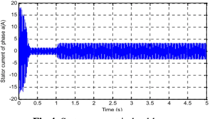
The Figure 4 and Figure 5 show, respectively, the stator current phase “Isa” in healthy case and the stator current phase “Isa “ in broken rotor bar with Zoom, the presented result
presented shows the appearing of the envelopes on the ends of the current .
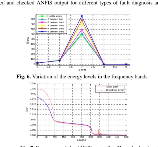
Figure 6 presents the variation of decomposition energy level of wavelet in the 16 frequency bands for healthy function case and with the presence of fault broken rotor bars in the induction machine. The ANFIS model generates eight input membership functions of Gaussian structure and it runs for 500 Epochs.
0 0.5 1 1.5 2 2.5 3 3.5 4 4.5 5 -20 -15 -10 -5 0 5 10 15 20 Time (s) St at or c ur re nt o f p ha se a (A )
Fig.4. Stator current in healthy case
Fig.5. Stator current in broken 5 rotor bars case 0 0.5 1 1.5 2 2.5 3 3.5 4 4.5 5 -20 -15 -10 -5 0 5 10 15 20 Time (s) St ato r c urr en t o f p ha se a( A) 1.8 2 2.2 2.4 2.6 2.8 3 3.2 3.4 3.6 -6 -4 -2 0 2 4
The error for the training and checking output is found to be 0.004 % as shown in Figure.7. The trained and checked ANFIS output for different types of fault diagnosis are shown in Figure. 8.
The input relationships or dependency for the ANFIS output are in addition analyzed. These are the unique characteristics of adaptive neuro-fuzzy inference system. The mapping is optimized by neuro adaptive learning techniques by fuzzy modeling procedure to learn information about the data set for monitoring the stat of induction machine in our case study.
5 5.5 6 6.5 7 7.5 8 8.5 9 0 100 200 300 400 500 600 700 800 900 Bands En erg y Healty case 1 broken bar 2 broken bars 3 broken bars 4 broken bars 5 broken bars
Fig. 6. Variation of the energy levels in the frequency bands
Fig. 7. Error curve of the ANFIS controller (Rotor broken bars) 0 50 100 150 200 250 300 350 400 450 500 0.004 0.006 0.008 0.01 0.012 0.014 0.016 0.018 0.02 0.022 0.024 Epoche Er ro r Train Error Checking Error
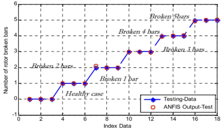
Fig.8. Training, Testing and Checking Output for the ANFIS controller (Rotor broken bars)
0 100 200 300 400 500 600 0 1 2 3 4 5 6 Index Data Nu m be r o f r ot or b ro ke n ba rs Training Data ANFIS Output Checking Data ANFIS Checking Output Broken 1 bar Healthy case Broken 2 bars Broken 3 bars Broken 4 bars Broken 5bars
To validate our network (shown the Fig.9), a test of recognition is carried out. The results are consigned in the following table (Show Tab.1).
Tabl 1. Numerical values of input-output for validate ANFIS
Inputs Outputs
Observations of the Error
x y Desired Estimated HEALTHY CASE 95.5056 366.6240 0.0000 0.0000 0.0000 96.5848 380.2702 0.0000 0.0000 0.0000 98.1150 405.8460 0.0000 0.0000 0.0000 1 BROKEN BARS 61.6177 351.4025 1.0000 1.0011 -0.0011 61.6177 366.5898 1.0000 0.9993 0.0007 65.3050 412.7210 1.0000 0.9987 0.0013 2 BROKEN BARS 56.7994 381.6860 2.0000 1.9998 0.0002 58.1560 398.6990 2.0000 2.0022 -0.0022 59.3361 416.9158 2.0000 1.9877 0.0023 3 BROKEN BARS 57.3547 434.1678 3.0000 3.0076 -0.0024 60.0000 480.0000 3.0000 2.9938 0.0062 62.5511 520.7533 3.0000 3.0009 -0 .0001 4 BROKEN BARS 53.0000 462.0000 4.0000 3.9895 0.0205 55.8730 500.4854 4.0000 4.0011 -0.0011 0 2 4 6 8 10 12 14 16 18 -1 0 1 2 3 4 5 6 Index Data Nu m be r o f r ot or b ro ke n ba rs Testing-Data ANFIS Output-Test Broken 5bars Broken 4 bars Broken 3 bars Broken 2 bars Broken 1 bar Healthy case
59.0201 550.6706 4.0000 3.9993 0.0007 5 BROKEN BARS 63.0000 552.0000 5.0000 4.8890 0.0210 65.8730 630.4051 5.0000 5.0000 0.0000 70.0111 645.0800 5.0000 5.9997 0.0003 6. CONCLUSION
In this paper, the development the healthy and the fault models of induction machine are presented; also the simulation of each models with application of the diagnosis approach for detection the presence of faults. The first part of this work presented the mathematical models of healthy and faulty machines with damaged rotor bars. In the second part; the ANFIS approach was used in aim to diagnose the broken bars in the induction machine. The adaptive neuro-fuzzy system inference indicator is based on the analysis of magnitude of energy level of the wavelet decomposition of stator current, this associate energy is used as inputs of ANFIS, and in addition, the off-line training and checking of ANFIS is used. The data bases are collected for different number of broken rotor bars. Finally, the performance of the ANFIS offered satisfactory results with high precision.
7. REFERENCES
[1] J. Seshadrinath, B. Singh, and B. Ketan Panigrah, “investigation of vibration signatures for multiple fault diagnosis in variable frequency drives using complex wavelets”, IEEE Transaction on power electronics, Vol. 29, No. 2, pp. 936-945. Feb 2014.
[2] C. da Casta, M. Kashiniwagi, M. Hugo. Marthias, “Rotor failure detection of induction motors by wavelet transform and fourier transform in non-stationary condiction”, Case studies in Mechanical Systems and signal processing, Vol. 1, pp. 15-26, 2015.
[3] F. Babaa, A. Khezzar, M.El Kamel Oumaamar, “Experimental investitgation and comparative study of inerturn short-circuits and unbalanced voltage supply in induction
[4] Halem N, Zouzou S. E ; Ghodbane H. Detection of static eccentricity fault in PSH induction motor by using external magnetic flux density . J Fundam Appl Sci., 2016, 8(3), 839-855.
[5] S.M. Shashidhara and P.S. Raju, “Stator Winding Fault Diagnosis of Three Phase
Induction Motor by Park’s Vector Approach”, Internatonal Journal of Advance Research
In Electircal Electronics and Instrumentation Engineering, Vol. 2, pp. 2901-2906, Issue, 7, July. 2013.
[6] S.S. Moosavi, A. Djerdir, Y. Ait-Amirat, D. A. Khaburi,, “ ANN based fault diagnosis of permanant magnet synchronous motor under stator winding shorted turn”, Electrical power system Research Vol 125, pp 67-82, 2015.
[7] A. Singh, B. Grant, R. DeFour, C. Sharma, S. Bahadoorsingh, “A review of
induction motor fault modeling,” Electric Power Systems Research, Vol 133,
pp 191–197, 2016.
[8] Houssin El Bouchikhi, Vincent Choqueuse, Mohamed Benbouzid, “Induction machine
faults detection using stator current parametric spectral estimation,” Mechanical Systems
and Signal Processing, Vol 52-53, pp 447–464, 2015.
[9] X. zhang, Y. liahg, J. Zhou, “a novel bearing fault diagnosis model integrated permutation entropy, ensemble empirical mode decomposition and optimized SVM”, Measurement, Vol 69,pp164–179. 2015.
[10]H. Eristi, “Fault diagnosis system for series compensated transmission line based on wavelet transform and adaptive neuro-fuzzy inference system”, Measurement, Vol 46, pp 393–401. 2013.
[11] P. Subbaraj, B. Kannapiran, “ Fault detection and diagnosis of pneumatic valve using Adaptive Neuro-Fuzzy Inference System approach”,Applied Soft Computing, Vol 19, pp, 362-371, 2014.
[12] R. Chandralekha, D. Jayanthi, “Diagnosis of Faults in Three Phase Induction Motor
using Neuro Fuzzy Logic”, International Journal of Applied Engineering Research ISSN
[13] R. N. Dash and B. Subudhi, “Stator inter-turn fault detection of an induction motor using neuro-fuzzy techniques”, Archives of Control Sciences, Vol. 20, No. 3, pp. 363–376, 2010.
[14]Y. Soufi, T. Bahi, M.F. Harkat, H. Merabet, “Diagnosis and detection of induction-motor dynamic eccentricity fault”, ELECTROMOTION, Vol. 18, No. 3, pp.125-132, 2011. [15] Pu. Shi, zheng chen, Y. Vagapov, Z. Zouaoui , “A new diagnosis of broken rotor bar
fault extent in three phase squirrel cage induction motor”, Mechanical System and Signal Processing, Vol 42, pp 388-403, 2014.
[16] N Lashkari, J Poshtan, HF Azgomi,“ Simulative and experimental investigation on stator winding turn and unbalanced supply voltage fault diagnosis in induction motors using Artificial Neural Networks”, ISA Transactions, Vol 59, pp 334-342, 2015.
[17] K. Moin Siddiqui, K. Sahay, V.K.Giri, “Health Monitoring and Fault Diagnosis in
Induction Motor”, International Journal of Advanced Research in Electrical, Electronics
and Instrumentation Engineering Vol. 3, January 2014.
[18] K. Moin Siddiqui and V.K.Giri,“ Broken Rotor Bar Fault Detection in Induction Motors
using Wavelet Transform”, Int. Conf Proc, IEEE, Computing, Electronics and Electrical
Technologies (ICCEET), pp. 1-6, Chennai, India, March, 2012.
[19] A. Bouzida, O. Touhami, Abddelli, Application of the wavelet technique to the fault
diagnosis of the cage rotor asynchronous machine”, Rer N, Vol. 15, No. 4, pp. 549-557,
2014.
[20] Haitham Abu-Rub, S. M.Ahmed , Shady S. Refaat, Atif Iqbal, “incipient bearing fault detection for three phase bruchless DC Motor Drive usin ANFIS”, IEEE, 2011.
[21] S. M.Ahmed , Haitham Abu-Rub, Shady S. Refaat, Atif Iqbal, “Diagnosis of Stator Turn-to-Turn Fault and Stator Voltage Unbalance Fault Using ANFIS”, International Journal of Electrical and Computer Engineering (IJECE) Vol.3, No.1, , pp. 129-135, February 2012.
How to cite this article:
Merabet H, Bahi T, Drici D, Halem N and Bedoud K. Diagnosis of rotor fault using neuro-fuzzy inference system. J. Fundam. Appl. Sci., 2017, 9(1), 170-182.