Titre:
Title:
An aerodynamic method for the analysis of isolated horizontal-axis
wind turbines
Auteurs:
Authors
: Christian Masson, Idriss Ammara et Ion Paraschivoiu
Date: 1997
Type:
Article de revue / Journal articleRéférence:
Citation
:
Masson, C., Ammara, I. & Paraschivoiu, I. (1997). An aerodynamic method for the analysis of isolated horizontal-axis wind turbines. International Journal of Rotating Machinery, 3(1), p. 21-32. doi:10.1155/s1023621x97000031
Document en libre accès dans PolyPublie
Open Access document in PolyPublieURL de PolyPublie:
PolyPublie URL: https://publications.polymtl.ca/3667/
Version: Version officielle de l'éditeur / Published versionRévisé par les pairs / Refereed Conditions d’utilisation:
Terms of Use: CC BY
Document publié chez l’éditeur officiel
Document issued by the official publisher
Titre de la revue:
Journal Title: International Journal of Rotating Machinery (vol. 3, no 1)
Maison d’édition:
Publisher: Hindawi
URL officiel:
Official URL: https://doi.org/10.1155/s1023621x97000031
Mention légale:
Legal notice:
Ce fichier a été téléchargé à partir de PolyPublie, le dépôt institutionnel de Polytechnique Montréal
This file has been downloaded from PolyPublie, the institutional repository of Polytechnique Montréal
Reprints available directly from the publisher Photocopying permitted by license only
under license by Gordon and Breach Science Publishers Printed inMalaysia
An
Aerodynamic
Method for the
Analysis of
Isolated
Horizontal-Axis Wind Turbines
CHRISTIAN MASSON*,IDRISSAMMARAandION PARASCHIVOIU
Bombardier AeronauticalChair,colePolytechnique, Montr6al, CANADA,H3C3A7
(Received 4 April1996)
Theaerodynamic analysisof a wind turbinerepresentsaverycomplextask since itinvolves
anunsteadythree-dimensional viscousflow.Inmostexisting performance-analysis methods,
wind turbinesare considered isolated sothat interference effects causedbyother rotors orby
the site topologyareneglected. Studyingtheseeffects in ordertooptimizethearrangement
and thepositioningof Horizontal-Axis Wind Turbines(HAWTs)on awind farm is one of the research activities of the Bombardier Aeronautical Chair. As a preliminary step in the
progress of this project, a method that includes some of the essential ingredients for the
analysisof windfarms has been developedand is presentedin the paper.Inthis proposed method, the flow field around isolated HAWTs is predicted by solving the steady-state, incompressible,two-dimensionalaxisymmetricNavier-Stokesequations.The turbine is
rep-resented by a distribution of momentum sources. The resulting governing equations are solvedusing aControl-Volume Finite ElementMethod(CVFEM). This axisymmetric
im-plementation efficientlyillustrates theapplicabilityandviabilityof theproposed methodol-ogy, by using aformulation that necessitates aminimum ofcomputerresources. The
axi-symmetric methodproduces performance predictions for isolated machines with the same level ofaccuracythan thewell-knownmomentum-strip theory. Itcantherefore be considered
tobe a useful tool forthedesignofHAWTs.Itsmainadvantage, however,is itscapacityto
predicttheflow in the wake which constitutes one of the essential features needed for the
performance predictions ofwind farms of dense clusterarrangements.
Keywords: WindFarm,WindPower,HAWT,NumericalMethod,Navier-StokesEquations
1.
INTRODUCTION
Aftersomeunsuccessful attemptsatconstructing and
operating very-large-scaleisolated windturbines, the
recenttendency is to construct wind farms of medi-um-sizemachines
(500
kW). The strategycurrentlyused during the conception of such wind farms con-sists in installing the turbines far from each otherin
orderto minimizethe interferenceeffects. This
prac-ticeresults invery sparse wind farms where the wind
energy potential of a site is inefficiently used. It is
justified by the performance losses associated to the
*Correspondingauthor. Tel.: (514)340-4582.Fax: (514)340-5917. E-mail:christian, [email protected]. 21
22 C. MASSONetal.
wake effects, which are significantin dense
arrange-ments.
However,
arelatively dense but staggeredar-rangement ofthe turbines is expectedto produce an
increase in the performance ofthe downstream tur-bines with respect to the isolated-turbine situation. This isdueto the beneficial venturieffects thatoccur
between two adjacent turbine wakes. The efficiency ofthe dense staggered cluster is not expected to be
significantly higher than that of the sparse
arrange-ment.
However,
for a given number of turbines, adense staggered cluster can be easily conceived that would occupy up to 25% less land than the sparse
arrangement. Notwithstanding the farmefficiency in-crease inducedby the venturi effects, a reduction of 25% of the wind farmarea canrepresentasignificant
economy in operating expenses. Furthermore, some oftheconstructionexpenses, suchasthe grading and
electric infrastructure costs, willbe reduced.
Various aerodynamic methods, appropriate for the conception ofisolated turbines, are available to de-signers (Gohard [1978], Paraschivoiu [1981],
Strick-land et al. [1980], Templin [1974], Wilson [1984]).
However, efficientandaccuratemethods for the
anal-ysisofadensecluster where the effects of the
three-dimensionalturbulentturbine wakesare includedare not available. The development ofa method that in-cludesthe essential ingredients for the successful
per-formancepredictions of wind turbines in adense
ar-rangementis theauthors’ main objective. In the
pro-posed method, the flow field of the wind farm is
predictedbysolving thesteady-state, incompressible,
three-dimensional Navier-Stokes equations. The tur-bines are represented by distributions ofmomentum sources, a technique introduced by Rajagopalan
[1984]and Rajagopalan andFanucci [1985].This is a
general formulationwhich can be applied, in
princi-ple,tohorizontal-axis andvertical-axis windturbines
andcaninclude the effects ofhubs, towers, and local
topography. The Navier-Stokes equations are solved
using the three-dimensional Control-Volume Finite
Element Method (CVFEM) of Saabas and Baliga
[1994].
The developmentof thismethodis stillin itsearly
stage, and the paper is aimed at presenting the
progressand atdemonstrating theapplicabilityof the
proposed method along with its capacity to analyze
the performances of wind farms. The mathematical
model and numerical method described in the"paper
are atwo-dimensional axisymmetric formulation
ap-plicable to isolated
HAWTs.
This implementation isused in thepapertodemonstrate theapplicabilityand
viabilityof theproposed methodology atmuchlower
CPUcosts than a fullythree-dimensional
implemen-tation. Several aspects related to the numerical
solu-tionof the mathematical model, suchas(i)the
appro-priate extent of the computational domain, (ii) the
grid spacing needed to obtain accurate performance
predictions, and(iii) the optimum choice of the vari-ouscontrolparameterstoobtainconvergedsolutions,
canalso be studiedmoreefficiently using the axisym-metric formulation. Comparisons between the
perfor-mancepredictions obtainedwiththeproposed
formu-lation and those of the momentum-strip theory are
presented to illustrate the accuracy of the proposed
methodology. Comparisons with experimental data
arealso included.
2.
GOVERNING EQUATIONS AND ROTOR
REPRESENTATION
The flow around an isolated
HAWT
is governed bythe unsteady three-dimensional Navier-Stokes
equa-tions whichhavetobesolved in a.domainwith
mov-ingboundaries. Analytical solutions of such a
prob-lem are hardly possible while numerical solutions
represent a formidable task on today’s computers.
However, a more tractable model producing
mean-ingful results canbe obtained bytime-averaging the
governing equations and byrepresenting the turbine
with momentum sources.
The derivationofthe,gov.erning equations
andmo-mentum sources is based on time-averaging tech-niques and the blade-element theory. The interested readerisreferred totheworks ofRajagopalan [1984]
and Rajagopalan and Fanucci [1985] for a detailed
derivation of the source terms ofvertical-axis wind
turbines.Inthecaseof horizontal-axis wind turbines, ofinteresthere, the derivationisvery similarand the
reader is referred to Fig. 1 for the definition of the
various parameters involved in the evaluation ofthe
momentum sources.
In steady-state, laminar, two-dimensional
axisym-metricflow aroundanisolated
HAWT,
themathemat-ical model consists ofa set offour differential
equa-tions: a continuity equation and three momentum
equations. The four dependent variables are
P
(hav-ing the components u, v, and w in the x, r, and 0directions) and p. The fluiddensityis represented by
p, anditsdynamic viscosityby ta.Theturbine is
com-posed of B blades having a coning angle y and a
chord c that can vary along the blade. The turbine rotational speedis f.
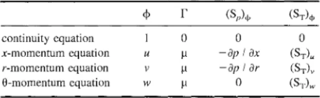
Theflow around anHAWTcan berepresented by
the following generalformulation:
V.(I3V+)--
V.FV+
-ff(Sp)qb
q--(ST)
+
(1)Theappropriate governingequationscanbeobtained
from
Eq.
(1) by defining the dependent variable,thediffusioncoefficient,
F,
andthevolumetric sourceterms,
(Sp)+
and(ST)+,
accordingto TableI,
where(ST)
K(UC
D+ WCL)
cos(2)
(ST)
-K(UC
DWCL)
sin3’(3)
(ST)
K(UC
LWCD)
(4)BVrelcAg
K -p(5)
2Vcv
Wre
/U
2q- W2(6)
U ucos/- v sin/ (7)w
rf- w (8,)Thesource terms
(ST)u, (ST)v, (ST)
arethe x-,r-,and0-component of the mutual time-averaged force,
ex-ertedby the fluid andthe blades on one another, per
unit volume ofthe fluid. They will be referredto as
the momentum-source terms.
CL
andCD
are the liftanddragcoefficients oftheblade-defining airfoiland
TABLE SpecificFormsof theGeneralEquation
+
F (Sp)b (ST)+continuity equation 0 0 0 x-momentumequation u ! --Op OX (ST) r-momentumequation v a -Op Or (ST)
0-momentum equation w p 0 (ST)w
are, ingeneral,functions of theangleof attackoand the local Reynolds number Re In the proposed
model, these coefficientscanbe taken fromeither
ex-perimentaldataornumerical resultsobtained overthe
appropriate two-dimensional airfoil.
Inthe aboveequations, Vcvisthe control volumeto
which the conservation principles have beenapplied,
and Af corresponds tothe blades length thatcrosses
thiscontrol volume.Itis tobe noted thatAfis zeroin
the region of the flow which is not crossed by the blades. Consequently, the momentum-source terms are non-zeroonlyin theregion of the flow crossedby
the turbineblades.
The mathematical model described in this section
has been obtainedby considering laminarflow. This
assumptionis difficulttojustifyphysically, sinceit is
well known that thewake ofawind turbine is turbu-lent. Nevertheless, theproposedmathematical model still includes someof the essential elements for
accu-rateperformancepredictions ofwindfarms. The
ma-jor features of theproposedmodelare (i)its capacity
to model the details of the wake behindtheturbines
and (ii) its implicit introduction of the interferences
between the rotors. The interferences are due to nu-merous effects such asthepressurevariationand the
blockage phenomenon.
In this early stage of development, the
laminar-flow assumption is used in order to emphasize the
various aspects relatedtothe windturbinemodelling without introducing uncertainties inherentto the
tur-bulence models. It is demonstrated in the RESULTS
Section thataccurateperformance predictionscan be
obtained using the laminar-flow assumption in the
caseofisolatedHAWTs since theirperformancesare
not highly influenced by the details oftheir wakes.
However,
when a turbine is located behind another, the turbulent wake has to be consideredin order to24 C.MASSONetat. /
--
Blade FIGURELift/
Dra
SECTION
A-A’
RotorGeometricParameters.
U
obtain accurateperformancepredictions of the
down-windturbine.
3.NUMERICAL
METHOD
The proposed numericalmethod is aCVFEM based
on the primitive-variables, co-located, equal-order
formulation of Masson et al. [1994]. Detailed de-scriptions ofthis CVFEM, pertaining to the
simula-tionof particulatetwo-phaseflows and internal
three-dimensional turbulent flows, are available in the works ofMasson [1993] and Saabas [1991]. There-fore, for sake of conciseness, only the aspects
rele-vant tothe successful simulation of theflow arounda windturbine arepresented inthis section.
3.1 Interpolation of in Convective
Term
In the derivation of algebraic approximations to
sur-face integrals of the convective fluxes, two different
interpolation schemes for
+
werepresented bySaabas[1991]: the FLow Oriented upwind scheme (FLO);
anda
MAss
Weighted upwind scheme (MAW).The FLO scheme is based on the earlier work of Baliga and Patankar [1980,1988]. The interpolation
function used in this scheme
responds
appropriatelyto an element-based Peclet number and to the direc-tion of theelement-averaged velocity vector. In
pla-nartwo-dimensionalproblems that involve
acute-an-gled triangular elements and relatively low element Peclet numbers, Saabas and Baliga [1994] have
proventhattheFLO schemecan be quite successful.
If high values of the element Peclet number are
en-countered, however,theFLOschemecanleadto
neg-ative coefficients in the algebraic discretised
equa-tions (Saabas and Baliga[1994]) andthis difficultyis
compoundedwhenobtuse-angledtriangular elements
areused. The donor-cellscheme of Prakash [1987]is oneway of ensuring positive coefficients: in this
ap-proach,the value ofa scalarconvected outofa
con-trol volume, across its surface, is set equal to the valueof the scalaratthe node within the control
vol-ume. This approach guarantees positive coefficients, but takes littleaccount ofthe influenceof the direc-tionof theflow. Thusit ispronetoconsiderable false diffusion(Prakash 1987]).
TheMAW schemeis based on the
positive-coeffi-cient schemes of Schneider and Raw [1986]. It en-sures, atthe element level, that the extent to which
thedependentvariableat anode exteriorto acontrol
volume contributes to the convective outflow is less
than orequalto its contribution tothe inflow by
con-vection. Thus, it is a sufficient condition to ensure
terms add positively to the discretised equation. It
should be noted that the MAW scheme takes better
account ofthe influence of the direction of the flow than thedonor-cell scheme ofPrakash [1987],so itis
less prone to false diffusion. Details ofthe
formula-tionoftheMAWschemearepresentedinthe workof Saabas 1991].
In problems with acute-angledtriangular elements
and relatively low element Peclet numbers, the FLO
scheme is more accurate than the MAW scheme.As
was mentioned earlier, however, when high element Peclet numbers are involved, especially in
conjunc-tion with obtuse-angled elements, the FLO scheme
produces negativecoefficientsinthe discretised
equa-tions. Negative coefficients in the’ discretized
equa-tions canleadto convergence difficulties when
itera-tive solutionalgorithms, suchasSIMPLEorits
vari-ants (Patankar [1980]) and CELS (Galpin et al.
[1985]),thatusesegregatedorcoupled equation
line-by-line iterative algorithms to solve the linearized
setsofdiscretisedequations, areused.
Inthenumerical solutionof the flow aroundawind
turbine, a fine grid has to be used in the immediate
vicinityof therotorinordertocapture thelarge
vari-ations of the flow properties. The grid size is then
increased as the distance to the turbine increases.
This coarseningis appliedin orderto keepa
reason-able number ofgrid points while ensuring the appli-cation of the boundary conditions to be far enough
from therotor. Theuseof suchcoarsegrids resultsin
large Pecletnumbers sincethese are directly
propor-tional to the grid size.
Convergence
difficulties wereencountered during the simulations presented in this
paperwhentheFLOschemewasused.Therefore,the
MAW
scheme has been usedtoproduceall the resultspresented in this paper and its application is
recom-mended for the successful solution of the flow around
a wind turbine.
related velocities (u
m,
vm),
as afunction ofapseudo-velocity and a pressuregradientterm:
(9)
where t/, and 9are thepseudo-velocities, andd", andd arecalled thepressure-gradientcoefficients.These expressions come directly from the discretised mo-mentum equations. However, instead of using the
control-volume-averaged pressure gradient, the
ele-mental pressure gradient is used to compute the mass-flow related velocity in each element. This
pre-ventstheoccurrenceof spuriouspressureoscillations
in theproposed CVFEM.
3.3
Momentum-Source Term
Linearization The momentum-source term,(ST)
+
is expressed inthe followinggeneralform (Patankar [1980]):
(ST)
+
(ST)
C q-(ST)p+
(lO)In
each triangular element, the values of(ST)c
and(ST)p are stored at the vertices, and are assumed to
prevailoverthecorresponding portions of the control
volumes within that element. Whilethe volume
inte-gration of themomentum-source term is straightfor-ward,itsproperlinearizationis crucialtoensure
con-vergence of the overall algorithm, especially in the
contextofthe segregatediterative solutionalgorithm
used in this work. The linearization consists in the specification ofappropriate expressions for
(ST)c
and(ST)p"
The momentum-source term canbe linearized
ex-plicitly ineach iteration:
3.2
Mass
FlowRate InterpolationThemassflowrate iscalculated usingaspecial treat-mentborrowed from the works of Prakash and
Patan-kar [1985] and Saabas and Baliga [1994]. This
spe-cial treatment consists in expressing the mass-flow
(ST)
C(ST)+
(ST)
p 0 (11) where the superscript * means that the source termhasbeenevaluated using the flowpropertiesobtained at the previous iteration. Implementation ofthis
lin-earization in the segregated iterative algorithm used in this work resultedin severeconvergence problems
26 C.MASSONetal.
for highly loaded wind turbines.
In
such conditions, the value of the momentum-source terms becomelarge, and the resulting momentum equations are
source-dominated. This results in very slow
conver-gence rates, and, sometimes the segregated iterative
algorithm even diverges. In an effort to improve the robustnessof the iterative solutionalgorithm, the fol-lowing treatmentis proposed:
(ST);
(ST)
C 0(ST)
p+,
(12)This linearization has proven to be much less prone
to convergence problems than the explicit
lineariza-tionexpressed by
Eq.
(11).3.4Boundary Conditions
The computational domain consists ofa simple
cyl-inder that includes the wind turbine. Boundary con-ditionshavetobeprescribedonthethreefacesofthis
cylindrical domain.
Inlet Boundary: The inlet boundary is a r-0 plane
located upstream of the wind turbine. In this plane,
the three velocity components are given by the known freestream wind speed while the pressure is
calculated from the discretisedcontinuity equations.
3.5 Overall SolutionAlgorithm
The discretisedequationsforma set ofcoupled non-linear algebraic equations. Inthis work, the iterative
variable adjustment procedure proposed by Saabas and Baliga [1994]isusedtosolve theproposed math-ematical model. Thisprocedureis akinto SIMPLER
(Patankar
[1980])
without the pressure correctionequation. In order to facilitate implementation and
testing of the proposed method, structured grids are
used. Thus, a line Gauss-Seidel algorithm based on
thetridiagonal matrixalgorithmareusedtosolvethe
discretisedequationsfor p, u, v, andw.
The momentum-source linearization proposed in
this work can lead to large differences between the
values of the two pressure-gradient coefficients. In
the case of an horizontal-axis wind turbine
com-pletely containedwithina r-0 plane, for example, d"
is typically much smaller than d
.
This largediffer-ence in the values of the pressure-gradient
coeffi-cientsleadstodifficultiesinensuring the overallmass conservation since the streamwise pressure gradient
has a negligible effect in the discretised pressure
equations. This difficulty is alleviated by prescribing
a relatively large number of iterations in the line
Gauss-Seidel algorithm used for the solution of the discretisedpressure equations.
4.
RESULTS
Outlet Boundary: The outlet boundary is a r-0planelocated downstream of the wind turbine.Inthis
plane, the pressure is assumed to be uniform and
given while the three velocity components are
com-puted from the discretised momentum equations
ob-tained using the outflow treatment of Patankar
[980].
Top
Boundary: This is acurved surfacelocatedat aradial distance far from the wind turbineblade tip.In
this plane, the velocityis set to its freestreamvalue.
Pressureis calculated from the discretisedcontinuity
equations.
The results presented in this section are aimed at
demonstrating the capacity of the proposed
method-ology to accurately predict the performances of
iso-lated
HAWTs,
and to analyse wind farms. To thiseffect, the details of the computed flow field in the
vicinity of an isolated
HAWT
are shown, andcom-parisons between the predictions of the proposed
method, those of the well-known momentum-strip
theory,and experimental data whenavailable are
pre-sented. Furthermore, the following aspects related to
thesuccessful numerical solutionof the mathematical model arestudied: (i) the determination of the
obtain acomputational-domain independent solution,
and(ii)the sensitivityoftheperformancepredictions
with respect to thegrid size.
The simulationspresentedin this sectionhave been realizedfor two
HAWTs:
(i) theNASA/DOEMod-0 100-kW ExperimentalHAWT
(Puthoff and Sirocky[1974]) operating at arotational speedof 40rpmand
ablade pitch angle of 3
,
and (ii) theINTA Experi-mental rotor(Hernandez andCrespo
[1987]) operat-ing at a rotational speed of 1500 rpm and a blade pitch angleof 9.54.1
Extent
of the ComputationalDomainA
detailed study of the behaviour of powerpredic-tions with respect to the size of the computational
domainhas been undertakeninordertodeterminethe
minimum extentof the computationaldomainneeded
to produce relevant performance predictions for
HAWTs.
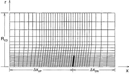
Inthecase of thesimulation of theaxisym-metric/swirling model, the size of the computational
domain is characterized by three length parameters,
namely
Axue, AXDN,
andRCD.
These lengthparame-ters arepresentedin Fig. 2 whichillustrates the grid
topology. Itis to be noted that the grids used in the
axisymmetric/swirling simulations were much finer
than theone shown in Fig. 2.
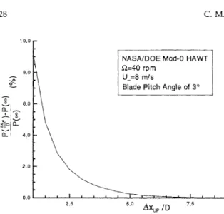
Figs. 3-5 show the results of the behaviourof the
performance prediction with respect to the extent of
the computational domain.These graphs present the
variation of the difference between the performance
prediction at a finite value of one of the length
pa-rameters (denoted by either
P(Axup
),P(AXDN),
P(RcD))
and the power predicted for a very largevalue of the correspondinglengthparameter(denoted byp(c)), asafunctionofaspecificlengthparameter.
Thelengthparameters have beennondimensionalized
with respectto the rotor diameterD. The grids used were ofuniformtype.withequalgridspacinginther
andxdirections.Thisanalysis has been undertakenat
themostcriticaltip speedratioTSRwhich isbelieved
tobe the TSR corresponding to themaximumpower
coefficient
Cp.
Thepower coefficient is definedbyP
ce
3)
2
where P is the mechanical power,
U
is the freestream wind velocity, and R is the rotor radius.The operational condition at which the maximum
powercoefficient occurs isthe mostcritical situation
since it corresponds to the regime where a greater
portion of the energy available in the flow is
ex-[::CD
r
T
Il_
AXup
--lJ-"
AXDN
---1
28 C. MASSONetal. I0"0
I
8.0 .o 4.0NASA/DOEMod-0HAWT D.=40rpm
U.=8m/s
BladePitchAngle of 3
FIGURE3 Variationof the Performance PredictionwithRespect
toAXup.
tractedbytherotor. Forablade pitchangleof 3 and
a rotational speed of 40 rpm, the freestream wind
speed at which the maximum
Cp
is reached for theNASA/DOE Mod-0 rotor is near 8 rrds. This study
hasrevealed that the power predictions ofanisolated rotor aresignificantly influencedbythelengthofthe computational domain upstream of the rotor (i.e.
AXup)
and the positionoftheconstant-radiusbound-ary (i.e.
RcD).
Based ontheresultspresentedin Figs.3 and5,
AXup/D
7.5 andRcD/D
4.0 seems tobelarge enoughto produce performance predictions
in-dependentoftheextentofthedomain.Forthe
down-stream extent of the computational domain, a much
0.50
NASA/DOE Mod-0HAWT
D,=40rpm
U.=8m/s
BladePitchAngle of 3
I--2.0 4.0 8.0
Axo
DFIGURE 4 Variationofthe PerformancePredictionwithRespect
to
AXDN.
0.0
1.500 3.000
NASA/DOEMod-0HAWT D.=40rpm
U.=8m/s
BladePitchAngle of 3
1, 4.500 6.000
RcD/D
FIGURE5 Variationofthe PerformancePredictionwithRespect
toRCD.
smaller value can be used. Fig. 4 suggests that
AXDN/D
4.5 is more than sufficient. These values oftheextentofthe computational domain have beenusedtoproducethe resultspresentedin the remainder
of this section.
4.2 GridDependence Study
Fig. 6 presents the difference between the
perfor-manceprediction obtained atagiven number of grid points
N,
P(N), and the grid-independentpowerpre-diction, p(c). This grid dependence study has been
3.0
NASA/DOEMod-0HAWT
.Q=40rpm
2.s
U.=8m/s
BladePitchAngle of 3
2.0
i/
Uniform grid1.0 0.5
0,0
2.5E4 5.0E4 7.5E4
N
FIGURE6 Variationof the Performance Prediction withRespect
realized on uniform grids with equal gridspacing in
the randx directions in order to facilitatethe
deter-mination of the grid-independent power prediction. Fig. 6 shows that the grid-independent solution is
reachednearN 25 000. Thisvery largenumber of grid points needed to obtain the grid-independent
powerprediction is due to the use ofuniformgrids.
However,
for practical calculations, nonuniform grids should be used in order to minimize the number of gridpoints needed. Using auniform and finegridinthe vicinity of therotoralongwith anexpanding grid
in the rest of the computational domain, it has been
possible to reduce the number of points needed to
obtain asolutionclosetothegrid-independentoneto
3 000(see Fig.
6).
Cp 0.40 0.35 0.30 0.25 0.20 0.15 0.10 0.05 0.00 5.0,,,
.=40!pro
Blade PitchAngle of 3 Proposed Method Momentum-StripTheory
7.5 10.0 12.5
TSR
FIGURE 8 Power Coefficient Predictions for the NASA/DOE Mod-0HAWT.
4.3 Comparisonswith the
Momentum
StripTheory andExperimental
Data
Figs. 7 and 8 show comparisons between the
perfor-mance predictions of the NASA/DOE Mod-0 100-kW Experimental
HAWT
produced by thepro-posedmethodologyand the results of the
momentum-striptheory. The agreement between thetwomethods
is good. This was to be expected since the factor
limiting theaccuracyofthe resultsistheuseof static
two-dimensional lift and drag coefficients, on which
both methods are based. As stated before, the main
motivation in developing the proposed method re-sides in its inherentmodelling of therotor/rotor,
ro-tor/ground,androtor/towerinteractionsandits
capac-itytoproducethedetails ofthe flowfield around the
turbines.
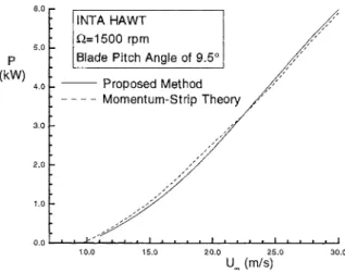
Figs. 9 and 10 present similar comparisons for the
case of the
INTA
ExperimentalHAWT.
In this case,theagreementisverygoodbetween thetwomethods.
Fig. 10 also showssomeexperimental
data.
Theper-formance predictions produced by the two methods
are in relatively good agreement with the measured
performances.
400
P (kW)
300
NASA/DOEMod-0HAWT
D,=40rpm
BladePitchAngle of 3
Proposed Method Momentum-StripTheory
7.5 10.0 12.s
U
(m/s) 15.0FIGURE 7 Power Predictions for the NASA/DOE Mod-0
HAWT. P (kW) 2.0 1.0 INTAHAWT O.= 1500rpm
Blade
Pitc___h
Angl_____e
of9.5___
Proposed Method
Fm
10.0 15.0 20.0 25.0 30.0
U
(m/s)30 C.MASSONetal.
Cp
INTA HAWT f=1500rpm
""-"
-’’-a- BladePtchAngle of9.5\
Proposed Method
Momentum-StripTheory
Experiments
TSR
FIGURE 10 PowerCoefficientPredictionsfor theINTA HAWT.
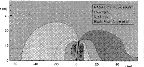
4.4 Predicted Flow Field
Using thenonuniform3 000-point grid, the flowfield
around the NASA/DOE Mod-0 HAWT has been
computed. The resulting pressure and velocityfields
in the vicinity of the rotor are presented in Figs. 11
and 12. These results illustrate the capacity of the
proposed methodology to produce the details of the
flowbehind a wind turbine, whichconstitutes one of the essential features for the successful analysis of
windfarms.
5.
CONCLUSION
Theideaof using theventurieffects inwindfarms is a new concept. More fundamental research is
re-quiredtodetermine its applicability.Forinstance, the
sensitivityof the cluster efficiencyto thewind
orien-tationis a crucialaspect relatedtothe viability ofthis
concept. The development of a method appropriate for the analysis of dense cluster arrangements
corre-spondstothe first step inthisfeasibilitystudy.Sucha
method can allow the determination of the optimum cluster arrangement, which is expected to be highly
relatedto a specific site (wind speedand orientation variations,topography, etc.). Furthermore, thedigital
versionof such a method representsapowerful tool for the designers of wind farm projects.
The methodpresentedin thispaper includessome
of the important ingredients needed for the successful analysis of dense cluster arrangements. The
imple-mentationofthismethod has beenrealizedunder the assumption of axisymmetric swirling flow. This
im-plementation has allowed to efficiently illustrate the
applicability andviability of the proposed
methodol-ogy byusing a formulationthat.necessitates a mini-mumof computer resources. Additional features have
tobeincludedin thismethodbeforeitsapplicationto
FIGURE Computed PressureFieldfortheNASA/DOEMod-0HAWT.
p-p_ (Pa) 7.0 5,0 3.0 1.0 -:3.0 -7.0 -11.0
(m)
15
NASA/DOEMod-O HAW
____-__.--____-, > ).=40 rpm
,Blade
PitchAngleof 3/
20
x (m)
FIGURE 12 ComputedVelocityFieldfor theNASA/DOEMod-0HAWT.
theperformancepredictions of wind farms. Thefully
three-dimensional formulation has to be imple-mented. Furthermore, an appropriate turbulence model should be selected and implemented in order
to obtain accurate performance predictions for
tur-bines located behind others. Nevertheless, the
axi-symmetric formulationproduces performance
predic-tions for isolated HAWTswith the same level of
ac-curacy than the well-known momentum-strip theory.
Itcanbe consideredtobeauseful tool for thedesign
of horizontal-axis windturbines.
Acknowledgement
Thisworkissupported bythe "Ministrede
l"Inergie
et des Ressources du Qudbec" through the
"Pro-gramme d’aide au d6veloppement des technologies
del’6nergie".The authors wouldlike toexpresstheir
gratitude to R.
E
Legault and J. E. Wade, from Kenetech Windpower, for the numerous helpful dis-cussions they havehad withthem. The results of themomentum-striptheoryhavebeen obtainedusing the
computer codedeveloped by TayebBrahimiandDan
Chocron, of the Bombardier AeronauticalChair.
References
Baliga, B.R.,Patankar,S.V., 1980.A NewFinite-Element
Formu-lation for Convection-Diffusion Problems, Numerical Heat Transfer,Vol. 3, pp. 393-409.
Baliga, B.R., Patankar, S.V., 1988. Elliptic Systems: Finite Ele-mentMethodII,inMinkowycz,W.J.etal. (Eds.),Handbookof NumericalHeat Transfer,Wiley,NewYork,Chap. 11, pp. 421-461.
Galpin,RE, VanDoormaal,J.R,Raithby,G.D., 1985.Solutionof the IncompressibleMassandMomentumEquationsby Applica-tionofaCoupledEquationLineSolver,Int.J.forNum.Meth.in Fluids, Vol.5,pp.615-625.
Gohard,J.D.,1978.Free Wake AnalysisofWind Turbine
Aerody-namics, TR 184-14, Massachusetts Institute of Technology,
Cambridge.
Hernandez,J.,Crespo, A., 1987. Aerodynamic Calculationof the Performance ofHorizontal Axis Wind Turbinesand Comparison withExperimentalResults,Wind Engineering,Vol. 11,pp. 177-187.
Masson, C., 1993. Numerical Prediction of Gas-Solid Particle FlowsoveraWideRangeofConcentration inIrregular
Geom-etries, Ph.D. Thesis,Dept. ofMech.Eng., McGill University, Montreal, Canada.
Masson, C., Saabas, H.J. and Baliga, B.R., 1994. Co-Located
Equal-OrderControl-Volume Finite-ElementMethod for
Two-DimensionalAxisymmetricIncompressibleFluidFlow,
Interna-tionalJournalforNumericalMethods in Fluids, Vol. 18, pp.
1-26.
Paraschivoiu, I., 1981. Double-Multiple Streamtube Model for DarrieusWindTurbines, SecondDOEWind Turbines
Dy-namics Workshop,NASA CP-2185, pp. 19-25.
Patankar, S.V., 1980. NumericalHeat TransferandFluid Flow, McGraw-Hill, New-York.
32 C. MASSONetal.
Prakash,C.,Patankar,S.V., 1985AControlVolume-Based Finite-Element Method for Solving theNavier-StokesEquations Using
Equal-Order Velocity-Pressure Interpolation, Numerical Heat Transfer,Vol. 8, pp. 259-280.
Prakash, C., 1987.Examinationof the Upwind (Donor-Cell)
For-mulation inControlVolumeFinite-ElementMethodsforFluid Flow andHeatTransfer,NumericalHeat Transfer,Vol. 11,pp.
401-416.
Puthoff,R.L.,Sirocky,RJ., 1974 Preliminary DesignofalO0-kW Wind TurbineGenerator,NASA TMX-71585.
Rajagopalan,R.G.,1984.InviscidUpwindFiniteDifferenceModel forTwo-DimensionalVertical Axis WindTurbines, Ph.D. Thesis,
WestVirginia University,Morgantown.
Rajagopalan, R.G., Fanucci, J.B., 1985. FiniteDifference Model for theVertical Axis WindTurbines, JournalofPropulsion and
Power,Vol. 1, pp. 432-436.
Saabas,H.J., 1991.A Control VolumeFiniteElement Methodfor Three-Dimensional,Incompressible, ViscousFluidFlow, Ph.D. Thesis,Dept. of Mech.Eng.,McGillUniversity, Montreal,
Can-ada.
Saabas,H.J.and Baliga,B.R.,1994. Co-LocatedEqual-Order Con-trol-Volume Finite-Element Method forMultidimensional,
In-compressible, Fluid FlowmPart I, Numerical Heat Transfer,
Vol.26B, pp. 381-407.
Schneider, G.E., Raw, M.J., 1986. ASkewed Positive Influence Coefficient Upwinding Procedure for Control Volume Based Fi-nite Element Convection Diffusion Computation, Numerical
Heat Transfer,Vol.9, pp. 1-26.
Strickland, J.H.,Webster, B.T., and Nguyen, T., 1980. A Vortex
ModeloftheDarrieusTurbine:AnAnalytical andExperimental Study, SAND79-7058,SandiaNationalLaboratories,
Albuquer-que.
Templin, R.S., 1974. Aerodynamic Performance Theoryfor the NRCVertical-Axis WindTurbine, LTR-160, NationalResearch CouncilofCanada, Ottawa.
Wilson,R.E.,Walker, S.N., 1984.PerformanceAnalysisof
ENERGY MATERIALS
Materials Science & Engineering for Energy Systems
Economic and environmental factors are creating ever greater pressures for the efficient generation, transmission and use of energy. Materials developments are crucial to progress in all these areas: to innovation in design; to extending lifetime and maintenance intervals; and to successful operation in more demanding environments. Drawing together the broad community with interests in these areas,Energy Materials addresses materials needs in future energy generation, transmission, utilisation, conservation and storage. The journal covers thermal generation and gas turbines; renewable power (wind, wave, tidal, hydro, solar and geothermal); fuel cells (low and high temperature); materials issues relevant to biomass and biotechnology; nuclear power generation (fission and fusion); hydrogen generation and storage in the context of the ‘hydrogen economy’; and the transmission and storage of the energy produced.
As well as publishing high-quality peer-reviewed research,Energy Materials promotes discussion of issues common to all sectors, through commissioned reviews and commentaries. The journal includes coverage of energy economics and policy, and broader social issues, since the political and legislative context influence research and investment decisions.
SUBSCRIPTION INFORMATION Volume 1 (2006), 4 issues per year
Print ISSN: 1748-9237 Online ISSN: 1748-9245 Individual rate: £76.00/US$141.00
Institutional rate: £235.00/US$435.00
Online-only institutional rate: £199.00/US$367.00 For special IOM3member rates please email
[email protected] EDITORS
Dr Fujio Abe NIMS, Japan
Dr John Hald, IPL-MPT, Technical University of Denmark, Denmark
Dr R Viswanathan, EPRI, USA
For further information please contact: Maney Publishing UK
Tel: +44 (0)113 249 7481 Fax: +44 (0)113 248 6983 Email: [email protected] or
Maney Publishing North America
Tel (toll free): 866 297 5154 Fax: 617 354 6875 Email: [email protected]
For further information or to subscribe online please visit
www.maney.co.uk
CALL FOR PAPERS
Contributions to the journal should be submitted online at
http://ema.edmgr.com
To view the Notes for Contributors please visit:
www.maney.co.uk/journals/notes/ema
Upon publication in 2006, this journal will be available via the Ingenta Connect journals service. To view free sample content online visit: www.ingentaconnect.com/content/maney
EW
FO
R
20
06
Internatfional Journal of
A
e
ro
spa
c
e
Eng
fin
e
e
r
fing
Hfindawfi Publfishfing Corporatfion
http://www.hfindawfi.com Volume 2010
Robo
Journal ot
fics
fH findawfi Publfishfing Corporatfion
http://www.hfindawfi.com Volume 2014
H findawfi Publfishfing Corporatfion
http://www.hfindawfi.com Volume 2014
Actfive and Passfive Electronfic Components
Control Scfience and Engfineerfing
Journal of
H findawfi Publfishfing Corporatfion
http://www.hfindawfi.com Volume 2014
Internatfional Journal of
Rotatfing Machfinery
H findawfi Publfishfing Corporatfion
http://www.hfindawfi.com Volume 2014 H
findawfi Publfishfing Corporatfion http://www.hfindawfi.com
Journal of
En
g
fin
e
er
fin
g
Volume 2014
Subm
fi
t
your
manuscr
fip
ts
a
t
h
t
tp
:
/
/www
.h
findaw
fi
.com
VLSI Desfign
Hfindawfi Publfishfing Corporatfion
http://www.hfindawfi.com Volume 2014
H findawfi Publfishfing Corporatfion
http://www.hfindawfi.com Volume 2014
Shock and Vfibratfion
H findawfi Publfishfing Corporatfion
http://www.hfindawfi.com Volume 2014
C
Advancesfiv
fi
l
Eng
finfinee
r
fing
AcousAdvancestficsfin and Vfibratfion
H findawfi Publfishfing Corporatfion
http://www.hfindawfi.com Volume 2014 H
findawfi Publfishfing Corporatfion
http://www.hfindawfi.com Volume 2014
Electrfical and Computer Engfineerfing
Journal of
Advancesfin OptoElectronfics
Hfindawfi Publfishfing Corporatfion
http://www.hfindawfi.com Volume 2014
The
Sc
fient
fific
Wor
ld
Journa
l
H findawfi Publfishfing Corporatfion
http://www.hfindawfi.com Volume 2014
Senso
JouHfindawfi Publrnafishfing Corporatl ofionfrs
http://www.hfindawfi.com Volume 2014
Modellfing & Sfimulatfion fin Engfineerfing
Hfindawfi Publfishfing Corporatfion
http://www.hfindawfi.com Volume 2014
H findawfi Publfishfing Corporatfion
http://www.hfindawfi.com Volume 2014
Chemfical Engfineerfing
InternatfionalJournal of Antennas and
Propagatfion
InternatfionalJournal of
H findawfi Publfishfing Corporatfion
http://www.hfindawfi.com Volume 2014 H findawfi Publfishfing Corporatfion
http://www.hfindawfi.com Volume 2014
Navfigatfion and Observatfion
InternatfionalJournal of
H findawfi Publfishfing Corporatfion
http://www.hfindawfi.com Volume 2014
Dfistrfibuted
Sensor Networks