HAL Id: hal-02538310
https://hal.archives-ouvertes.fr/hal-02538310
Submitted on 9 Apr 2020
HAL is a multi-disciplinary open access
archive for the deposit and dissemination of
sci-entific research documents, whether they are
pub-lished or not. The documents may come from
teaching and research institutions in France or
abroad, or from public or private research centers.
L’archive ouverte pluridisciplinaire HAL, est
destinée au dépôt et à la diffusion de documents
scientifiques de niveau recherche, publiés ou non,
émanant des établissements d’enseignement et de
recherche français ou étrangers, des laboratoires
publics ou privés.
Extracting the Inertia Properties of the Human Upper
Body Using Computer Vision
Dimitrios Menychtas, Alina Glushkova, Sotirios Manitsaris
To cite this version:
Dimitrios Menychtas, Alina Glushkova, Sotirios Manitsaris. Extracting the Inertia Properties of
the Human Upper Body Using Computer Vision.
Computer Vision Systems, pp.596-603, 2019,
�10.1007/978-3-030-34995-0_54�. �hal-02538310�
Upper Body Using Computer Vision
Dimitrios Menychtas1, Alina Glushkova1, and Sotirios Manitsaris1
Centre for Robotics, MINES ParisTech, PSL Universit´e Paris [email protected]
Abstract. Currently, biomechanics analyses of the upper human body are mostly kinematic i.e., they are concerned with the positions, ve-locities, and accelerations of the joints on the human body with little consideration on the forces required to produces them. Tough kinetic analysis can give insight to the torques required by the muscles to gen-erate motion and therefore provide more information regarding human movements, it is generally used in a relatively small scope (e.g. one joint or the contact forces the hand applies). The problem is that in order to calculate the joint torques on an articulated body, such as the human arm, the correct shape and weight must be measured. For robot manip-ulators, this is done by the manufacturer during the designing phase, however, on the human arm, direct measurement of the volume and the weight is very difficult and extremely impractical. Methods for indirect estimation of those parameters have been proposed, such as the use of medical imaging or standardized scaling factors (SF). However, there is always a trade off between accuracy and practicality. This paper uses computer vision (CV) to extract the shape of each body segment and find the inertia parameters. The joint torques are calculated using those parameters and they are compared to joint torques that were calculated using SF to establish the inertia properties. The purpose here is to ex-amine a practical method for real-time joint torques calculation that can be personalized and accurate.
Keywords: Computer Vision · Biomechanics · Upper Human Body · Inertia Properties.
1
Introduction
The science of motion and movements of the human body is called biomechanics and it has wide application to sports, ergonomics, and rehabilitation. As a field it shares a lot of the underlying principles with mechanical devices and specif-ically articulated robots. However, its most distinguishing characteristic is that it needs to consider the anthropometrics of each individual. Anthropometrics are the measurements of the human body (height, limb lengths, weight etc.) and they are different for every person. It is generally challenging and time-consuming to get these measurements, as a result it is more efficient to average them based on certain characteristics (gender, race etc). However, quite often,
2 D. Menychtas
the interest is in the individual performance, and therefore using standardized parameters obscures this individuality. There quite a few studies that provide such generic data. Both kinematic and kinetic average measurements are pub-licly available [1–3]. Those measurements have provided scaling factors (SF) to allow for the regression of the inertial properties based on a person’s height and weight. The earlier attempts to calculate the inertia parameters used cadavers. Once the technology became available, medical imaging was used to reconstruct the shape of the human body and calculate the inertia properties( [1–3], among others). Obviously, neither method is particularly practical to be incorporated in an experiment with larger scope or in a working environment where the need for real-time, or at least reasonably quick, results is crucial.
Though the SF can be reasonably accurate, no ground truth exists and the validation of the SF can be challenging [4]. On a more technical level, the more dependent a calculation is on the inertia parameters, the less personalized the results are going to be. This can explain, to a certain degree why joint torques are not used as often as one might expect.
This paper examines the possibility of using computer vision (CV) to extract the volumes of the segments of the human body to find the inertia properties. The joint torques during two simple motions of the right arm will be calculated using inertia properties from CV and SF.
2
Methods
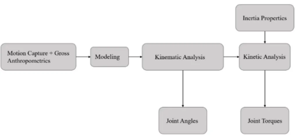
The inverse dynamics problem is when the joint motions of the human body are known and the forces that cause them are unknown. In general, a kinematic model of the human body and the tensors of inertia are required to solve the problem. The most efficient algorithm is the recursive Newton-Euler [5]. The basic components will be briefly discussed here, but note that each aspect has its own intricacies and it is impossible to cover all the material here. Fig 1 shows the basic steps of a biomechanical study.
2.1 Data Collection
For this work, the joint angles of an expert glassblower during crafting were recorded using an inertial measurement units (IMUs) suit (Nansense, Baranger Studios, Los Angeles, CA, USA). Standard RGB video was also recorded. At this point, the concept is shown. The recordings from the IMUs suit will provide the kinematic data, while the RGB video frames will be used to calculate the volumes of the body segments.
2.2 The Kinematic Model of the Human Body
The human body is a highly sophisticated structure that synchronizes different organ systems to generate motion. Those systems interact on a cellular level and produce an effect on a macroscopic scale. Each joint can move in up to
Fig. 1. The Flow Chart of the Standard Steps of a Biomechanical Analysis. “Gross Anthropometrics” can mean just the height and the weight of a person, or more specific measurements depending on the project
three Cartesian axes, with each axis contributing a degree of freedom (DoF) to the system. As such, it is important to establish the scope of the project and the DoFs the model needs to have. Certain segments of the body (e.g. shoulder complex) can be modeled in different ways, while still keeping the important aspects for each application.
In its most essential definition, the human body can be described mathemat-ically as a kinematic chain. The most elegant way to define complex kinematic chains is with the use of screw theory and the product of exponentials (POE). Proposed by Brockett [7], and described, among others, by Murray et. al [6], Selig [8], and Park & Lynch [9], this methodology defines each DoF as an axis, with respect to a global coordinate frame, about which a rigid body can rotate. The complexity of the mathematics involved does not increase with the number of DoFs. Even though it initially appears to be more complicated than other approaches (e.g. Denavit-Hartenberg parameters), more advanced robotic con-cepts, such as the Jacobian or the mass matrix, become easier to calculate and incorporate. For the scope of this work, such a model will allow for the calcu-lation of the joint torques using the same methodologies that are applied on manipulators.
In this paper, the model that is used is similar to the one Menychtas used [10]. The upper body is separated into seven segments. The torso, two upper arm segments, two forearm segments, and two hand segments, one in each side. The weight and the centers of mass for each segment are added for the kinetics calculations.
4 D. Menychtas
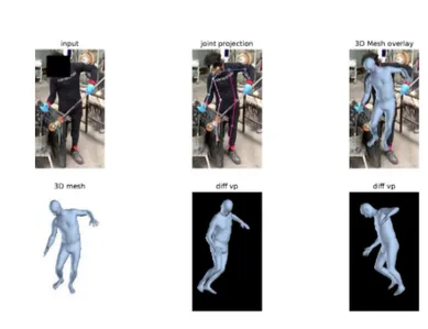
Fig. 2. A Glassblower During the Creation of an Item. HMR Identifies the Volume of his Body
.
2.3 Calculating the Tensors of Inertia
In this work, the tensors of inertia for each segment of the upper human body will be calculated in two ways. The first method will be to use the person’s height and weight along with the SF reported by Dumas et al. [2]. This method will interpolate the inertial properties of the participant with respect to the general population. The mass of each segment of the body is considered to be a percentage of the total weight, and the tensors of inertia are scaled according to the height and the segments’ weight.
The second method uses CV to extract the volumes of the body’s segments. More specifically, the Human Mesh Recovery (HMR) [11] is employed to produce a 3D mesh of the body. Static images are used to fit the mesh on the person’s body shape and posture. Fig. 2 shows an example.
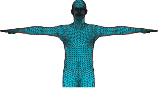
HMR uses the skinned multi-person linear model (SMPL) [12] as its foun-dation and performs its calculations on it. Since the kinematic data related to posture have been recorded from the IMUs suit, there is no need to try and ex-tract the joint angles from the mesh the HMR creates, only the volume is used here. Fig. 3 shows the mesh that was extracted in a T-pose.
Now that the 3D mesh is not distorted by the posture, each segment of the upper human body can be separated and the volume can be calculated. Parallelepiped bounding boxes are used to encapsulate the mesh’s volume(Fig 4). To increase accuracy, each segment uses more than one box. The density is assumed to be constant with a value of 985kg/m3, therefore the integral of the
Fig. 3. The 3D mesh extracted from HMR projected on a T-Pose
are calculated based on the center of mass and the weight that is measured. Using this method doesn’t require any additional input because all relevant data have been extracted from the video recordings
Fig. 4. The bounding boxes on the upper body
2.4 Experiment
A subject of 65kg and 1.73m participated in a series of motions to create an item made of glass. As it is standard practice, the person performed range of motion (ROM) tasks before the actual recordings, to create reference points for his motions. Analyzing the kinematic and kinetic results of the complete movements falls outside the scope of this paper. To limit the discussion on the
6 D. Menychtas
appropriate way to calculate the joint torques, only two ROM tasks will be examined.
For the first task, the person stood straight up and flexed his elbows all the way up and then down until he returned to the neutral posture. The process was repeated three times. The second task focused on shoulder rotation. The participant stood with his upper arm abducted parallel to the ground and the elbows flexed at 90o angle and the palms open. He rotated his upper arm until
his fingers were pointing upwards and then reversed the rotation until his fingers were pointing to the ground and then returned to the initial position. This task was repeated three times as well.
3
Results & Discussion
The torques are calculated using the inertia properties extracted by the two methods previously described but the motion files (joint centers and angles) are the same as well as the kinematic model. As a result, the differences on the resulting data are due to different inertia properties only.
-14 -12 -10 -8 -6 -4 -2 0 2 4 0 25 50 75 100 Joint T or qu es (Nm)
Task Duration (Percentage %)
Shoulder Rotation Joint Torques SF Joint Torques CV
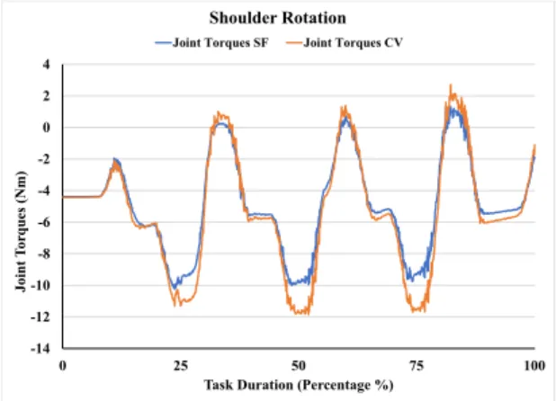
Fig. 5. Shoulder Rotation Torques
Fig. 5 shows the torques of the shoulder rotation calculated using SF and CV. As the arm rotates upwards, the torque is increased because the lever arm moves against gravity. As it goes down, the torque shows that the arm is moving in the negative sense. Both methods yield similar results even though the CV method appears to yield higher peaks and deeper valleys. Since the kinematics are the same, the only explanation is that the inertia properties are higher because the segments’ volumes and masses are larger.
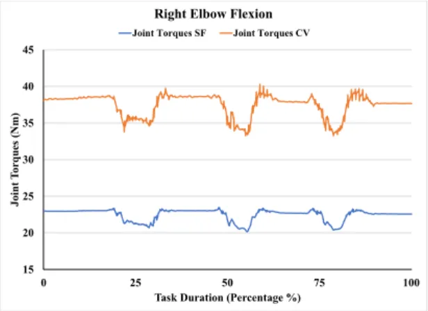
Fig. 6 highlights this even further. While the profile of the torques is the same in both cases, the magnitude is different. Unfortunately, neither methodology can be considered ground truth. The SF uses average scaling factors with the
assumption that the inertia properties will be close enough. The CV method, on the other hand is constrained by how accurately it can identify the human body and fit the 3D mesh on each person. Basically, both methods are almost accurate enough. As a result, it is very difficult to favor one method over the other without further experimentation.
15 20 25 30 35 40 45 0 25 50 75 100 Joint T or qu es (Nm)
Task Duration (Percentage %)
Right Elbow Flexion Joint Torques SF Joint Torques CV
Fig. 6. Elbow Flexion Torques
However, using CV, despite its limitations, results were extracted that were very close to the SF method. Considering the experimentation that is required to calculate the SF, using 3D meshes for volumetric measurements appears to have great potential. What’s important to note is that using CV, the accuracy of the joint torques is only limited by how well the system can measure the volume from the image. When the SF method is employed, there’s not much that context on the error they introduce.
4
Conclusions & Future Work
In this paper, the concept of finding the inertia properties of the human body using a 3D mesh that was fitted on an actual person was examined briefly. The volumes of the body segments were found from the mesh and, using the body’s density, the mass was calculated. Initial results showed that this approach can give comparable results with the more standard practice of using average SF.
The results from the CV method had a higher magnitude than the respective ones from the SF. The implication here is double, on the one hand, the scaling factors might be underestimating the inertia properties of the subject. This kind of error is expected when using average values and not personalized ones. However, there is not much that can be done about it. Even if an updated version is used, the method is still constrained by the fact that it relies on averaged values.
8 D. Menychtas
On the other hand, the bounding boxes the CV uses to identify the volumes might have been too large. This resulted in heavier segments to be identified. It is also possible that the 3D mesh wasn’t fitted accurately enough. Of course, the assumption of consistent density for the whole upper body can also be ques-tioned. However, by using CV, the comparable results to the SF method were acquired with a fraction of effort. More importantly, there’s a clear direction on what needs to be done in the future to create more accurate tools. Most computer vision projects try to identify the joint angles of multiple persons in a scene, however, there is no dire need for another tool to calculate kinematic data. At the same time, there is no practical way to measure the inertia properties of the human body and computer vision seems to be the only technology that has the potential to address the issue.
To sum up, calculating the inertia parameters is challenging with the use of scaling factors because they may not generalize well across different subjects. Initial results of using computer vision look promising, but a more rigorous experiment needs to be used to establish the ground truth and the relevancy of the method.
5
Acknowledgements
The research leading to these results has received funding by the EU Hori-zon 2020 Research and Innovation Program under grant agreement No. 822336 Mingei project.
The ROM tasks were performed by an expert glass blower at CERFAV Centre Europ´een de Rercherches et de Formation aux Arts Verriers, Vannes-le-Chˆatel, France.
References
1. Zatsiorsky, V.,Kinetics of Human Motion 2002
2. Dumas, R. and Ch`eze, L., Verriest, J. P., Adjustments to McConville et al. and Young et al. body segment inertial parameters, In Journal of Biomechanics, vol. 40, pp. 543-553, 2007
3. Ma, Y., Kwon, J., Mao, Z., Lee, K., Li, L., and Chung, H.,Segment inertial param-eters of Korean adults estimated from three-dimensional body laser scan data, In International Journal of Industrial Ergonomics, vol. 41, pp. 19-29, 2011
4. Hansen, C., Venture, G., Rezzoug, N., Gorce, P., and Isableu, B., An individual and dynamic Body Segment Inertial Parameter validation method using ground reaction forces, In Journal of Biomechanics, vol. 47, pp. 1577-1581, 2014
5. Featherstone, R., Rigid Body Dynamics Algorithms, Springer, 2008
6. Murray R., Li Z., Sastry S., A Mathematical Introduction to Robotic Manipulation, 1994
7. Brockett, R. W., Robotic manipulators and the product of exponentials formula, In Mathematical Theory of Networks and Systems, vol. 58m pp. 120-129, 1984 8. Selig J., Geometric Fundamentals of Robotics, Springer, 2005
9. Lynch K., Park F., Modern Robotics Mechanics, Planning, and Control, Cambridge University Press, 2017
10. Menychtas D., Human Body Motions Optimization for Able-Bodied Individuals and Prosthesis Users During Activities of Daily Living Using a Personalized Robot-Human Model, PhD dissertation, University of South Florida, 2018
11. Kanazawa, A., Black, M, Jacobs, D.,Malik, J., End-to-end Recovery of Human Shape and Pose, In 2018 IEEE/CVF Conference on Computer Vision and Pattern Recognition, 2017
12. Loper, M., Mahmood, N., Romero, J., Pons-Moll, G., and Black, M. J., SMPL: A Skinned Multi-Person Linear Model, In ACM Trans. Graphics (Proc. SIGGRAPH Asia), vol. 34, pp 248:1-248:16, ACM, 2015