HAL Id: hal-00267983
https://hal.archives-ouvertes.fr/hal-00267983v4
Submitted on 21 May 2008HAL is a multi-disciplinary open access archive for the deposit and dissemination of sci-entific research documents, whether they are pub-lished or not. The documents may come from teaching and research institutions in France or abroad, or from public or private research centers.
L’archive ouverte pluridisciplinaire HAL, est destinée au dépôt et à la diffusion de documents scientifiques de niveau recherche, publiés ou non, émanant des établissements d’enseignement et de recherche français ou étrangers, des laboratoires publics ou privés.
free-space
Halim Boutayeb, Ke Wu, Kouroch Mahdjoubi
To cite this version:
Halim Boutayeb, Ke Wu, Kouroch Mahdjoubi. On the impedance matching of left-handed materials to free-space. Metamaterials for Secure Information and Communication Technologies, May 2008, Marrakesh, Morocco. pp.07 May, 14h. �hal-00267983v4�
On the impedance matching of left-handed materials to free-space
H. Boutayeb1, K. Wu1, and K. Mahdjoubi2
1Poly-GRAMES Research Center, Ecole Polytechnique de Montreal, Canada.
2IETR, UMR 6164 CNRS University of Rennes Ave. General Leclerc 35042 Rennes Cedex, France
h.boutayeb@polymtl.ca
Abstract— Using an original approach, this work shows that the characteristic impedance, as it is usually defined, is negative for a handed medium (LHM) and a method to match left-handed media to free space is proposed. A full-wave technique is used to validate our analysis and proposed scheme. Our work is not in contradiction with previous studies on left-handed media and does not mean that the LHM is active, but we explain why one can encounter difficulty in simulating the excitation by an electromagnetic wave of an interface air/LHM if the LHM is considered homogeneous and we show that it is possible to excite the forward wave of a left-handed medium instead of the backward wave as it is usually done.
1. INTRODUCTION
Veselago 1 explored the properties of isotropic media where both the permittivity and the
perme-ability are negative. He observed that in such media, the wave vector k, the electric field vector
E, and the magnetic field vector H form a left-handed system. For this reason, these materials
are called left-handed materials (LHMs). He deduced that these media possess negative refractive indexes and proposed to use them for the design of flat lenses, by taking benefits of the negative index of refraction. This idea has been recently reintroduced and further analyzed by Pendry 2. Different methods have been proposed to design LHMs by using artificial periodic structures and experimental prototypes have been fabricated 3−6. These artificial materials are also called
meta-materials, because they have characteristics that can not be found in materials of the nature. Although a homogeneous non-dispersive LHM has never been observed in the nature, it could be in-teresting to facilitate the analysis by considering an artificial LHM as a homogeneous non-dispersive medium, around a frequency of interest. However, several authors have noticed that the theoretical analysis of a homogeneous non-dispersive LHM slab excited by a plane wave or a line source can lead to a divergent solution or to physical contradictions7−9.
In this work, we present a new analysis of media with negative permittivity and permeability. According to our analysis, it is shown that, contrary to the common belief, the characteristic impedance, as it is usually defined, is negative for an LHM. This result is not in contradiction with previous studies on left-handed media and does not mean that the left-handed medium is active. It is simply due to the definition of the characteristic impedance and to the backward wave property of left-handed medium. Our result and interpretation allow us to explain why one can encounter diffi-culty when one simulates the excitation by an electromagnetic wave of a homogeneous left-handed medium. We also show that frequency-dispersion is not a necessary condition for the existence of a passive LHM, but the inhomogeneousness is necessary. Furthermore, it is shown that by using a sheet of resistors and a sheet of amplifiers, it is possible to match the LHM to air, for forward wave. To validate our approach, we present the analysis of the transmission and reflection coefficients of an LHM slab illuminated by a plane wave at normal incidence, by using a transmission line model, a Fabry-Perot cavity model and a full-wave time-domain technique.
2. CHARACTERISTIC IMPEDANCE OF A MEDIUM HAVING NEGATIVE PERMITTIVITY AND PERMEABILITY
The objective of this section is to determine the characteristic impedance of a medium having, at a given frequency, the following constitutive parameters : ² = −²0 and µ = −µ0. ²0 and µ0 are the
permittivity and permeability of air, respectively.
µ0p, where p is a real. For this medium, Maxwell‘s equations can be written ∇ × E(r, t) = −pµ0∂H(r, t)∂t , ∇ × H(r, t) = ²0 p ∂E(r, t) ∂t (1)
Because p is a scalar, it is obvious that (1) can be written as follows
∇ × E(r, t) = −µ0∂pH(r, t)∂t ,
∇ × pH(r, t) = ²0∂E(r, t)∂t
(2)
Solutions obtained for air can be used for Medium A by using pH instead of H. The impedance of Medium A is obtained by calculating the ratio between an electric field component Ez and a
magnetic field component Hy. From the previous statement, pHEzy = Z0= 120π, which leads to
ZM ediumA = HEz
y = pZ0 = p120π (3)
This equation can be tested for positive values of p. For example, for p = 0.5 (² = 2²0 and
µ = 0.5µ0), we obtain ZM ediumA = p120π = 60π (=pµ/²).
If we consider p = −1, Medium A is a LHM (² = −²0 and µ = −µ0) and the impedance can be
written ZLHM = −Z0 = −120π (Note that Chew has shown that the signs of current and charge
change in a left-handed medium10, which seems to be in accordance with our result).
3. INTERPRETATION OF THE NEGATIVE CHARACTERISTIC IMPEDANCE: FORWARD AND BACKWARD WAVES
The result in the previous section seems to be in contradiction with previous studies on left-handed media and seems to indicate that the LHM is active. However, we have to think further what we understand by the characteristic impedance of a medium, how the LHM is made and what is the property of the LHM.
The characteristic impedance of a transmission line is determined by considering the usual con-vention that the transmission line is infinite, that the wave is outgoing from the source (forward wave) and that no wave is going back to the source (backward wave). This convention works well for usual transmission line but it can cause misunderstanding for backward wave transmission line. We have to note also that the characteristic impedance, although real and looking like a resistance, is a lossless and nondissipative impedance. Nothing gets hot as a result of supplying energy to this resistance. All that happens is that energy is transferred from the generator and stored temporarily in the transmission line, which transmits it elsewhere.
Concerning the left-handed medium, we first have to remind that the medium must be designed with a periodic structure. If a plane wave is sent to this medium, there are multiple wave-reflections between each partially reflection surface that composes the medium. Because of the property of the left-handed medium (angular-dispersion diagram), the total backward wave (the wave that goes to the source) is predominant compared to the total forward wave (the outgoing wave from the source). By neglecting the forward wave inside the LHM, the LHM seems to work with a backward wave.
Now, by taking the convention for current flow to be from “generator” end to “load”, we can make the following important remarks:
- In air, the forward wave has positive characteristic impedance Z0, and the backward wave has
mathematically negative characteristic impedance −Z0.
- In LHM, the backward wave has positive characteristic impedance Z0 and the forward wave has
negative characteristic impedance −Z0.
Usually the LHM slab is used with a backward wave, because for this case the LHM and air are matched. However, the simulation of this problem is not possible by considering a homogeneous medium (but possible and with a sense if we consider a periodic structure, see Fig. 1): indeed, in
the case of a homogeneous LHM, where does the backward wave can come from? This impossi-bility of simulating an LHM working in backward wave by using a homogeneous medium was also confirmed by tests that we had carried out with our home-made Finite Difference Time Domain (FDTD) code. By sending a plane wave to a air/homogeneous left-handed medium interface, the FDTD solution becomes unstable. This unstableness can also be explained by the mismatch be-tween the forward waves’ impedances of air and LHM.
Finally, thanks to our statements, we can note that the frequency-dispersion characteristic is not a necessary condition for the existence of a passive LHM, but the inhomogeneousness is necessary. Indeed, the negative total power (P = ²|E|2+ µ|H|2) for the LHM means that the wave goes to
the source (backward wave) and confirms the negative characteristic impedance of the LHM.
Partially Reflecting Surface Incident plane wave Forward wave Backward wave LHM Air Air Total Transmitted plane wave Total Reflected plane wave Interface Incident plane wave
Total Forward wave ≈0
Total Backward wave ≈1 LHM Air Air |Transmission coefficient| ≈1 Reflection coefficient ≈0 n≈ -1
(a) Step 1 (b) Step 2
Figure 1: LHM homogenization: principle and limit. (a) Step 1: multiple wave reflections occur inside the periodic structure (b) Step 2: because of the angular-dispersive nature of the LHM and because the LHM is matched to air for backward waves, the total forward wave is negligible as compared to the total backward wave. Thus, the LHM is equivalent to a medium with an index near -1. However, if one starts his numerical analysis by considering a homogeneous medium with index -1 (step 2), one will encounter a big problem!: where does the backward wave can come from!? In conclusion, an LHM has to be inhomogeneous for testing the backward wave impedance matching to air. In regards to these facts, the frequency-dispersive nature of an LHM becomes not a necessary condition for the existence of a passive LHM but only the
inhomogeneousness. Indeed, the negative total power (P = ²|E|2+ µ|H|2) inside the LHM only means that
the wave goes to the source.
4. METHOD TO MATCH AN LHM SLAB TO FREE SPACE FOR FORWARD WAVES
Let us consider a slab of a homogeneous lossless and dispersionless LHM in free space. Note that we can consider the medium homogeneous because we force the matching between forward waves’ impedances of air and LHM. We assume that a plane wave is illuminating this slab at normal incidence. We consider that two sheets of resistors are placed in both sides of the LHM as illustrated in Fig. 2.
According to Figs. 2(b) and (c), the impedance matching conditions, for forward waves, at the left and right interfaces, respectively, can be written as
−Z0R1 −Z0+ R1 = Z0 (4) and Z0R2 Z0+ R2 = −Z0 (5) Which result in R1= Z0 2 = 60π (6) and R2 = −Z20 = −60π (7)
The matching sheets can be designed by using 2-D periodic structures and are assumed to be characterized in the air. From this, R1corresponds to an absorbtion of the wave and R2corresponds
to an amplification of the wave, which can be obtained in practice by using linear amplifiers.
Air
LHM
-
ε
0-
µ
0ε
0µ
0Air
ε
0µ
0Sheet of resistors
Incident
plane
wave
Sheet of resistors
(a)
R
2Z
0R
1(b)
(c)
-Z
0Z
0-Z
0(R
1)
(R
2)
Figure 2: Principle of the matched left-handed material for forward wave. (a) An incident plane wave illuminates a matched LHM. (b) Matching condition at the left-side interface. (c) Matching condition at the right-side interface.
5. TRANSMISSION AND REFLECTION CHARACTERISTICS OF A MATCHED OR IMPERFECTLY MATCHED LHM SLAB IN AIR
In this section, we use a transmission line model to calculate the transmission and reflection co-efficients of the LHM slab with matching sheets. The effect of imperfectly matching is also analyzed.
k = 2πf /c = ω/c is the propagation constant of air, f is the frequency and c is the speed of
light in air. The propagation constant of the left-handed medium can be expressed by
kLHM = nLHMk = −k (8)
In this paper, we use the convention exp(−jωt) to express the propagation of a wave with time. From this, the term exp(−jkx) expresses the propagation of a plane wave in positive x direction in air. If we consider a plane wave propagating from x = 0 to x = x1, the transmission coefficient
of this line section of width x1 can be written exp(−jkx1) and x1/c express the time that the wave
makes for travelling from x = 0 to x = x1.
The ABCD matrix (or chain matrix) of a line section of air of width d can be written by µ
cos(kd) jsin(kd) jsin(kd) cos(kd)
(9) The ABCD matrix of a line section of LHM of width d can be written as
µ
cos(kd) −jsin(kd)
−jsin(kd) cos(kd)
(10) The ABCD matrix of a sheet of resistors R can be written as
µ 1 0 Z0 R 1 ¶ (11) The chain matrix of the system composed of the LHM and the two sheets of resistors can be
expressed as follows : µ A B C D ¶ = µ 1 0 Z0 R1 1 ¶ µ cos(kd) −jsin(kd) −jsin(kd) cos(kd) ¶ µ 1 0 Z0 R2 1 ¶ = µ 1 0 2 1 ¶ µ cos(kd) −jsin(kd) −jsin(kd) cos(kd) ¶ µ 1 0 −2 1 ¶ = µ
cos(kd) + 2jsin(kd) −jsin(kd)
3jsin(kd) cos(kd) − 2jsin(kd)
(12)
The transmission and reflection factors of the matched LHM slab, excited from the left, TM LHM
and RM LHM, respectively, are given by
TM LHM = A + B + C + D2 = exp(−jkd) (13)
RM LHM = A + B − C − DA + B + C + D = O (14)
which are the same results as those obtained for a wave propagating in air. It can be concluded that the time for the wave to pass through the matched LHM slab is the same as that for the wave to propagate if the LHM is replaced by air. The normalized transmission coefficient of the slab is then written as T = TLHM/TAIR= 1.
Let us analyze the case where the matching conditions are not perfectly achieved. We consider that the equivalent impedance of the sheets are not equal to the ideal case due to an additional imaginary admittance, jδ/Z0, which leads to the followings values of the equivalent impedances of
the sheets, Z1 and Z2 :
Z1 = 2 + jδZ0 (15)
and
Z2 = −2 + jδZ0 (16)
where δ is a real close to zero.
The chain matrix of the system composed of the LHM and the two imperfect matching sheets can be written by µ A B C D ¶ = µ 1 0 2 + jδ 1 ¶ µ cos(kd) −jsin(kd) −jsin(kd) cos(kd) ¶ µ 1 0 −2 − jδ 1 ¶ (17) After some algebraic manipulation, one can obtain the transmission and reflection coefficients of the imperfectly matched LHM slab, TIM LHM and RIM LHM :
TIM LHM = 2 A + B + C + D = 2 2exp(jkd) + (4δj − δ2)jsin(kd) (18) RIM LHM = A + B − C − DA + B + C + D = −(2δ + δ 2)jsin(kd) 2exp(jkd) + (4δj − δ2)jsin(kd) (19)
Note that δ = 0 corresponds to the perfectly matched LHM slab.
6. FABRY-PEROT CAVITY MODEL AND ANALYSIS OF CONVERGENCE CONDITIONS FOR IMPERFECTLY MATCHED LHM
In this section, we use the Fabry-Perot cavity model to analyze the transmission coefficient of the imperfectly matched LHM slab. In other words, we analyze the multiple wave-reflections between the two interfaces. This model shows more clearly the physical insight of the characteristics of the slab and allows to determine the conditions that must be verified to ensure the stability of the solution.
matching sheets. The reflection coefficients at the left and right sides of the slab, respectively, can be written as r = −δj + 4 δj + 2 (20) and r0 = − δj δj + 2 (21)
The transmission coefficients at the left and right interfaces are
t = t0 = 2
δj + 2 (22)
By considering the multiple reflections of the plane waves between the two interfaces, and by adding the successive transmitted rays, the transmission coefficient of the imperfectly matched LHM slab can be written by TIM LHM = tt0TM LHM ∞ X i=0 (rr0TM LHM2 )i = 4 (δj + 2)2exp(−jkd) ∞ X i=0 µ δj(δj + 4) (δj + 2)2 exp(−2jkd) ¶i (23)
To ensure the convergence of the sum of geometrical series in (23), i.e. to ensure that the sum of the successive transmitted rays is finite, we need to verify the following relation
¯ ¯ ¯ ¯δj(δj + 4)(δj + 2)2 ¯ ¯ ¯ ¯ < 1 (24)
When this relation is satisfied, (23) can be written
TIM LHM = 4 (δj+2)2exp(−jkd) 1 −δj(δj+4)(δj+2)2 exp(−2jkd) = 2 2exp(jkd) + (4δj − δ2)jsin(kd) (25)
This is the same result as (18). However, by using the Fabry-Perot cavity model we have now also the information on the convergence condition. If one want to simulate this problem with a numerical method, it is clear that the convergence condition (24) must be satisfied, independently of the numerical technique that is used.
Note that jδ = −2 corresponds to the LHM without matching sheets. If jδ tends to −2, it can be seen from (24) that the solution diverges.
7. NUMERICAL RESULTS USING THE FDTD TECHNIQUE
In this section, the full-wave simulation results of a homogeneous non-dispersive LHM slab with the proposed matching sheets and excited by a plane wave in air, are presented.
We use a Finite Difference Time Domain (FDTD) code, which has been well validated for mod-eling and simulating a wide range of electromagnetic problems. This method is based on a direct discretization in space and time domains of Maxwell’s equations.
In the FDTD method, we use a T Mz polarized plane wave and a gaussian pulse in the frequency
band 0 − 5 GHz. Figure 3(a) shows the computational domain. Perfect Electric Conductors, Per-fect Magnetic Conductors, and PerPer-fect Matched Layers11 are used at the boundaries to limit the
computational domain. Two observation points, P1 and P2, before and after the slab, respectively, are used for the calculation of the reflection and transmission coefficients. At the interfaces, match-ing resistors are located in each cells in y-z plane, as illustrated in Fig. 3(b). Simulations without the LHM slab were also carried out for normalization. The space mesh in all the directions is ∆ = 5mm. The LHM is made by using a medium with the following parameters : ² = −²0and µ = −µ0.
Note that no arithmetic mean was used to force the permittivity at the interface. This introduces a space shift of a half-space mesh between the sheets of resistors and the actual interfaces between the two media12.
(a) Observation point P1 Observation point P2 Air LHM Air Sheet of resistors R1 Sheet of resistors R2 Incident TM z plane wave x y lP1
d
PML PML PMC PMC (b) Resistor R y z ∆z ∆y 8 8 8 8Figure 3: (a) Schematic for the calculation of the transmission and refection coefficients in the FDTD
method. (b) Model of the resistors sheet in the FDTD method. Note that for a T Mz wave excitation, only
the resistors in z-direction are required.
10 20 30 40 50 0,0 0,5 1,0 t 0 +0.9ns t 0 +0.8ns t 0 +0.7ns t 0 +0.6ns t 0 +0.5ns t 0 +0.4ns t 0 +0.3ns t 0 +0.2ns LHM A m p l i t u d e
Cell number in x-direction
Figure 4: Amplitude of the field versus x-direction at different time instants. The slab width is d = 40 mm. A plane wave with a gaussian pulse comes from the left side. The position of the LHM is indicated in the figure. Note that the wave appears to propagate in the LHM as in the air (except for a small reflected energy part that is due to imperfection of the matching).
Figure 4 shows the amplitude of normalized field Ez versus x-direction at different time instants.
This figure demonstrates that the results converge with a wide frequency band excitation. These curves show also that the direction of the wave propagation does not change inside the LHM slab. Inside the LHM slab, the wave propagates like in free space, except for a small reflected energy part that is due to the imperfections in impedances values at the interfaces, as it will be developed later. 0 1 2 3 4 5 -p/8 0 -p/4 P h a s e o f tr a n s mis s io n c o e ff ic ie n t (r a d ) Frequency (GHz) d=5mm d=20mm d=40mm d=800mm 0 1 2 3 4 5 0,0 0,2 0,4 0,6 0,8 1,0 1,2 1,4 d=5mm d=20mm d=40mm d=800mm |R| |T| T ra n s mis s io n o r re fle c tio n c o e ff ic ie n ts Frequency (GHz) (a) (b)
Figure 5: (a) Computed amplitudes of the transmission and reflection coefficients, T and R, of the matched LHM slab vs. frequency, for different values of the slab width (FDTD). (b) Phase of the transmission coefficient vs. frequency, for different values of the slab width.
10 20 30 40 50 0,8 1,0 1,2 A m p l i t u d e
Cell number in x-direction
10 20 30 40 50 0,0 0,1 0,2 0,3 LHM (b) (a) P h a s e ( r a d )
Figure 6: Distributions of the phase and the amplitude of the normalized field in x-direction for d = 40 mm at 3.7 GHz (d ≈ λ/2). At this frequency the LHM is matched (T = 1, R = 0). The position of the LHM is indicated in the figures. (a) Distribution of the phase. (b) Distribution of the amplitude. Note that the amplitude varies inside the LHM, which indicates that a stationary waves regime appears.
Figure 5(a) presents simulated amplitudes of the transmission and reflection coefficients, T and R, for different slab widths. One can note that the transmission coefficient is not equal to one for all frequencies. This is due to the fact that the sheets are not at the same positions as the interfaces, which introduces additional terms in the equivalent admittance values of the interfaces. However, the transmission coefficient is equal to one at resonant frequencies at which the slab widths are equal to a multiple of the half-wavelength.
In Fig. 5(b), is plotted the phase of the transmission coefficient for different slab widths. From these curves, it can be seen that the phase is never positive, which indicates that the slab does not accelerate the propagation of wave, but can only introduce a time-delay. The fact that the speed of light can not be surpassed is in accordance with the theory of relativity13. When the LHM
is matched (T = 1 and R = 0), the time-delay is null. On the other hand, if we look into the distribution of the phase of the normalized field, at a resonant frequency, as shown in Fig. 6(a), the phase can be positive inside the slab. This is due to the stationary waves regime that occurs inside the slab, as it can be seen from the distribution of amplitude of the normalized field in Fig. 6(b).
The previous numerical results show that the matching sheets are not perfect. This is due to the fact that the distance between the sheets and the boundary between the two media are spaced by half space mesh, i.e. ∆/2, due to the FDTD technique. Physically, this distance represents the electrical distance between a matching sheet and the LHM.
At the interface between the two media, the matching conditions impose that the admittance is null. Therefore, the equivalent admittance of the interface at the sheet position is given by
jδ/Z0 = jtan(k∆/2)/Z0 (26)
where ∆ = 5mm. jδ/Z0 represents the additional term that appears in the equivalent admittances
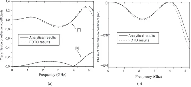
of the sheets. Equation (26) is introduced in Eqs. (18)-(19). In Fig. 7(a), are plotted the amplitude of the transmission and reflection coefficients and in Fig. 7(b) is plotted the phase of the transmission coefficient. In the same Figures, the FDTD results are also added. These curves show that the numerical and analytical calculations yield the same results. We have also validated the analytical results for other values of d (not shown here). From this, we can conclude that our theory is validated.
If the mesh ∆ tends to zero, i.e. if the space between the sheet and the interface tends to zero, then δ tends to zero and the LHM slab becomes perfectly matched to air.
0 1 2 3 4 5 −π/4 0 −π/8 P h a s e o f tr a n s mis s io n c o e ff ic ie n t (r a d ) Analytical results FDTD results Frequency (Ghz) 0 1 2 3 4 5 0,0 0,2 0,4 0,6 0,8 1,0 1,2 1,4 |R| |T| T ra n s mis s io n o r re fle c tio n c o e ff ic ie n ts Frequency (GHz) Analytical results FDTD results (a) (b)
Figure 7: Comparison between analytical and FDTD results for the characteristics of the LHM slab with matching sheets vs. frequency, for d = 40 mm and ∆ = 5mm: (a) amplitudes of the transmission and reflection coefficients, T and R (b) phase of the transmission coefficient
8. CONCLUSION
In this work, a new theory on the characteristic impedance of media with simultaneously negative permittivity and permeability, called left-handed media (LHMs), has been proposed. This theory shows that the characteristic impedance, as it is usually defined, is negative for these media. An interpretation of this result has been proposed and it has been explained why one can encounter difficulties when one considers a homogeneous LHM. Another result of our analysis is that only the non-homogeneousness is a required condition for the existence of a passive LHM and not the frequency-dispersive property which can be a consequence of the inhomogeneousness. In other words, there is a limit in the homogenization of a periodic structure, and this limit should be clearly understand to avoid misconception and surprising results. A method has been proposed to match, for forward waves, an LHM slab to free space, by using sheets of resistors and amplifiers. We have also considered the effect of an imperfectly matching. The transmission and reflection characteristics of an imperfectly matched LHM slab has been calculated by using analytical methods (transmission line and multiple-reflections methods). The proposed scheme allows to excite the forward waves of the LHM instead of the backward waves.
The numerical results presented in this paper can be tested easily by researchers active in the electromagnetic domain, without developing new numerical methods.
Future work will concentrate on the analysis of the excitation by plane wave at oblique incidence of an LHM slab and on the flat lens, by using the proposed scheme. We will also verify our theory with artificial LHMs made with periodic structures.
ACKNOWLEDGMENT
The authors gratefully acknowledge the support of this research from National Science Engineer-ing Research Council of Canada (NSERC). The authors wish also to thank Dr. Claude Kondo Assi, Prof. Christophe Caloz, and Prof. Giuseppe Conciauro, for helpful discussions or comments concerning the negative characteristic impedance.
REFERENCES
1. Veselago, V. G., “The electrodynamics of substance with simultaneous negative values of ε and µ,” Soc. Phys. Usp. , Vol. 10, No. 4, 509–514, 1968.
2. Pendry, J. B., “Negative refraction makes a perfect lens,” Phys. Rev. Lett. , Vol. 85, No. 18, 3966-3969, 2000.
3. Shelby, R. A., D. R. Smith, and S. Schultz, “Experimental verification of a negative index of refraction,” Science, Vol. 292, No. 5514, 77–79, 2001.
4. Chen, H., L. Ran, J. Huangfu, X. Zhang, and K. Chen,“Left-handed materials composed of S-shaped resonators,” Phys. Rev. E , Vol. 70, 057605-1–057605-4, 2004.
5. Parazzoli, C. G., R. B. Greegor, L. Li, and M. H. Tanielian, “Experimental verification and simulation of negative index of refraction using Snell’s law,” Phys. Rev. E , Vol. 90, 107401, 2003.
6. Houck, A. A., J. B. Brock, and I. L. Chuang, “Experimental observations of left-handed material that obeys Snell’s law,” Phys. Rev. E , 90, 137401, 2003.
7. Hooft, G. W.’t, “Comment on ’Negative refraction makes a perfect lens’,” Phys. Rev. Lett., Vol. 87, 249701-1, 2001.
8. Garcia, N., and M. Nieto-Vesperinas, “Left-handed materials do not make a perfect lens,”
Phys. Rev. Lett., Vol. 88, 207403, 2002.
9. Maystre, D., and S. Enoch, “Perfect lenses made with left-handed materials: Alice’s mirror?,”
J. Opt. Soc., Vol. 21, No. 1, 122–131, 2004.
10. Chew, W. C., “Some reflections on double negative materials,” Progress in Electromagnetic
Research, Vol. 51, No. 1, 1–26, 2005.
11. Berenger, J. P., “Three-dimensional perfectly matched layer for the absorption of electromag-netic waves,” J. Comput. Phys. , Vol. 127, No. 0181, 363–379, 1996.
12. Hwang, K. P., and A. C. Cangellaris, “Effetive permittivities for second-order accurate FDTD equations at Dielectrics interfaces,” IEEE Micr. Wir. Comp. Lett., Vol. 11, No. 4, 158–160, 2001.
13. Einstein, A., “Zur Elektrodynamik bewegter K¨orper,” Annalen der Physik , Vol. 17, 891–922, 1905.