OATAO is an open access repository that collects the work of Toulouse
researchers and makes it freely available over the web where possible
Any correspondence concerning this service should be sent
to the repository administrator:
[email protected]
This is an author’s version published in:
http://oatao.univ-toulouse.fr/23376
To cite this version:
Hilaire, Alexandra
and Andrieu, Eric
and Wu, Xinhua High-temperature
mechanical properties of alloy 718 produced by laser powder bed fusion with
different processing parameters. (2019) Additive Manufacturing, 26. 147-160.
ISSN 2214-8604
High-temperature mechanical properties of alloy 718 produced by laser
powder bed fusion with different processing parameters
Alexandra Hilaire
a,
*
, Eric Andrieu
a, Xinhua Wu
b"CIRIMAT, Université de Toulowe, CNRS, INP- ENSIACET 4 allée Emile Monso -BP44362, 31030 Toulowe Cedex 4, France b Department of Materials Science and Engineering, Mona,h University, Wellington Road, Clayton, Melbourne, Victoria 3800, Awtra/ia
ARTICLE INFO ABSTRACT
Keywords:
Laser powder bed fusion
Alloy 718
Processing parameters
High-temperature tensile properties Defects
The laser powder bed fusion (LPBF) process produces complex microstructures and specific defects. To build structural components with an acceptable mechanical integrity, optimization of the processing parameters is required. In addition, the evolution of defects under service conditions should be investigated. In this study, the nickel-based alloy 718 was studied in the as-built metallurgical state. Laser processing parameters such as the laser power, scanning speed, and hatch spacing were modified to evaluate their effects on the porosity, mi crostructure, and mechanical properties at high temperatures. The porosity and pore shape were evaluated using relative density measurements and image analysis. Moreover, the effects of the microstructure and defects on the tensile properties and damaging processes at 650 °C were investigated in air. The results revealed that the loading direction is critical to the mechanical integrity of the alloy, due to the specific orientation of the mi crostructural interfaces and defects. In addition, from observations of the fracture surfaces, inter-dendritic phases were found to act as crack initiation sites. A tensile test was conducted in vacuum at 650 °C and 2.10-4s-1, and the results indicated that damage processes were not affected by oxidation when the experi ments were carried out in air.
1. Introduction
Alloy 718 is a wrought or cast nickel-based superalloy that was developed by Eiselstein in the 1950s for Huntington Alloys. This alloy is widely used in the aircraft, nuclear, and petrochemical industries [1] because it can withstand temperatures of up to 650-700 °C keeping high strength, good ductility, and excellent stress rupture properties. These properties are mainly due to the precipitation of the strength ening phases y', and primarily y' ' [2]. Moreover, its high chromium content results in good corrosion and oxidation resistances at high temperatures. However, several studies revealed that alloy 718 is sen sitive to stress corrosion cracking under various service conditions [3,4]. Garat et al. [5] explored the effect of oxidation on the mechanical behavior of alloy 718 at temperatures ranging from 450 °C to 700 °C, and at under tensile strain rates ranging from 10-5 to 10-3 s-1• Under laboratory air testing conditions, a change in the rupture mode from fully ductile when serrated flow occurred to partially ductile with brittle intergranular areas in the dynamic strain ageing regime was observed. Therefore, depending on temperature, strain rate, and en vironmental conditions, intergranular crack initiation and propagation may occur, which leads to a decrease in the elongation to failure [6].
• Corresponding author.
E-mail address: [email protected] (A. Hilaire).
Pancou et al. [7] recently demonstrated that alloy 718 produced by additive manufacturing is also sensitive to this phenomenon.
Additive manufacturing includes ail processes that involve the layer-by-layer fabrication of near net-shape parts. Laser powder bed fusion (LPBF) is the process used in this study, and it is also referred to as laser beam melting (LBM), selective laser melting (SLM), or direct metal laser sintering or melting (DMLS/DMLM). Metallic powder par ticles are melted by an ytterbium fiber laser that scans the surface of a powder bed using galvanometer mirrors, to consolidate one slice of the metal component. The powder bed is then reconstituted with a thin powder layer and melted again to build the final component in the desired shape, layer-by-layer. Specific microstructures are therefore generated with complex phase transformations, residual stresses, and different types of defects.
A wide range of processing parameters, i.e., the powder choice, melting environment, design strategy, and laser parameters are in volved in the LPBF process. The choice of the powder with respect to its composition, morphology, size distribution, and flow characteristics is critical, as it is preferable to obtain a uniform powder bed and to reduce the formation of defects such as pores or cracks [8]. Moreover, the powder layer thickness should be appropriately set as a fonction of the
powder size and melt-pool size, to assure a high alloy density. Never theless, the melt-pool size is mainly dependent on the laser parameters [9]. An appropriate laser power, scanning speed, and hatch spacing enable the production of dense alloys [10,11] with suitable micro structures and mechanical properties [12]. Moreover, a change in the scanning strategy affects the level of residual stresses and the grain texture [13-15].
The as-built microstructure of alloy 718 fabricated by LPBF is composed of overlapping melt-pools. The solidification of the melt pools results in the formation of dendrites oriented along the thermal gradient, with widths ranging from 200 nm to 1 µm. Moreover, small inter-dendritic Laves phases and primary carbides were observed by most of the researchers [16-18]. Each group of dendrites forms grains that are elongated along the building direction.
Post-processing heat-treatments are then required to obtain suitable mechanical properties under service conditions. Prior to the ageing heat-treatment that leads to the precipitation of strengthening phases' and y'', the alloy 718 is typically stress relieved, homogenized, and/or annealed. Depending on the heat-treatment temperature, the Laves phases are partially or fully dissolved. In addition, carbides and o phases may precipitate at grain boundaries or dendrite boundaries when the homogenization of the alloy is not fully realized [17,19]. Grains remain elongated in the building direction, except when hot isostatic pressing (HIP) is carried out after LPBF to close the internai defects. In this case, the microstructure is recrystallized with large equiaxed grains and annealing twins [16,20,21]. Moreover, defects that are connected to the surface remain open. An attempt was made by Aydini:iz et al. [20] to close the surface defects using cathodic arc de position (Arc-PVD) prior to HIP.
In the literature, the mechanical properties of alloy 718 were mainly reported for the as-built state and heat-treated condition at room temperature. Nevertheless, few authors evaluated the mechanical be havior under service conditions, namely, at high temperatures such as 650 °C. With respect to the behavior at room temperature, heat-treated alloy 718 produced by LPBF exhibits tensile and low cycle fatigue (LCF) properties similar to that of the wrought alloy [17,21,22]. However, discrepancies in the properties were observed, and they can be ex plained by their high relation with the processing parameters, defects, and heat-treatments. For example, after the improvement of the LPBF alloy ductility by HIP, microstructural evolutions induced by HIP were found to reduce the LCF life of alloy 718, although an increase in the ductility was expected due to the decrease in the amount of defects
[20,21]. In addition, most of the researchers reported anisotropie ten sile properties, characterized by different yield strengths and elonga tions to failure, which were dependent on the loading direction
[19,22-25].
With respect to the mechanical properties at high temperatures, the creep and tensile behavior was evaluated by Kuo et al. [25,26] at 650 °C for various metallurgical states. The LPBF alloy in comparison with the wrought alloy exhibits a low creep rupture life and a low ductility. Moreover, significant differences in the mechanical properties were observed between the horizontal and vertical specimens. This behavior was explained by the o phase morphology and its precipitation along the columnar grain and dendrite boundaries. In addition, Trosch et al. [23] and Pancou et al. [7] observed a significant decrease in the duc tility when loading in the horizontal direction at 650 °C. This confirms the occurrence of oxidation-assisted intergranular cracking at the same temperature and strain rate conditions as that in the case of rolled 718. Therefore, according to Pancou et al. [7], microstructural parameters are not the major controlling factors leading the oxidation-assisted in tergranular cracking.
The production of near net shape nickel-based alloy structural ele ments with a good mechanical integrity and cracking resistance under service conditions has attracted significant research attention. In metal additive manufacturing processes, reduction of the processing steps that lead to the final product is a major objective that can be reached by
optimizing the choice of building parameters and topological design. However, the zero-defect target has not been realized. Consequently, the defects generated by the process require characterization, to assess their potential effects on crack initiation. In this study, alloy 718 was evaluated under the as-built condition. This was under the assumption that if the defects degrade the mechanical properties in as-built me tallurgical state, structural strengthening heat-treatments would only increase the cracking sensitivity. Therefore, the first step of this study was the evaluation of the types of defects that occur in as-built alloy 718 as a function of the laser processing parameters. The primary focus was on the effects of the laser power (P), laser scanning speed (S), and hatch spacing (HS) on the defect types. Tensile tests at 650 °C were carried out to evaluate the effect of the LPBF defects on the mechanical integrity of alloy 718. Moreover, the defect geometry, microstructure, loading mode, and environmental effects were evaluated. The final aim was to identify the type of defects and/or microstructural elements that can lead to the premature damage of the alloy, to reduce their impact using an optimized post-processing heat treatment.
2. Materials and methods 2.1. Material processing route
All the samples were fabricated by LPBF with 718 gas-atomized powder supplied by Carpenter Powder Products (Carpenter Powder Products Inc, Bridgeville, USA). Laser powder bed fusion was carried out at the Monash Centre for Additive Manufacturing (Australia) using two EOS machines: EOS-M280 and EOS-M290 (EOS GmbH Electro Optical Systems, Krailling, Germany). The machines were equipped with a 400 W Ytterbium fiber laser with a wavelength ranging from 1060 to 1100 nm, and a laser beam diameter of 100 µm. The fabrication was carried out in an argon atmosphere with an oxygen level below 0.1 %, to prevent oxidation. The laser scanning strategy followed a stripe pattern with a rotation angle between two successive layers. The samples were fabricated without contour parameters, to accurately measure the melt-pool depth of the last layer, with the exception of parameter set A. The powder layer thickness was fixed at 40 µm, whereas the laser power (P), scanning speed (S), and hatch spacing (HS)
were modified. These processing parameters are expressed by their ratios with respect to a reference value, namely, P1, Smax, and HSmax,
respectively. Each parameter set can be related to an energy density dE, to represent the surface energy applied to the metal. Different formulas were found in the literature to express the laser energy density using the laser parameter, scanning speed, hatch spacing, or layer thickness [10,11,27,28]. In this paper, the energy density is expressed by dividing the laser power (P) (unit: W) by the scanning speed (S) (unit: mm.s-1) and hatch spacing (HS) (unit: mm):
dE = P/(S X HS) (1)
However, it should be noted that due to the reflectivity of the ma terial surface, the effective energy transmitted to the material is not directly proportional to the beam energy. High laser powers were in vestigated to minimize the building time, and the energy density was varied between 1.2J.mm-2 and 4.8J.mm-2 to evaluate the geometry and location of the defects in the LPBF alloy.
2.2. Powder granulometry and chemical composition
A laser diffraction particle size analyzer was used to determine the powder size distribution. The powder and alloy chemical compositions were measured by EAG (Evans Analytical Group SAS, Tournefeuille, France) using inductively coupled plasma optical emission spectroscopy (ICP-OES) for the high-content alloying elements, glow discharge mass spectrometry (GDMS) for the low-content alloying elements, and in strumental gas analysis (IGA) for the gas-forming elements.
2.3. Porosity investigations
Samples with dimensions 12 mm x 9 mm x 9 mm were fabricated to investigate the effect of the processing parameters on the porosity. The densities of all the samples were measured using Archimedes' method [29]. The samples were weighed four times in air and in dis tilled water. The relative densities were then obtained by comparison with the density of a wrought 718 sample, which was assumed to be fully dense. The uncertainty of the measurement was estimated as 0.2%.
To investigate the sizes, shapes, and the localization of the pores, an image analysis of the vertical cross-section was conducted. The samples were first eut in the vertical direction, mounted, ground, and then po lished with an alumina finish using an automatic polishing machine. The vertical cross-sections were observed using a MA200 Nikon optical microscope (Nikon France SAS, Champigny-sur-Marne Cedex, France). A minimum of 50 images, which represent an area of 1 cm2, were captured for the entire cross-section and analyzed using ImageJ• soft ware. The porosity was calculated based on an appropriate threshold. Moreover, only the pores with diameters larger than 1 µm were ana lyzed. The shapes of the pores were determined by calculating their circularity using the following formula:
circularity = 41ra/ p2 (2)
where a and p are the area and the perimeter of the pores, respectively. The pores were assumed to be spherical when the circularity was above 0.9.
2.4. Microstructural characterization
The microstructure was investigated to determine the metallurgical state involved in the mechanical behavior of the material during the tensile tests. The microstructures of the as-built samples were revealed by etching with a 10% oxalic acid solution at 5 V for approximately 5 s, or using Kalling's n°2 reagent for approximately 40 s.
The melt-pool size of the final layer was characterized for various processing parameters. Prior to the observation, the samples were eut perpendicular to the last laser tracks, to maintain the same observation conditions for each sample. They were then observed using an optical microscope, and measured using ImageJ" software. The average depths and widths of the melt-pools were measured for 40 melt-pools of each sample. The widths of the melt-pools were measured at the top and at 40 µm from the bottom of each melt-pool, to ensure consistency with the layer powder thickness of 40 µm.
The dendritic microstructure was observed on the etched samples using a secondary electron detector of a LEO435VP scanning electron microscope (SEM) (Carl Zeiss France SAS, Marly-le-Roi, France) or on the polished samples with alumina finish using a backscattered electron detector. The inter-dendritic precipitates were examined using a JEOL JSM-7800 F Prime FEG-SEM (JEOL Europe SAS, Croissy-sur-Seine, France) with an accelerating voltage of 5 kV. Their identification was performed at 200 kV using a JEOL JEM 2100 F transmission electron microscope (TEM) equipped with SDD Bruker energy dispersive x-ray spectrometry (EDS) (Brucker France SAS, Palaiseau, France).
2.5. Mechanical integrity investigation
Large blocks (80 mm x 15 mm x 70 mm) with five selected proces sing parameters were built to machine the fiat tensile test samples in three directions (Fig. 1). Moreover, the processing parameters were selected such that only one parameter, i.e., P, S, or HS was changed for each process. Furthermore, they are defined in Table 1 and denoted by the letters A, B, C, D, and E.
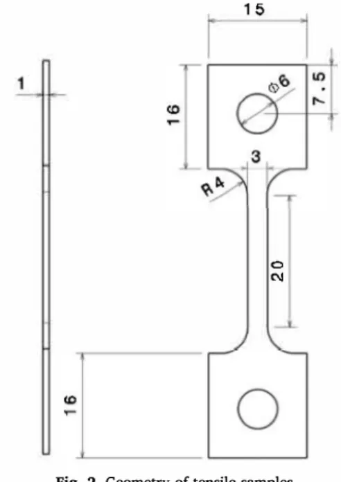
Tensile test samples were fabricated using an electro-sparking ma chining in accordance with the geometry presented in Fig. 2. There after, they were ground using SiC papers (180-2400 grit), to remove the
Fig. 1. Sampling of tensile samples in a large block.
Table 1
Processing parameters of samples used for melt-pool size characterization and tensile tests. Processing parameters A A B C D E (core) (upskin') P/P1 0.9 0.5 1.2 1.0 1.0 1.2 S/Smax 0.4 0.3 0.6 0.6 0.6 0.8 HS/HSmax 1.0 0.8 1.0 1.0 0.5 1.0 dE (J.mm-2) 2.7 2.8 2.7 2.2 4.8 1.9
* These processing parameters were used only for the final layer of sample A. 15
0 C\l
Fig. 2. Geometry of tensile samples.
heat-affected zone. Tensile tests were conducted on the as-built fiat specimens at 650 °C in air, with a strain rate of 10-4 s-1 using an MTS Criterion Model 43 equipped with a three-zone resistance furnace (MTS Systems SAS, Créteil Cedex, France). The tensile samples were then heated at 30 °C.min -i up to 650 °C, which allowed for the precipitation of prior to the tensile test. The strain was measured using a high temperature contact extensometer with a gauge length of 18 mm. To determine a possible effect of the environment on the mechanical in tegrity, tensile tests were also conducted in vacuum using an MTS
15 100 , , , 90
i
, , 12 80 '; 70 ,§ 9 60'§
- 50 -� "C·
.:
6 - 40 �-�
,,:::: Q - 30 o= 3 20 10a
0 50 100 150 Partide size (pm)Fig. 3. Particle size distribution of the 718 powder.
Synergie 1000 (MTS Systems SAS, Créteil Cedex, France) equipped with a three-zone halogen lamp furnace, laser extensometer, and vacuum system. The fracture surface and gauge length were then observed using a FEI Quanta450 scanning electron microscope (FEI France SAS, Vil lebon-sur-Yvette, France).
3. Results and discussion
3.1. Powder and chemical composition
The morphology of the powder was found to be mainly spherical with a mass median diameter of approximately 40 µm (Fig. 3). Several gas pores and satellites were observed within the powder particles, as illustrated in Fig. 4. The chemical composition of the as-built alloy fabricated with parameter set A was compared with that of the powder. The results presented in Table 2 reveal that the powder and as-built alloy had similar chemical compositions. In particular, no differences were observed with respect to the aluminum and manganese contents, despite the low boiling points, low vaporization heats, and high vapor pressures of these elements. However, the powder exhibited a higher oxygen and hydrogen content than that of the as-built alloys. This may be due to the contribution of the adsorbed water vapor during the storage of the powder over a long period of time.
3.2. Microstructure and defects in as-built alloy 718
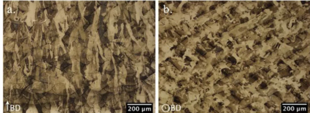
The microstructural characterization revealed that the LPBF process generates microstructures of different size scales. In Fig. Sa, the su perposition of the melt-pools on the section parallel to the building direction (BD) was observed, which confirms the layer-by-layer fabri cation process. The melt-pool width was hundreds of micrometers,
Fig. 4. Optical micrographs of 718 powder particles.
depending on the processing parameters. In Fig. Sb, laser tracks in ac cordance with the scanning pattern were observed on the section per pendicular to the building direction. The width of these tracks was equivalent to the chosen hatch spacing, and the angle between two tracks corresponds to the pattern rotation angle between two successive layers. Moreover, Fig. 5 reveals the anisotropie grain morphology. As expected, due to the thermal gradient, grains were elongated in the building direction, whereas several equiaxed grains were observed in the section perpendicular to the building direction.
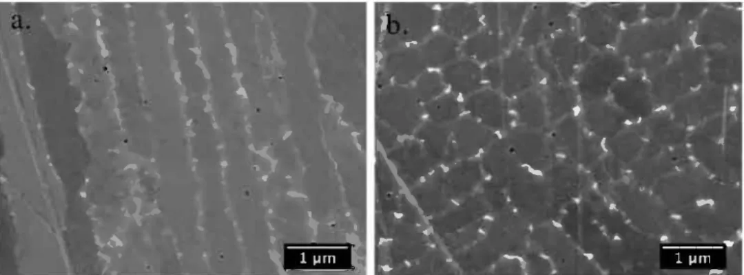
Each grain is formed by a stack of parallel dendrites. Figs. 6 and 7 present the columnar-dendritic solidification structure of the alloy 718 within the grains. The dendrites had widths Jess than 1 µm, and were oriented across the upper center of the melt-pool, due to the thermal gradient during melt-pool solidification. Moreover, as reported by Shifeng et al. [30] and Tomus et al. [31], epitaxial dendritic growth was observed through the layer-layer melt-pool boundaries, and a change in the dendrite direction was observed between the track to track melt pool boundaries. Therefore, when epitaxial growth occurred, the melt pool boundary was underlined by the swelling of the dendrites along 5 µm. This may be due to the modification of the local heat transfer at the bottom of the melt-pool during the solidification process, which led to a decrease in the cooling rate and an increase in the dendrite arm spacing (Fig. 7). The inter-dendritic phase precipitation was therefore enhanced in this region.
Fig. 8 presents the inter-dendritic phases with sizes ranging from tens of nanometers to 400 nm. These phases were identified as Laves phases of the NbCr2 type, and as primary carbides of the NbC type, as presented in the TEM diffraction patterns in Figs. 9 and 10, respec tively; in conjunction with the EDS analysis results. Table 3 presents the chemical compositions of the Laves phases and primary carbides, which are in good agreement with the literature [32-34]. The dendrite trunk was depleted in Nb, Si, Ti, and Mo, given that the partition coefficient of these elements are less than unity [33]. Therefore, there was an en richment of Nb, Si, Ti, and Mo in the inter-dendritic liquid during so lidification, which resulted in the precipitation of primary carbides (Nb,Ti)C and Laves phases (Nb, Mo, Ni, Si)(Fe, Cr, Ti)2 by an eutectic reaction in the inter-dendritic region [35]. Moreover, no sub-structure spots related to the strengthening precipitates were observed in the diffraction patterns.
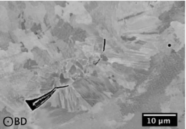
The as-built 718 metallurgical state is also characterized by the occurrence of specific defects. Spherical gas pores with diameters of several micrometers were observed in close proximity to the melt-pool boundaries, as seen in Figs. 6 and 13. It is probable that they originated from the gas trapped inside the powder particles during the gas ato mization [36] and the gas trapped between the powder particles during the laser melting. Nanometric pores were also observed in the inter dendritic regions, as shown in Fig. 8. They were formed from the gas enrichment of the liquid during the solidification process. Figs. 11 and 12 display other pores with irregular shapes, which indicate a lack of fusion. This pore type is due to insufficient melting, resulting from very small overlaps between adjacent or bottom-layer melt-pools. The mi crostructure in close proximity to this type of defect is typical of par tially un-melted powder, as shown in Fig. 12, where similar micro structures were observed for the un-melted powder particle attached to the sample edge and in close proximity to the irregular cavities. Fig. 13 presents intergranular and/or inter-dendritic cracks with origins that can be explained by the high thermal stresses induced by the process, in addition to the inter-dendritic segregations that can induce liquation cracking in the heat-affected zone. The nature and the amount of these defects can be modified by applying different processing parameters. 3.3. Effect of processing parameters on the relative density of alloy 718
The relative density is presented in Fig. 14. Ail the samples were more than 97% dense. The relative densities of the samples initially increased in accordance with an increase in the energy density, then the
Table 2
Chemical composition of the 718 powder and the as-built alloy (unit: wt. %).
Elements Ni Cr Fe Nb Mo Ti Al Powder 53.5 19.7 16.4 5.06 3.11 0.95 0.688 ± 0.7 ± 0.2 ± 0.2 ± 0.05 ± 0.02 ± 0.01 ± 0.008 As-built alloy 53.9 19.7 16.5 5.09 3.21 0.96 0.692 ± 0.4 ± 0.5 ± 0.1 ± 0.10 ± 0.03 ± 0.01 ± 0.009 Elements Co
w
Si Mn p Cu Powder 0.32 0.16 0.044 0.014 0.005 0.0030 ± 0.1 ± 0.05 ± 0.009 ± 0.003 ± 0.001 ± 0.0006 As-built alloy 0.32 0.19 0.038 0.013 0.004 0.0028 ± 0.1 ± 0.05 ± 0.008 ± 0.003 ± 0.001 ± 0.0006 Elements Bs
Powder 0.0018 0.0026 ± 0.0004 ± 0.0005 As-built alloy 0.0014 0.0023 ± 0.0003 ± 0.0005values were constant at 99.6% from 1.8 J.mm -2, which is consistent with the results obtained by Wang et al. [10]. The variations observed at higher energy densities may be explained by the high uncertainty of the measurements. Nevertheless, the lower hatch spacing resulted in denser samples, which is consistent with an improved overlap between melt-pools. Moreover, a higher density was reached with the same scanning speed by increasing the laser power, as shown in Fig. 15. However, the increase in the power at a low scanning speed resulted in a slight decrease in the relative density, which could be indicative of keyhole formation [37]. This trend was not clearly observed in Fig. 14; however, a decrease in the relative density was expected at an energy density higher than 5 J.mm -2•
Relative density measurements therefore provide a processing window to minimize the time required for the production of dense parts. However, no information on the size, spatial distribution, and morphology of the defects is available. Consequently, image analysis was conducted to accurately characterize the size, morphology, the surface fraction of the defects.
3. 4. Effect of processing parameters on the porosity and on the shape of pores
Fig. 16 presents the evolution of the porosity as a function of the energy density using the same hatch spacing and two different laser powers. An increase in the energy density for a given laser power was therefore equivalent to a decrease in the scanning speed. The image analysis results confirmed that the porosity decreased significantly at low energy densities (continuous lines). Moreover, an increase in the laser power increased the porosity at low energy densities due to the higher scanning speed, which generated more defects. Nevertheless, for
0 C N H
0.023 0.073 0.021 0.0009
± 0.002 ± 0.002 ± 0.002 ± 0.0001 0.011 0.068 0.023 0.00019
± 0.001 ± 0.002 ± 0.002 ± 0.00002
Fig. 6. Optical micrographs of dendritic growth through melt-pools and sphe rical pores.
the same scanning speed, the porosity decreased when the laser power increased. Two types of pores were observed: irregular pores and spherical pores. Irregular pores can be removed using high energy densities, whereas spherical pores are present regardless of the pro cessing parameters used. In this study, the spherical porosity was below 0.1 %, and decreased slowly in accordance with an increase in the en ergy density. At high energy densities, the pores were mainly spherical, whereas the irregular porosity increased when the energy density de creased. The apparent optimal parameters correspond to the highest energy density. Nevertheless, Fig. 17 reveals that large spherical pores with diameters of 80 µm exist at high energy densities, whereas the
Fig. 7. SEM image of dendrites through a melt-pool boundary. mean diameter is approximately 5 µm.
3.5. Effect of processing parameters on the microstructure of as-built alloy 718
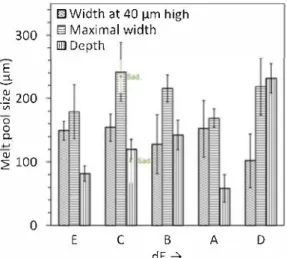
As previously discussed, irregular pores can be avoided by using a suitable set of processing parameters that result in sufficient overlap between the melt-pools. Figs. 18 and 19 reveal the effects of the hatch spacing, laser power, and scanning speed on the morphology of the melt-pools for energy densities higher than 1.8 J.mm-2• First, a com parison of the melt-pool shapes between processing parameters A and B revealed that an equivalent energy density does not result in the same melt-pool shapes. An increase in the power and scanning speed of parameter B resulted in wider and deeper melt-pools than those of parameter A. Nevertheless, the width at a height of 40 µm was lower for parameter B. For the same hatch spacing and scanning speed, an in crease in the laser power (from parameters C to B) resulted in deeper and slightly narrower melt-pools. However, the same ratio was ob tained between the maximal width and the width measured at a height of 40 µm. According to Sadowski et al. [9], an increase in the laser power increases the depth and width of the melt-pools. Nevertheless, the authors observed a stabilization of the width at a high laser power for several scanning speeds. Processing parameters C and B were in the stabilization region, and the values obtained for parameter C were in agreement with the results obtained by Sadowski, as seen in Fig. 19. With respect to the laser scanning speed, the melt-pool depth and maximal width increased when the scanning speed decreased (from parameters E to B), whereas the width at a height of 40 µm decreased. It
"" r....
"\.
'
'
...
1\•
...
..
'
•
\�
l,
,
,!
•.•
..
'
...
1
,._
\
'î
'
.
\
4\·\
t.1.
r.
,
.
·"
'\
,
\ 1 ..i'"
t
�
..
\
1·.
•
•
\
'
'...
�
.
;,�
.
'
�-. ,,
.4,.:.
\,�·
0,,_
;
W9 1•
•
..
'(" \ ,}.
..
·,•
.
·
-
.
'
.
�
\�
'
-
.
.
,
�
,
is therefore evident that an increase in the energy density energy due to changes in the laser power or scanning speed promote a significant evolution of the melt-pool shape. However, the melt-pool shape is also influenced by the hatch spacing. The melt-pool depth was doubled by a significant decrease in the hatch spacing (from parameters C to D). Moreover, it should be noted that the defects in sample E modified the melt-pool shape by changing the thermal gradient (Fig. 18). Similarly, when a surface roughness is created after the melting, the melt-pools of the following layer do not possess the same shape, due to the difference in thermal conductivities between the solid alloy and powder. Fur thermore, the shapes of the melt-pools were not similar to the shapes that were observed in the laser keyhole-mode by King et al. [38]. Therefore, the increase in the gas pore size at high energy densities is not related to this effect under these conditions, except if gas pores are localized in close proximity to the edges where the powder bed locally modifies heat transfers.
3. 6. Effect of mechanical loading direction on the mechanical properties at
6so·c
Tensile samples were machined in three directions in the blocks. Due to the microstructural anisotropy associated with grain mor phology and melt-pool shape, the mechanical behavior was expected to be anisotropie as a fonction of the sample direction, as shown in Fig. 20. The loading direction was parallel to the building direction for the VY tensile sample, whereas it was perpendicular to the building direction for HY and HZ samples. The stress level applied to the layer-layer melt pool boundaries was therefore high for the VY sample. Moreover, in the case of the HY and HZ samples, the track to track melt-pool boundaries were the most stressed interfaces. In addition, with respect to the grain shape elongated in the building direction, longitudinal loading corre sponds to the VY sample, whereas transverse loading corresponds to the HY and HZ samples.
Fig. 21 presents the tensile behavior of the as-built alloy 718 for the different loading directions at 650 °C and a strain rate of 10-4 s-1• The vertical sample exhibited a larger elongation and smaller tensile strength than the horizontal samples. This anisotropy was also observed in the literature for as-built and heat-treated nickel-based alloys at room temperature and high temperatures [16,19,22,23,39]. Deng et al. [24] explained that this mechanical anisotropy is mainly induced by a different residual stresses and dislocations accumulated in the as-built horizontal and vertical samples. Nevertheless, the grains morphology is also a critical factor, and the presence of elongated grains along the building direction can explain the mechanical behavior. Moreover, more grains boundaries are present to disrupt the motion of dislocations when the loading is horizontal to the building direction.
For comparison, a solid solution 718 rolled sheet was also tested under the same mechanical testing conditions. Fig. 21 reveals that the yield strength of as-built alloy 718 (629 MPa) is significantly higher
i
-
�
-
-{'
�
.-
�
t
A..,
-
'
.,..
'.'
'
-
.
'
..,
...
\
>
_
.,
(.�
....
'
,.
"••
...
'
'
"'
·
...
•.. ..
.. 1....
.
..
,-"
----
--..
--.
...
1 µrn...
-:
�
Fig. 8. FEG-SEM images of Laves phases and nanometric pores in the inter-dendritic regions: dendrites in directions (a) parallel and (b) orthogonal to the primary arm.
Fig. 9. (a) TEM bright field image and (b) diffraction pattern of Laves phase in as-built alloy 718.
liiM11i
Fig. 10. (a) TEM bright field image and (b) diffraction pattern of NbC in as-built alloy 718. Table 3
Chemical composition (wt. %) of inter-dendritic precipitates and dendrite trunk measured using TEM-EDS.
Elements Ni Cr Fe Nb Mo Ti Al Si Dendrite trunk 54.7 19.7 17.3 4.1 2.8 0.7 0.5 0.2 Laves phases 41.7 14.7 11.1 25.7 4.8 1.2 0.5 0.6 Laves phases [33] 45.8 13.3 11.6 22.3 4.6 1.2 1.4 NbC 4.7 6.8 1.4 69.6 6.8 9.4 0.2 1.2 NbC [33] 4.7 2.5 1.5 80.4 2.5 8.4 0.0
than that of the solution annealed rolled sheet (392 MPa). The high as built strength can be explained by the fine dendritic microstructure and the inter-dendritic precipitation of the Laves phases and carbides. In addition, the elongation of the as-built alloy 718 was lower in the horizontal and vertical directions than that of the solution annealed sheet; however, they both reached similar ultimate tensile strengths. The as-built alloy therefore reached the ultimate tensile stress that precedes damage in a shorter time than the solid solution rolled alloy. Similarly, Aydinèiz et al. [20] considered that the high strength and the low ductility of the as-built 718 are due to ill-defined boundaries formed by the Laves phase precipitates and sub-micron sized cell structures.
It should be noted that the tensile curves for HY, VY, and the rolled sheet exhibited a serrated shape which is indicative of plastic in stabilities known as the Portevin-Le Chatelier (PLC) effect. This is
0BD
Fig. 11. SEM image of an un-melted powder particle surrounded by lack-of fusion defects and spherical gas pores in the as-built alloy 718.
consistent with the results obtained by Max [ 40], which demonstrate the occurrence of this effect in a solid solution rolled alloy 718 below 700 'C at a strain rate of 10-4 s-1; in addition to the results obtained by Rezende et al. [ 41], who observed a serrated flow at temperatures of up to 750 'C at a strain rate of 3.2 x 10⁻⁴ s-1 for an annealed forged alloy 718. However, no serrations were observed on the HZ tensile curves, and they were only present at the early stages of the plasticity for the HY and VY tensile curves, which suggests that the limit between the
Fig. 12. SEM image of un-melted powder particles located beneath and on the top of the as-built alloy 718 surface. Lack of fusion was visible around the in ternai powder particle.
Fig. 13. Optical micrographs of intergranular cracks and gas pores in as-built alloy 718.
100%
�
ïii 99% C CIi "tJ QI.�
i
t
...
roai
98% 0::'
fi
■
HSmax ♦0.8 HSmax 97% 1.02.0
3.0 4.0 5.0dE (J/mm
2)
Fig. 14. Effect of laser energy density on the relative density of alloy 718 for two hatch spacing (HS) values.
solute dragging and the triggering of the PLC instabilities was close to 10-4 s-1 at 650 °C.
3. 7. Effect of mechanical loading direction on the fracture mode at 650 °C Fracture surfaces were observed using an SEM, to clearly determine the fracture mode of the LPBF alloy 718. For the vertical samples,
100% � 99% "iii C QI "tJ QI > ':;;
� 98%
97%
i
♦
P1
l
�
0.2
0.4
0.6
0.8
S/Smax
+
!
1.0
1.2
Fig. 15. Effect of scanning speed on the relative density for two laser power (P) values and a given hatch spacing.
0.5% �---� ---0.4% � 0.3% t': ·;;; !: 0.2% 0
c..
0.1% -+-Laser power = P 1 --Laser power= 1.2 P 1 -Total porosity rate--·Spherical porosity rate
...
----
-
...
�
=
-
--
-
-
..-
=
=
===
=
..
--0.0%
+--,----�-,----��--.---��--2 3 4
dE (.J .mm·2)
Fig. 16. Effect of energy density dE and laser power Pon the porosity and pore
morphology.
0.5% 80
•Porosity rate ax.
■Average diameter of spherical pores Ê
0.4% ..$ 60 � 0 .fl Q, <'l
..
0.3% Max...
<J ..ô Max 40"5 ·;;; 0..
-=
Q, 0.2% M u l"'
0....
� ---Ml 0 20.fl 0.1% 0, 4 4 -3'----
§i:S
0.0% 3 0 2 3 4 dE(J.mm·2)Fig. 17. Effect of energy density dE on the spherical pore size for the laser
power Pl.
Fig. 22a presents a mixed fracture mode with ductile, inter-dendritic, and inter-melt-pool fractures. These structures are similar to the laser track pattern observed on the horizontal sections. Moreover, the cross sectional observation of the vertical samples after the tensile test re vealed cracks that propagated mainly at the grain boundaries, as shown in Fig. 23a. These intergranular cracks were located at grain tip due to the relationship between the loading direction and grain orientation.
Fig. 18. Morphology of the final melt-pool in samples with heights of 9 mm fabricated with processing parameters A, B, C, D, and E (Table 1).
E
.E,
300
-� 200
"'
0 0 Q. � 1000
m
Width at 40 µm high
�
Maximal width
lllJ Depth
E C B dE➔
A DFig. 19. Dimensions of final melt-pools observed in samples with heights of 9 mm fabricated with the processing parameters presented in Table 1. Para meter C was compared with values obtained by Sadowski et al. [9]. Moreover, in some cases, they matched with the melt-pool boundaries. On the other hand, the fracture surface of the horizontal samples (Fig. 22b) were characterized by regions with inter-dendritic fractures, which were larger than those of the vertical samples. These results are consistent with the presence of elongated grains in the building
� 800 a'; 600
"'
oj)-ê
400 0) C ·gi 200JJ.l 0% -Vettical VY -Horizontal HZ -Horizontal HY-Solution annealed sheet SAS
10% 20% 30%
Engineering elongation 40% Fig. 21. Tensile curves of alloy 718 built with parameter set A obtained at
650 °C and a strain rate of 10-4 s·1 as a function of the loading directions (cf. Fig. 1).
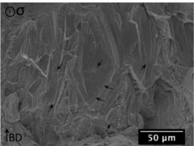
direction. Figs. 22(b) and 24 reveal several melt-pool boundaries frac tures that were in accordance with the inter-dendritic fracture by shearing. However, several undamaged melt-pool boundaries were also observed on the large inter-dendritic fracture surface, as shown in Fig. 25. This fracture mode may be related to the large intergranular cracks that propagated along the elongated grains and across several melt-pool boundaries without damaging them, as observed in Fig. 23(b). The cross-sectional observation also revealed several
d.
Fig. 20. Tensile sample volume superimposed on the microstructure at the same scale, illustrating the relative orientation between the loading direction (grey arrows) and microstructural anisotropy. The width (wd.) and the thickness (th.) of the reduced section are indicated for each tensile sample orientation.
Fig. 22. SEM images of fracture surface of (a) vertical VY and (b) and horizontal HY tensile samples fabricated with parameter set A. Fractures on melt-pool boundaries are underlined by dotted lines.
Fig. 23. Intergranular ductile cracks observed after tensile test in the bulk of the (a) VY and (b) HY tensile samples fabricated with parameter set A.
Fig. 24. Fracture at melt-pool boundaries observed on fracture surface of HY tensile sample.
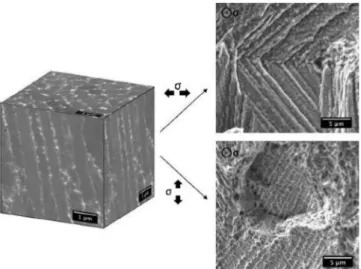
intergranular cracks, which are indicative of the inter-dendritic fracture mode. Thus, vertical and horizontal samples have two different fracture surfaces due to the microstructural anisotropy. However, in both cases, the fracture surface was mainly ductile with 1-µm wide dimples, and it contained inter-dendritic, intergranular, and inter-melt-pool fractures. Only the size and the localization of the regions varied in accordance with the microstructures observed for both sections, as shown in Fig. 5. In addition, inter-dendritic fractures exhibit a lower ductility than trans-dendritic fractures, due to the near-continuous Laves phase and carbides precipitation between the dendrites. This fracture mode, when located at a grain boundary, could also be explained by the opening and the propagation of pre-existing intergranular micro-cracks. In the case of trans-dendritic fractures, 1-µm wide dimples were formed due to the initiation of micro-voids around the inter-dendritic precipitates,
Fig. 25. SEM image of HY fracture surface displaying an inter-dendritic frac ture. Undamaged melt-pool boundaries are indicated by arrows.
followed by their deformation and coalescence in the dendrite trunk, as shown in Fig. 26.
It should be noted that inter-dendritic fractures were mostly present at the edges of the tensile samples, and that the region was slightly oxidized. The coupling between oxidation and the fracture mode identified on the aged materials may occur on the as-built material. Therefore, the tensile was conducted in vacuum, to prevent an oxygen assisted crack initiation process. As shown in Fig. 27, at the specified strain rate, the testing environment did not have a significant effect on the mechanical behavior and the elongation to fracture of the vertical samples. Moreover, serrated plastic flow was observed at the early stages of the plasticity, which indicates that the boundary between the dynamic strain aging (DSA) and PLC was close to the testing strain rate. Consequently, oxygen-assisted crack initiation and propagation could
Fig. 26. Inter-dendritic and trans-dendritic fracture surface as function of the loading direction. 1000 900
800
a..�
700
600
(1/ 500.§
400
300 'iîo200
-Vacuum 100 -Air 0 0% 10% 20% 30% Engineering elongationFig. 'Z7. Tensile test of vertical samples fabricated with parameter set A at 650 °C and strain rate of 2.1 o- 4 s·1 in air and in vacuum.
not occur, and the elongation was therefore not affected by the en vironment. However, for a lower strain rate and a higher flow stress, a decrease in the total elongation is expected under the in-air testing conditions [6]. Therefore, the inter-dendritic fracture can be mainly explained by the presence of the brittle Laves phases, which tend to lower the decohesion stress between dendrites. Depending on the dendrite orientation, the stress reaches the inter-dendritic decohesion stress, which leads to fracture initiation, or a ductile fracture develops around the inter-dendritic precipitates.
1000 Horizontal
..
a. 800�
600 t:..
.-A .§ 400 _,..El-
c
'iii, 200 --a-D"'
-+-E 03. 8. Effect of processing parwneters on the mechanical properties at 650 °C Tensile samples with degraded processing parameters were also tested to determine the effect of the defects on the mechanical integrity of the alloy 718 at 650 °C. The tensile test curves of the horizontal and vertical samples are presented in Fig. 28. It should be noted that only the processing parameter A exhibited serrated flow in the horizontal loading direction, whereas the PLC effect is observed for ail processing parameters in the vertical loading direction. Therefore, interactions between solute elements and dislocations can be modified by the pro cessing parameters and loading direction.
The mechanical properties obtained at 650 °C were plotted as a fonction of the relative density in Fig. 29. The yield strength (YS) and elongation (s D found by Kuo et al. [ 42] for the as-built alloy were equivalent to that obtained for processing parameter D, whereas the ultimate tensile strength CUTS) was close to strength obtained with processing parameter A. For relative densities higher than 99%, the yield strength and ultimate tensile strength were not related to the energy density, relative density, or melt-pool size. The morphology and size of the grains were not investigated; however, they may have an influence on the material strength. With respect to the elongation to failure, dense tensile samples exhibit a better elongation when they are stressed in the direction parallel to the building direction ( vertical). The vertical elongations obtained with the processing parameters A and D were 20% and 24%, whereas their horizontal elongations were 13% and 15%, respectively. The higher elongation obtained with processing parameter D could be explained by the lower yield stress. However, when defects are initially present in the material, the vertical elonga tion falls below 5%, regardless of the amount of defects; whereas the horizontal elongation is dependent on the rate of defects. For example, in comparison with the processing parameters A and D, samples Band C exhibited a significant drop in vertical elongation, but only a slight reduction in the horizontal elongation, despite the observation of lack of-fusion defects on the fracture surface, as shown in Fig. 30. The de fects therefore decreased the elongation of the alloy. Nevertheless, given the size of the defects, the mechanical properties were still ap propriate. However, when the scanning speed was increased sig nificantly, as in the case of the processing parameter E, the yield strength decreased by 100 MPa, and the horizontal elongation de creased up to 5.5% due to the high porosity. Large Jack-of-fusion defects were observed on fracture surface E, which explains the degradation of the mechanical properties. Therefore, when the processing parameters are slightly degraded, the defects, that are mainly created by in sufficient overlaps between the melt-pools layers, lead to a significant decrease in the vertical elongation, whereas the horizontal elongation remains appropriate. When the defects are highly distributed in the material, there is also a significant decrease in horizontal elongation.
Lack-of-fusion defects were observed on the fracture surfaces, in addition to a surrounded inter-dendritic fracture, as shown in Fig. 30. The shape of the defect therefore generated a stress concentration at the
1000 Vertical
..
8006
::1 600;
C 400 ·;:; ·;;;, C 200 w -.--E 0 0% 10% 20% 30% 0% 10% 20% 30%Engineering elongatlon Engineering elongation
6
<Il>-"'
c.. 2 :::,Yield strength
□Horizontal • Vertical 800 700600 Kuo et al. (vertical)
---500 B C D
98.5% 99.0% 99.5%
Relative density Ultimate tensile strength
□Horizontal • Vertical 1000 900 Kuoelal. (vertical) _______
f _
Î __
800 700 600 500 98.5% 30%f
f
EB C
99.0% 99.5% Relative densityStrain to failure
□Horizontal • Vertical�\JO et al. {vertical)
25% 20% D
•
wl5% □ □ □ 10% 5% □•
•
•
E B C D 0% 98.5% 99.0% 99.5% Relative densityf
f
A 100.0%.i
----t
A 100.0%•
□ 100.0% Fig. 29. Mechanical properties of horizontal and vertical as-built samples at 650 'C and strain rate of 10-4 s·1 for parameter sets A, B, C, D, and E, as shown in Table 1. Tensile properties obtained by Kuo et al. [ 42] at 650 'C of the vertical as-built 718 samples under a strain rate of 4.25 x 10-4 s·1 were plotted on the graphs.internal surface of the pores; thus, an inter-dendritic fracture was in itiated. Nevertheless, this type of fracture was only observed because the dendrite orientation was perpendicular to the loading direction. In the horizontal samples, this condition was easily reached due to the growth of dendrites in the building direction. With respect to the ver tical samples, such a condition was satisfied. This was because the formation of cavities due to the Jack of fusion modified the surrounding thermal flows, which created radial dendrites during the solidification, as observed in Fig. 11. Consequently, the spatial orientation of lack-of fusion defects and the specific dendrite orientation around them are two important parameters involved in the damaging process. They af fect the vertical ductility more severely than the horizontal ductility at a low defect density (parameter sets B and C in Fig. 29).
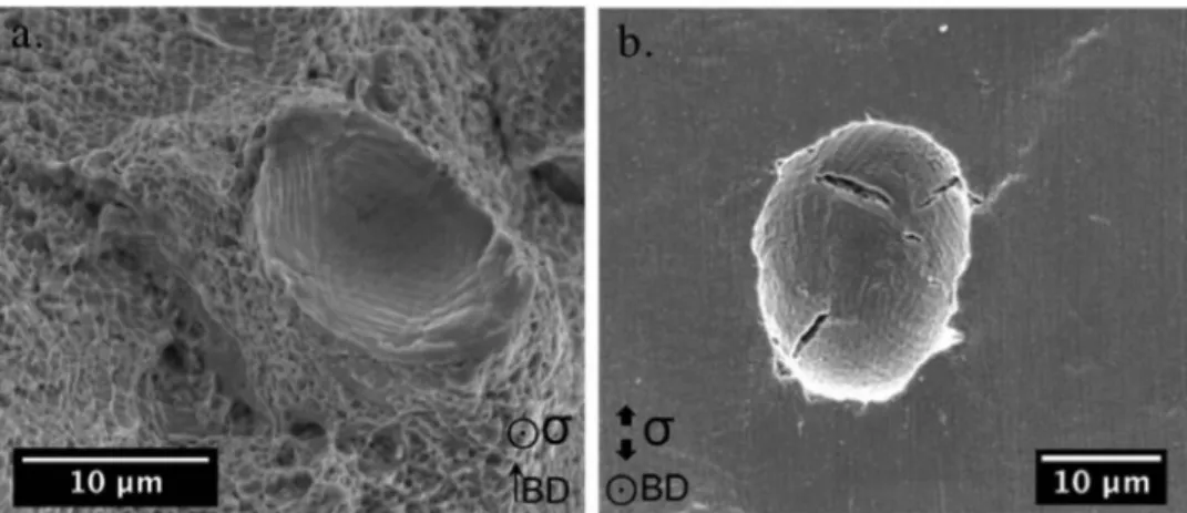
Conversely, no significant changes were observed in the micro structures around the spherical gas pores, and a complete plastic de formation with a ductile fracture was observed around such pores (Fig. 31a). At the core of the gauge length, spherical pores were only deformed in the loading direction. Nevertheless, the gauge length sur face exhibited intergranular cracks that initiated within the open pores, as shown in Fig. 31b. In addition, the presence of pre-existing cracks may also degrade the mechanical integrity of the alloy, depending on the loading direction.
4. Conclusion
Different sets of processing parameters were used in this study, to investigate their effects on the microstructural evolution alloy 718 fabricated by LPBF. Moreover, significant attention was directed to ward the defects and their effects on the mechanical integrity of the alloy, evaluated using tensile tests at 650 'C in a controlled environ ment.
The following conclusions were made:
• The modification of laser processing parameters has an influence on the type of defects and the melt-pool shape, even when the relative density is higher than 99.5%
• Fracture surfaces exhibit inter-dendritic, intergranular, and inter melt-pool fracture modes. Inter-dendritic fractures initiate the ma terial failure due to an interaction between a high stress localization and the precipitation of brittle Laves phases in the inter-dendritic spaces.
• Internai gas pores cannot be removed by optimizing the processing parameters. However, they do not initiate the fracture of the alloy under tensile loading. Conversely, surface gas pores present after machining can initiate cracks.
• The lack of fusion creates irregular-size cavities that localize and concentrate stresses. Given that they are also surrounded by speci fically orientated brittle interfaces, the initiation of sharp cracks is promoted; thus, local toughness is achieved in a short period of time.
• The loading direction in comparison with the microstructural in terfaces and defect orientation is critical to the mechanical integrity of the alloy. Although the vertical loading direction exhibits a better elongation for the defect-free alloy, the presence of Jack-of-fusion defects is more critical in this direction than in the horizontal di rection.
• No environmental effect on the as-built alloy was observed under the mechanical testing conditions.
Finally, the optimization of the processing parameters should be carried out to minimize the building time and to obtain an improved microstructure and defect orientation under the in-service local loading direction conditions of the structural element. Novel post-fabrication heat treatments that locally modify the microstructures around defects could be developed to improve the local cracking resistance of alloy 718 fabricated by LPBF.
Fig. 30. Un-melted areas observed on the fracture surface of the horizontal samples fabricated with processing parameters C (a) and E (b).
Fig. 31. (a) Ductile fracture around gas pore and (b) open gas pore observed at the surface of a tensile sample fabricated with processing parameter A after tensile test under vacuum.
Acknowledgements
This work was financially supported by the Australian Research Council and Safran Power Unit (France). The authors would like to thank M.C. Lafont, A. Pugliara, and the Raimond Castaing Microanalysis Centre (France) for the TEM analysis, in addition to the staff at the Monash Centre for Additive Manufacturing (Australia) for the LPBF technical support. We would also like to acknowledge the Midival materials characterization platform (France) for the use of the tensile test machine.
References
[1] H. Eiselstein, Metallurgy of a columbium-hardened nickel-chromium-iron alloy, Advances in the Technology of Stainless Steels and Related Alloys, ASTM International, 1965, pp. 62-79.
[2] R.C. Hall, The metallurgy of alloy 718, J. Basic Eng. 89 (1967) 511-516. [3] J.P. Pedron, A. Pineau, The effect of microstructure and environment on the crack
growth behaviour of Inconel 718 alloy at 650 C under fatigue, creep and combined loading, Mater. Sei. Eng. 56 (1982) 143-156.
[ 4] E. Andrieu, R. Molins, H. Ghonem, A. Pineau, Intergranular crack tip oxidation mechanism in a nickel-based superalloy, Mater. Sei. Eng. A 154 (1992) 21-28. [5] V. Garat, J.-M. Cloue, D. Poquillon, E. Andrieu, Influence of Portevin-Le Chatelier
effect on rupture mode of alloy 718 specimens, J. Nue!. Mater. 375 (2008) 95-101.
[6] E. Andrieu, B. Max, B. Viguier, Oxidation assisted intergranular cracking in alloy 718: effects of strain rate and temperature, AerospaceLab-Journal 9 (2015) 1-7. [7] A. Pancou, E. Andrieu, A. Votié, Oxidation-assisted cracking at 650°C in superalloy
718 manufactured by laser beam melting: effect of temperature and strain rate, in: E. Ott, et al. (Ed.), Proceedings of the 9th International Symposium on Superalloy 718 & Derivatives: Energy, Aerospace, and Industrial Applications, The Minerais, Metals & Materials Series, Springer, Cham, 2018, pp. 711-733.
[8] D. Tomus, T. Jarvis, X. Wu, J. Mei, P. Rometsch, E. Herny, J.-F. Rideau, S. Vaillant, Controlling the microstructure of Hastelloy-X components manufactured by selec tive laser melting, Phys. Procedia 41 (2013) 823-827.
[9] M. Sadowski, L. Ladani, W. Brindley, J. Romano, Optimizing quality of additively
manufactured Inconel 718 using powder bed laser melting process, Addit. Manuf. 11 (2016) 60-70.
[10] F. Wang, X.H. Wu, D. Clark, On direct laser deposited Hastelloy X: dimension, surface finish, microstructure and mechanical properties, Mater. Sei. Technol. 27 (2011) 344-356.
[11] H. Gong, K. Rafi, H. Gu, T. Starr, B. Stucker, Analysis of defect generation in Ti-6Al-4V parts made using powder bed fusion additive manufacturing processes, Addit. Manuf. 1-4 (2014) 87-98.
[12] Z. Wang, K. Guan, M. Gao, X. Li, X. Chen, X. Zeng, The microstructure and me chanical properties of deposited-IN718 by selective laser melting, J. Alloys. Compd. 513 (2012) 518-523.
[13] L.N. Carter, C. Martin, P.J. Withers, M.M. Attallah, The influence of the laser scan strategy on grain structure and cracking behaviour in SLM powder-bed fabricated nickel superalloy, J. Alloys. Compd. 615 (2014) 338-347.
[14] Y. Lu, S. Wu, Y. Gan, T. Huang, C. Yang, L. Junjie, J. Lin, Study on the micro structure, mechanical property and residual stress of SLM Inconel-718 alloy man ufactured by differing island scanning strategy, Opt. Laser Technol. 75 (2015) 197-206.
[15] P. Mercelis, J.-P. Kruth, Residual stresses in selective laser sintering and selective laser melting, Rapid Prototyp. J. 12 (2006) 254-265.
[16] K.N. Amato, S.M. Gaytan, L.E. Murr, E. Martinez, P.W. Shindo, J. Hernandez, S. Collins, F. Medina, Microstructures and mechanical behavior of Inconel 718 fabricated by selective laser melting, Acta Mater. 60 (2012) 2229-2239. [17] D. Zhang, W. Niu, X. Cao, Z. Liu, Effect of standard heat treatrnent on the micro
structure and mechanical properties of selective laser melting manufactured Inconel 718 superalloy, Mater. Sei. Eng. A 644 (2015) 32-40.
[18] D. Deng, R.L. Peng, H. Brodin, J. Moverare, Microstructure and mechanical prop erties of lnconel 718 produced by selective laser melting : sample orientation de pendence and effects of post heat treatrnents, Mater. Sei. Eng. A 713 (2018) 294-306.
[19] E. Chlebus, K. Gruber, B. Kuznicka, J. Kurzac, T. Kurzynowski, Effect of heat treatrnent on microstructure and mechanical properties ofinconel 718 processed by selective laser melting, Mater. Sei. Eng. A 639 (2015) 647-655.
[20] M.E. Aydinôz, F. Brenne, M. Schaper, C. Schaak, W. Tillmann, J. Nellesen, T. Niendorf, On the microstructural and mechanical properties of post-treated ad ditively manufactured Inconel 718 superalloy under quasi-static and cyclic loading, Mater. Sei. Eng. A 669 (2016) 246-258.
[21] S. Gribbin, J. Bicknell, L. Jorgensen, 1. Tsukrov, M. Knezevic, Low cycle fatigue behavior of direct metal laser sintered Inconel alloy 718, !nt. J. Fatigue 93 (2016)
156-167.
[22] J. Strôl!ner, M. Terock, U. Glatzel, Mechanical and microstructural investigation of nickel-based superalloy IN718 manufactured by selective laser melting (SLM), Adv. Eng. Mater. (2015) 1-7.
[23] T. Trosch, J. Strôl!ner, R. Vôlkl, U. Glatzel, Microstructure and mechanical prop erties of selective laser melted lnconel 718 compared to forging and casting, Mater. Lett. 164 (2016) 428-431.
[24] D. Deng, R.L. Peng, H. Brodin, J. Moverare, Microstructure and mechanical prop erties of Inconel 718 produced by selective laser melting: sample orientation de pendence and effects of post heat treatments, Mater. Sei. Eng. A 713 (2018) 294-306.
[25] Y.-L. Kuo, S. Horikawa, K. Kakehi, The effect of interdendritic
a
phase on the me chanical properties of Alloy 718 built up by additive manufacturing, Mater. Des. 116 (2017) 411-418.[26] Y.-L. Kuo, S. Horikawa, K. Kakehi, Effects of build direction and heat treatment on creep properties of Ni-base superalloy built up by additive manufacturing, Ser. Mater. 129 (2017) 74-78.
[27] Q. Jia, D. Gu, Selective laser melting additive manufactured Inconel 718 superalloy parts: High-temperature oxidation property and its mechanisms, Opt. Laser Technol. 62 (2014) 161-171.
[28] H. Krauss, M.F. Zaeh, Investigations on manufacturability and process reliability of selective laser melting, Phys. Procedia 41 (2013) 815-822.
[29] A.B. Spierings, M. Schneider, R. Eggenberger, Comparison of density measurement techniques for additive manufactured metallic parts, Rapid Prototyp. J. 17 (2011) 380--386.
[30] W. Shifeng, L. Shuai, W. Qingsong, C. Yan, Z. Sheng, S. Yusheng, Effect of molten pool boundaries on the mechanical properties of selective laser melting parts, J. Mater. Process. Technol. 214 (2014) 2660--2667.
[31] H.Y. Ding, P.K. Qiu, Y.F. Han, Z.G. Sun, J. Huang, M.Q. Chu, W.J. Lu, Influence of post heat treatment on microstructure and mechanical property of Ti6Al4V parts produced by selective laser melting, Mater. Sei. Forum 898 (2017) 1312-1317.
[32] M.J. Cieslak, G.A. Knorovsky, T.J. Headley, A.D. Romig Jr., The solidification metallurgy of alloy 718 and other Nb-containing superalloys, Metall. Appl. (1989) 59-68.
[33] M.J. Cieslak, T.J. Headley, G.A. Knorovsky, A.D. Romig, T. Kollie, A comparison of the solidification behavior of INCOLOY 909 and INCONEL 718, Metall. Trans. A 21 (1990) 479-488.
[34] J.F. Radavich, Effect of alpha chromium on long thne behavior of alloy 718, Superalloys 718 (625) (1997) 409-415 706 and Various Derivatives.
[35] G.A. Knorovsky, M.J. Cieslak, T.J. Headley, A.D. Romig, W.F. Hammetter, INCONEL 718: a solidification diagram, Metall. Trans. A 20 (1989) 2149-2158.
[36] A. Bauereil!, T. Scharowsky, C. Kômer, Defect generation and propagation me chanism during additive manufacturing by selective beam melting, J. Mater. Process. Technol. 214 (2014) 2522-2528.
[37] C. Zhao, K. Fezzaa, R.W. Cunningham, H. Wen, F. De Carlo, L. Chen, A.D. Rollett, T. Sun, Real-time monitoring of laser powder bed fusion process using high-speed X ray imaging and diffraction, Sei. Rep. 7 (2017).
[38] W.E. King, H.D. Barth, V.M. Castillo, G.F. Gallegos, J.W. Gibbs, D.E. Hahn, C. Kamath, A.M. Rubenchik, Observation of keyhole-mode laser melting in laser powder-bed fusion additive manufacturing, J. Mater. Process. Technol. 214 (2014) 2915-2925.
[39] L. Rickenbacher, T. Etter, S. Hove!, K. Wegener, High temperature material prop erties of IN738LC processed by selective laser melting (SLM) technology, Rapid Prototyp. J. 19 (2013) 282-290.
[ 40] B. Max, Comportement mécanique et couplage mécanique-oxydation dans l'alliage 718: effet des éléments en solution solide, !NP Tmùouse (2014).
[ 41] M.C. Rezende, L.S. Araujo, S.B. Gabriel, J. Dille, L.H. de Almeida, Oxidation assisted intergranular cracking under loading at dynamic strain aging temperatures in Inconel 718 superalloy, J. Alloys. Compd. 643 (2015) S256-8259.
[ 42] Y.-L. Kuo, K. Kakehi, Influence of powder surface contamination in the Ni-based superalloy alloy718 fabricated by selective laser melting and hot isostatic pressing, Metals. 7 (2017) 367.