This is an author-deposited version published in: http://oatao.univ-toulouse.fr/ Eprints ID: 13777
To cite this version:
Gomez-gras, Giovanni and Travieso-Rodríguez, Jose Antonio and
González-Rojas, Hernan Alberto and Napoles-Alberro, Amelia and
Carrillo, Francisco and Dessein, Gilles Ball-burnishing vibration-assisted
process. In: Trends in the Development of Machinery and Associated
Technology, 10 September 2014 - 12 September 2014 (Budapest,
Hungary).
O
pen
A
rchive
T
oulouse
A
rchive
O
uverte (
OATAO
)
OATAO is an open access repository that collects the work of Toulouse researchers and makes it freely available over the web where possible.
Any correspondence concerning this service should be sent to the repository administrator: [email protected]
18thInternational Research/Expert Conference
”Trends in the Development of Machinery and Associated Technology” TMT 2014, Hungary, Budapest, 10-12 September 2014
BALL-BURNISHING VIBRATION-ASSISTED PROCESS
Giovanni Gómez Gras, J. Antonio Travieso-Rodríguez, Hernán González-Rojas, Amelia Nápoles-Alberro
Escola Universitària d’Enginyeria Tècnica Industrial de Barcelona. Universitat Politècnica de Catalunya. Mechanical Engineering Department.
C/ Comte d’Urgell, 187, Barcelona Spain
Francisco Carrillo, Gilles Dessein École National d’Ingénieurs de Tarbes.
47, avenue d'Azereix. BP 1629 - 65016 Tarbes CEDEX France
ABSTRACT
First of all, this work refers to the study of the ball-burnishing process assisted by a vibration. It starts by considering that this vibration helps to make the development of this finishing process easier, because it helps to deform the workpiece material more easily. Since there is no similar tool on the market, in order to conduct the study, it has been necessary to design, characterize and manufacture a tool that can perform the process, taking into account the critical components that are involved in the design, and the physical model characterizing the operation. Under these criteria, the characterization of the tool operation is also done by evaluating the surface roughness that remains after the process occurs. For experimental validation have been used work pieces of aluminium and steel. These results are compared to those obtained by the same tool without using vibration. Roughness results obtained using the ball-burnishing vibration-assisted process improves with respect to those obtained using the process without assistance, in both materials tested.
Keywords: Ball-burnishing, plastic deformation, vibrations, manufacturing, acousto-plasticity,
surface roughness.
1. INTRODUCTION
Currently, industry features many mechanical components, which should have a good surface roughness, a geometric tolerance level, a surface hardness with a high degree and significant mechanical strength values to be able to work, even in hard conditions. Many traditional processes are being studied to improve and adapt them to new difficulties found the industry. Furthermore, parallel studies have provided novel solutions for longer life cycles of many components that undergo, for example, daily high rates of wear or are subject to the effect of cyclical forces.
In recent years, the amount of research associated with different processes aiming to produce these pieces with appropriate features that allow them to meet these benefits, has markedly grown. The ball-burnishing process meets all of these requirements.
Ball-burnishing is defined as a technological operation that consists of plastically deforming surface irregularities, by the action of the force exerted by a ball [1]. This process could be performed with a conventional tool [2], or be assisted by vibration, as presented in this study. The vibration-assisted process affords a greater dislocation movement of the material work piece, which allows us to work on harder materials with less force, and even improve the results of the process [3].
The current market does not offer a tool that uses the assistance of vibration, the ball-burnishing process. Therefore, a prototype tool capable of performing the above process has been designed and manufactured.
Therefore, this paper aims to study the behaviour of a ball-burnishing vibration-assisted tool. To this end, we first describe the tool design via the study of its fundamental parts. An analysis of the
elements that provide the vibration via a physical model is then performed, which reflects that they constitute the essential elements for the tool operation. Subsequently, the model was experimentally validated. Finally, practical tests were performed to determine the surface roughness values obtained with the developed tool. The practical tests were carried out aluminium A92017 and steel G10380. Vibration is widely used to assist the conventional manufacturing process modern industry and it has been referenced by several authors [4], as a method to improve the surface quality of work pieces.
2. STUDY OF THE BALL-BURNISHING PROCESS 2.1. Schematic functional description
Before developing the tool components that affect the study of the ball-burnishing process, the method to introduce the vibrations must be considered. Vibrations are generated by an electromagnetic transducer that is used to convert alternating current into a variable magnetic field. This field produces an attraction cyclical force on metal plates M1 and M2 with thickness h1 and h2, deforms them and causes a vibration, whose frequency is determined by the magnetic field (Figure 1).
Figure 1 shows how the tool can be easily installed using an ISO cone in the same CNC machine where the piece has been previously machined. The thread cone is fixed to the tool body, which consists of a cylinder that contains a spring housed inside. This spring is deformed by the effect of the vibration, but it ensures the maintenance of a constant force throughout the process. The spring is joined to a rod that is in contact with the coil core. The coil is inside the cylinder closed on both faces using two plates, M1 and M2. These plates are coupled and vibrate at a predetermined working frequency. They transmit this vibration to the bottom part of the tool, where the ball burnishing is placed. The ball is in contact with a bearing, which facilitates its free rotational movement. Several spheres that are 2 mm in diameter form the bearing, which is responsible for transmitting the vibration generated by the coil.
The effect of a hard ball that is 10 mm in diameter plastically deforms the work piece. The interaction between the hard ball and the work piece under the action of a constant and normal force is strong enough to modify the surface topography of the treated material.
2.2. Significant design criteria
Starting from these premises, monitoring certain parameters that will determine the correct functioning of the tool is important from the standpoint of design, as specified in the scheme of Figure 1. These elements of special interest are: 1. the thickness of plates M1and M2, 2. the interrelationship
that is established between them, 3. the J gap which is defined as the distance between the coil core and the centre of the M1plate.
Conceptually, this distance must be greater than the maximum relative plate deflection between M1
-M2that is experienced during operation of the tool. Therefore, this paper seeks the maximum relative
deflection between M1-M2plates to estimate the optimum value of the gap.
At this point, studying the behaviour of the deflection when both plates are working (M1 and M2) is
useful. Moreover, this deflection value will also depend on the thickness of the two plates. Therefore, various thicknesses were evaluated throughout the study to determine the appropriate thickness. The plate considered in this study is a rigid thin plate [7] because the plate diameter, D, is 53 mm, the plate thickness, h, is less than 5 mm and the maximum plate deflection, w, is less than 0.08 mm. The model developed in this study is based on the classical theory of Kirchhoff [8]. Therefore, assuming that the deformations in solids to be considered are infinitesimal, the relationship between the stress components and the strain components depends on the solid compound material. For an elastic and isotropic solid, the constitutive equations take the form of Hooke's generalised law [7].
Figure 1. Functional diagram of the vibration system.
M1: Plate attached to the burnishing ball,
M2: Plate attached to the spring,
h1: M1 plate thickness,
h2: M2 plate thickness,
The assumption of an isotropic material is suitable to define the behaviour of the C-45K steel (according to standard EN 10083-2), which was used to manufacture the vibrating plates and whose characterisation is specified in Table 1.
Table 1. Characterisation criteria for C-45K steel. [2]
Material designation C-45K Steel
Density, 0.00784 gr/mm3
Young’s modulus, E 211795 N/mm2
Poisson’s ratio, v 0.2866
Self-hardening coefficient, n 0.190 Tensile Strength Yield, y 416 N/mm2
The equations that relate the stress components to the deformation components are often called constitutive equations. Hooke's law is used for a reference system in polar coordinates with axial symmetry [7].
2.3. Model of the coupled plates
In addition to the influence of the vibration generator, other elements with equal importance influence the global behaviour of the plates of the tool under consideration. When the tool begins to apply a force on the burnishing tool, the M1 and M2 plates are deformed depending on the direction of the
force, but in opposite directions to each other. The deformation produces a deflection between the two plates. The coupling of the deformation of the plates must be studied.
Differential equations 1 and 2 are obtained by deducing the equations of all theories considered. These equations predict the deflection, w, of each of the circular plates depending on the radius, r, and time, t. These equations are the basis of the model to be developed.
…(1)
…(2) The boundary conditions are defined in equation 3.
…(3)
P is the vertical load distribution and is defined by Equation 4. The value of the forcing function is
constant.
…(4)
P0 is the oscillatory forcing function produced by the magnetic field. is the initial value of the power
system load, which is constant and results from spring compression. f is the driving frequency of the coil that generates the varying magnetic field, which also generates the deflection variable force. Furthermore, the flexural modulus of the rigidity plate, K, defined in [7], is shown in equation 5.
…(5)
2.4. Experimental check of the plate deflection
To verify the actual relative deflection, the M1plate was studied when the tool was subjected to the
influence of the sinusoidal driver. A displacement digital electronic display unit produced by MARPOSS was used. The sensor was placed on the central point of the tool shank, which is the maximum displacement area, to take the appropriate reading when M1is vibrating at 2600 Hz (Figure
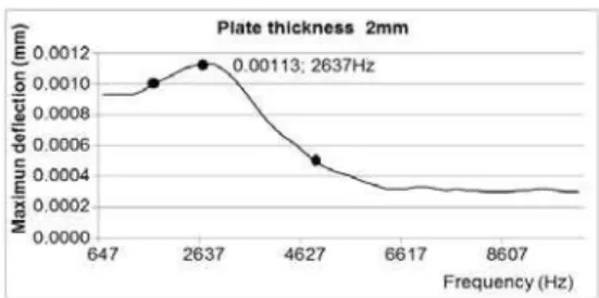
2). This frequency was determined from the simulation results of the deflection for M1=2 mm.
According to the terms of the theoretical study, the maximum relative deflection of the plate designed for the tool was determined 0.0012 mm at 2600Hz, as seen in Figure 3. This value corresponds to what is shown in the graph, which shows a maximum deflection (0.0013 mm) at 2637Hz. These three points are indicated on the graph in Figure 2.To obtain various experimental values, the deflection mode resonance measurements were taken at various frequencies. A reading of 0.0010 mm could be obtained at 2200Hz, and another could be obtained from 0.0005 mm at 4800Hz. Both results corroborate the behaviour of the curve obtained from the simulation. Figure 3 shows the prototype of the manufactured tool, taking into account all the design criteria described.
2.5. Preliminary experiments to characterise the tool operation
To evaluate the behaviour of the prototype tool that was designed, burnishing tests on two pieces of aluminium A92017 and two pieces of steel G10380. The dimensions of said work pieces were 54x 44x15.5mm. The pieces were milled using a hard metal spherical cutter of 8 mm diameter, rotating at 3000min-1 with a feed rate of 330mm/min, a depth of pass of 0.5mm and a lateral swath width of 0.5mm. Conventional burnishing and vibration-assisted burnishing were compared for the same prototype tool. The process parameters used (Table 2) were defined in relation to those obtained by Travieso-Rodriguez, J.A. et al.[1]. To obtain the vibration, the tool was coupled to a vibration generator with coupled plates vibrating at a frequency of 2500Hz, which is defined in the simulation for the thicknesses h, in this study (Figure 2).
Table 2. Burnishing parameters used
Parameter Valour 1 Valour 2
Feed-rate (mm/min), f 500 750
Ball penetration depth (mm), p 0.75 1
Side step width (mm), b 0.080 0.115
After performing both burnishing processes on the work pieces, the resulting surface roughnesses of the burnished specimens were measured. Indicators measured the average surface roughness (Ra) and the maximum roughness total evaluation length (Rz) in two directions that were parallel and perpendicular to the advancement direction of the prior milling operation.
Finally, the surface roughness values obtained with the vibration-assisted tool on the burnished surfaces are better than those of the tool without vibration. For the aluminium work pieces, Ra// was improved by 37%, Rz// was improved by 21%, Ra٣ was improved by 21% and Rz٣ was improved 24% on average. For the steel workpieces, Ra// was improved by 38%, Rz// was improved by 35%, Ra٣ was improved by 33% and Rz٣ was improved by 42% on average.
3. CONCLUSIONS
The changes in the surface roughness obtained when using the vibrations to assist the process were analysed compared to when the process was performed without the assistance of vibration. A method to characterise the plates involved in the design of a tool to be used in the ball-burnishing vibration-assisted process was successfully developed. Reliable numerical solutions were obtained to predict the plate deflection values that can be used to optimise the different basic design parameters: the thickness of the plates, the gap and the working frequency of the vibration generator. A completely new tool for the market was designed, characterised and manufactured.
4. REFERENCES
[1] Travieso-Rodríguez, J. A.; Dessein, G.; González-Rojas, H. A., 2011. Improving the Surface Finish of Concave and Convex Surfaces Using a Ball-burnishing Process. Materials and Manufacturing Processes, Vol.26, Iss.12, pp 1494-1502.
[2] Travieso-Rodríguez, J. A.; 2010. Study to improve the surface finish of complex surfaces, applying a plastic deformation process (Ball-burnishing). PhD thesis, Universitat Politècnica de Catalunya.
[3] B Guo, Q-L Zhao, M J Jackson. Ultrasonic vibration-assisted grinding of microstructured surfaces on silicon carbide ceramic materials. Proceedings of the Institution of Mechanical Engineers, Part B: Journal of Engineering Manufacture March 2012 vol. 226 pp 3553-559.
[4] M R Razfar, P Sarvi, M M Abootorabi Zarchi. Experimental investigation of the surface roughness in ultrasonic-assisted milling. Proceedings of the Institution of Mechanical Engineers, Part B: Journal of Engineering Manufacture September 2011 vol. 225 no. 9 pp 1615-1620.
Figure 2. Sweeping the sinusoidal excitation frequency of the M1plate, contrasted with the
experimentally measured values at 2600Hz.
Figure 3. Prototype of the ball-burnishing vibration-assisted tool.