En vue de l'obtention du
DOCTORAT DE L'UNIVERSITÉ DE TOULOUSE
Délivré par :Institut National Polytechnique de Toulouse (Toulouse INP)
Discipline ou spécialité :
Génie Électrique
Présentée et soutenue par :
M. BUNTHERN KIMle mardi 28 mai 2019
Titre :
Unité de recherche : Ecole doctorale :
Contribution to the design and control of a hybrid renewable energy
generation system based on reuse of electrical and electronics
components for rural electrification in developing countries
Génie Electrique, Electronique, Télécommunications (GEET)
Laboratoire Plasma et Conversion d'Energie ( LAPLACE)
Directeur(s) de Thèse : M. PASCAL MAUSSION MME MARIA PIETRZAK-DAVID
Rapporteurs :
M. HAMID BEN AHMED, ECOLE NORMALE SUPERIEURE M. SERGE PIERFEDERICI, UNIVERSITÉ LORRAINE
Membre(s) du jury :
M. SEDDIK BACHA, INP DE GRENOBLE, Président Mme CATHERINE AZZARO-PANTEL, TOULOUSE INP, Membre
Mme MARIA PIETRZAK-DAVID, TOULOUSE INP, Membre M. PASCAL MAUSSION, TOULOUSE INP, Membre
i
Table of Contents
Acknowledgements ... iv Abstract ... v List of Abbreviations ... ix List of Symbols ... xiList of Figures ... xiii
List of Tables ... xix
General Introduction ... 3
Chapter 1: Reuse for the Solution of Rural Electrification in Developing Countries ... 9
1.1. Introduction ... 9
1.2. Importance of Rural Electrification ... 10
1.2.1. General characteristics of rural energy use ... 10
1.2.2. Benefits of electricity access in rural communities ... 11
1.2.3. Sustainable renewable energy solution for rural electrification ... 14
1.3. Energy Status in Rural Cambodia ... 16
1.3.1. Energy situation ... 16
1.3.2. Rural energy status ... 18
1.3.3. Government policies ... 21
1.3.4. Renewable energies for rural areas ... 23
1.4. Status of E-waste ... 28
1.4.1. Quantity of e-waste worldwide ... 29
1.4.2. Current routes for End-of-Life of EEE ... 31
1.5. E-Waste in Cambodia ... 34
1.5.1. E-waste flow and disposal in Cambodia ... 34
1.5.2. Regulation and framework ... 36
1.6. Second-Life of UEEE ... 38
1.6.1. Impacts of EEE/UEEE ... 38
1.6.2. Reuse vs. recycling vs. buying new EEEs ... 39
1.6.3. Reuse of UEEE as a solution for rural electrification ... 40
1.7. Summary ... 41
Chapter 2: Life Cycle Assessment of Reuse Solution ... 45
2.1. Introduction ... 45
2.2. Life Cycle Assessment Guidelines ... 46
2.2.1. Basic steps in LCA ... 48
2.2.2. Classification and characterization ... 50
2.2.3. Limitations and critical review of LCA methodology ... 52
2.3. LCA of a Small-scale Renewable Energy System Based on Used Components ... 52
ii
2.3.2. Goal and scope definition ... 54
2.3.3. System boundaries ... 55
2.3.4. System Sizing for Life Cycle Inventory ... 58
2.3.5. Life cycle inventory ... 64
2.3.6. Impact assessment results ... 69
2.4. Sensitivity Analysis and Discussion ... 72
2.4.1. Influence of PSUs and UPSs efficiency ... 72
2.4.2. Influence of battery efficiency ... 73
2.4.3. Influence of battery life cycle ... 73
2.4.4. Influence of transportation distance ... 73
2.4.5. Results discussion ... 74
2.5. Summary ... 76
Chapter 3: Second-life Application of Power Supply Units ... 79
3.1. Introduction ... 79
3.2. Computer Power Supply Units (PSUs) ... 81
3.2.1. Computer hardware ... 81
3.2.2. Power supply units ... 82
3.2.3. ATX motherboard and power supply ... 82
3.3. Switching Power Supply ... 83
3.3.1. Power factor correction ... 84
3.3.2. Isolated DC-DC converter topologies ... 85
3.3.3. Types of forward converter based on core reset technique ... 89
3.3.4. Resonant converter ... 91
3.3.5. Control types ... 92
3.4. Modification Processes of PSU circuit board ... 94
3.4.1. General structure of PSU ... 95
3.4.2. Structure of HP305P-00 power supply ... 97
3.4.3. Removing power monitoring functionalities ... 99
3.4.4. RCD demagnetisation circuit and sub-harmonic oscillation issue ... 100
3.4.5. Reducing input voltage range by using primary side center tap ... 107
3.4.6. Variable output control using built-in controller ... 109
3.4.7. Parallel and series combinations of PSUs ... 116
3.5. Second-life Application as MPPT Charge Controller ... 118
3.5.1. Repurposing PSUs as MPPT charge controller ... 119
3.5.2. Experimental tests ... 121
3.6. Summary ... 125
Chapter 4: Novel Structure of a Stand-alone Three-phase Induction Machine Feeding Single-phase Loads ... 129
iii
4.1. Introduction ... 129
4.2. Stand-alone Induction Generators ... 130
4.2.1. Three-phase self-excited induction generator (SEIG) ... 131
4.2.2. Voltage regulation themes for SEIG (review) ... 134
a. Series capacitor scheme ... 135
b. Switched capacitor scheme ... 136
c. Electronic load controller ( ELC) ... 136
d. Fixed capacitor thyristor controlled reactor (FC-TCR) based Static VAR Compensator ... 137
e. Inductively loaded AC/DC converter ... 137
f. Static Compensator (STATCOM ) ... 138
g. AC–DC–AC link converter and other alternatives ... 139
4.2.3. Feeding single-phase loads using three-phase induction generator (review) ... 141
a. Phase balancing methods ... 141
b. TSCAOI topology (inverter-assisted topology) ... 144
4.3. Novel Technique for Single-phase Generator based on TSCAOI Topology ... 145
4.3.1. Dynamic modeling ... 146
a. Classical modeling of induction machine ... 146
b. Experimental setup and model verifications ... 153
4.3.2. Simulation and steady-state study ... 158
a. Simulation models ... 158
b. The effect of phase difference of the excitation sources ... 159
c. Feasible operational region ... 161
d. Choosing the size of parallel capacitor ... 164
e. Generator’s characteristic based on output power ... 166
f. Practical implementation... 168
4.3.3. Experimental tests ... 172
a. Operational speeds (OIATI configuration) ... 172
b. Comparison of OIATI and TSCAOI topologies ... 173
c. Phase difference of excitation sources (OIATI configuration) ... 176
4.4. Summary ... 177
Conclusion and Future work ... 181
References ... 185
iv
Acknowledgements
This research work has been carried out at LAPLACE laboratory (Laboratoire Plasma et Conversion d’Energie) situated in INP-ENSSEIHT, in the CODIASE division. The financial support is provided by the French Embassy in Cambodia through BGF scholarship (Bourses du Gouvernement Français) and partially by LAPLACE. Warm thanks for all.
I am mostly grateful to my supervisor, Pascal MAUSSION, professor at INP-ENSEEIHT, for his excellent supervision and helps during this work. I would also like to express my deep and sincere gratitude to my supervisor, Maria PIETRZAK-DAVID, Professor at INP-ENSEEIHT for her excellent supervision and helps. They provided guidance, encouragement, valuable suggestions and constructive advice on this thesis. I would like to express sincere gratitude to Mrs. Catherine AZZARO-PANTEL, Professor at INP-ENSIACET who has also sacrificed her valuable time in providing me helps and supervision in regard to my work on Life Cycle Analysis.
I would like to say thank to Bruno DAGUES who is in charge of international relations for INP-ENSEEIHT in south-east Asia, who have provided many helps when I needed in terms of accommodation and other necessary requirements for the whole period of my stay in France. I would like to express my sincere thanks to Mr Olivier DURRIEU de MADRON, technician in the laboratory who continuously helped and participated in the technical issues of building the experimentation equipment for the work. I would like to express my deep thanks to all the staffs who work at LAPLACE. Special thanks to CROUS canteen where I enjoy my lunch and dinner.
I would to like to thank the Director and staffs of the Institute of Technology of Cambodia (ITC) that gave me the opportunity to pursue my studies in higher level system. I’m also thankful for all my friends in France, in LAPLACE, in ITC, who are French and other nationalities and who I have interacted with during this meaningful work. My ultimate gratitude goes to my parents without whom I could not be to here by any mean. They have always been providing continuous encouragement, love and support.
I am mostly grateful to Mr. Serge PIERFEDERICI, professor at Université de Lorraine, Mr. Hamid BEN AHMED, from Ecole Normale Supérieure Rennes, and Mr. Seddik BACHA, professor at Grenoble INP, for for their valuable time to participate my thesis examination and their comments, corrections, suggestions on this thesis.
v
Abstract
While the Cambodia’s government is making effort to increase electricity production for its energy demand, it still remains dependent on the existing or the expansion of the centralized grid lines which have high initial investment cost. The temporally solution is to employ a distributed energy generation system which has lower life cycle cost and provides a diversity of technologies to meet the desired applications.
Minimizing environmental impacts represents a major objective of sustainable development considering resources depletion and the limited capabilities of the environment to adapt. The potential of renewable energy resources has been well understood as the solutions to power rural development and to reduce the environmental impacts of energy generation. Due to advance in technologies and increasing consumer demands, there has been a vast amount of electrical and electronic waste which introduces severe impacts on the environment. The current strategies mainly rely on conventional waste collection and processing techniques for material recovery.
This thesis proposed a solution of reusing discarded components in an isolated hybrid renewable energy system as the solution for electrification of rural Cambodia. This is frugal innovation, local solution with local materials for and with local people. A suitable configuration for the proposed system is a solar-hydro hybrid generation system since solar and water resources are plentiful in rural Cambodia. The components that are reused in the solution after being discarded include computer power supply units (PSUs) for the solar part, uninterruptable power supply units (UPSs) and three phase induction machines for the electro-hydro part. Used auto-mobile batteries will be used for the system storage.
The thesis presents in the first part the evaluation of the environmental impacts of the proposed reuse solution for rural electrification. The study of the environmental impacts is based on Life Cycle Assessment (LCA) methodology which compares the life cycle impacts of the proposed solution to that of a conventional solution. Moreover, a sensitivity analysis is achieved in order to evaluate the impacts of uncertainties of the environmental impacts.
The second part of this work deals with the technological aspects of the reuse solution in both theory and experimentation. The first part of this aspect is focused on the repurposing of used computer power supply units (PSUs), through limited modifications of the circuits in order to increase its range of operation. The PSU which usually contains one of a few types of isolated DC-DC converters is repurposed as charge controller with MPPT control in a cheap micro-controller with very good results.
The last part of this thesis studies a new configuration of generators based on re-used three-phase induction motors. The proposed single-three-phase generator is based on a three-three-phase machine in a modified version of the coupling and with a rather uncommon supply. Modelling is highly investigated. An inverter-assisted topology where two windings will be supplied separately by two inverters for excitation and the remaining winding is connected to load. A new modeling of the generator has been studied. The results of simulation were
vi
compared to experimental test results in open loop study. These results have demonstrated the advantages of the new configuration in comparison to the previously proposed inverter-assisted topology in term of efficiency and minimization of torque ripple.
Keywords: Frugal Innovation, reuse, Life Cycle Assessment, power supply units,
second-life, renewable energy, modelling, induction generator, inverter-assisted induction generator.
vii
Résumé
Bien que le gouvernement cambodgien s’efforce d’augmenter sa production d’électricité pour répondre à sa demande en énergie, il reste toujours dépendant de réseau électrique existant ou de l’extension du réseau dont le coût d’investissement initial est élevé. La solution temporelle consiste à employer un système de production d'énergie distribué qui présente un coût de cycle de vie inférieur et introduit une diversité de technologies pour répondre aux applications.
Minimiser les impacts environnementaux représente un objectif majeur du développement durable, compte tenu de l'épuisement des ressources et des capacités d'adaptation limitées de l'environnement. Les ressources en énergies renouvelables ont été bien comprises comme les solutions pour alimenter le développement rural et réduire les impacts environnementaux de la production d’énergie. Suivant les progrès technologiques et de la demande croissante des consommateurs, de grande quantité de déchets électriques et électroniques ont entraîné de graves conséquences pour l’environnement. Les stratégies actuelles reposent principalement sur les techniques classiques de collecte et de traitement des déchets.
Ce travail de thèse proposait une solution de réutilisation des composants électroniques dans un système d'énergie renouvelable hybride isolé pour la solution d'électrification pour la zone rurale. Une configuration choisie pour le système proposé est un système de génération hybride solaire-hydroélectrique, car les ressources solaires et hydrauliques sont abondantes dans les zones rurales du Cambodge. Les composants qui sont réutilisés dans la solution comprennent des blocs d’alimentation d’un PC (PSU) pour la partie solaire, des alimentations sans interruption (UPS) et des machines asynchrone triphasées pour la partie hydraulique. Les batteries automobiles usagées sont utilisées pour le stockage d’énergie.
Ce travail de thèse aborde dans une première partie l’évaluation des impacts environnementaux de la solution de réutilisation proposée. Cette étude repose sur la méthodologie de l’Analyse du Cycle de Vie (ACV) qui compare les impacts du cycle de vie de la solution proposée à ceux d’une solution conventionnelle.
La deuxième partie de ce travail traite des aspects technologiques de la solution de réutilisation, à la fois en théorie et en expérimentation. La première partie de cet aspect concerne la reconversion des blocs d’alimentations usagées. Le bloc d'alimentation, qui contient généralement l'un des quelques types de convertisseurs DC-DC isolés, est réutilisé comme contrôleur de charge, qui est le composant principal du système de générateur photovoltaïque.
La dernière partie de cette thèse décrit une nouvelle configuration de générateur basé sur des moteurs asynchrone triphasés. Le générateur monophasé proposé basé sur une machine triphasée est une version modifiée d'une topologie à base de l’onduleur où deux enroulements sont alimentés séparément par sources d'excitation, et l'autre enroulement est connecté à la charge. Une nouvelle modélisation est proposée. Les résultats de simulation sont comparés aux résultats expérimentaux en alimentation sinus. La comparaison met en évidence une
viii
supériorité de la nouvelle configuration par rapport à l'ancienne en termes de rendement et de minimisation de pulsations de couple.
Mots Clefs: Réutilisation, Analyse du Cycle de Vie, ACV, blocs d’alimentation de
PC, énergies renouvelables, modélisation d’un générateur asynchrone, générateur asynchrone excité par l’onduleur.
ix
List of Abbreviations
ATX: Advanced Technology eXtended motherboard specification. BOS: Balance of System.
CCCSP: Cambodia Climate Change Strategic Plan (2014-2023). CCM: Continuous Conduction Mode.
CMC: Current-Mode Control. DOD: Depth of Discharge. E-waste: Electronics waste.
EAC: Electricity Authority of Cambodia. EDC: Electricité Du Cambodge.
EEE: Electrical and Electronic Equipment. ELC: Electronic Load Control.
EoL: End-of-Life. EV: Electric vehicle.
GDP: Gross Domestic Product.
GERES: Groupe Energies Renouvelables, Environnement et Solidarités. HDI: Human Development Index.
HFO: Heavy Fuel Oil.
HRES: Hybrid Renewable Energy System. IEA: International Energy Agency. IPP: Independent Power Producers. LCA: Life Cycle Assessment.
LCI: Life cycle inventory.
LCIA: Life Cycle Impact Assessment. LPG: Liquefied Petroleum Gas. MDOD: Maximum Depth of Discharge
MOEC: Ministry of Environment of Cambodia. MPPT: Maximum Power Point Tracking. NGO: Non-governmental Organization. NOCT: Nominal Operating Cell Temperature.
OIATI: One-Isolated-And-Two-Isolated-Inputs generator configuration. PCB: Printed Circuit Board.
PFC: Power Factor Correction. PSU: Power Supply Unit. PV: Photovoltaic.
RCD: Resistor, Capacitor and Diode clamping circuit.
REE: Rural Electricity Enterprises. SCIM: Squirrel Cage Induction Machine. SEIG: Self-Excited Induction Generators.
SETAC: Society of Environmental Toxicology and Chemistry. SLI: Starting-Lighting-Ignition (batteries).
x
SVC: Static VAR Compensator.
TSCAOI: Two-Series-Connected-And-One-Isolated generator configuration. UEEE: Used Electrical and Electronic Equipment.
UNDP: United Nations Development Programme. UNEP: United Nations Environmental Programme. UNFCCC: United Nations Convention on Climate Change. UNU: United Nation University.
UPS: Uninterruptable Power Supply Unit.
US-EPA: Environmental Protection Agency of the USA. VEB: Vented lead-acid Battery.
VMC : Voltage-Mode Control.
VRLAB: Valve-Regulated Lead-Acid Battery. WEEE: Waste Electrical and Electronic Equipment.
xi
List of Symbols
Apv PV panels surface area.
Cbat,Ah Batteries capacity in Ah.
Cbat,Wh Batteries capacity in Wh.
C Excitation capacitor.
Ceff The equivalent excitation capacitor.
Cmin The minimum requirement capacitor value for SEIG operation.
D Duty cycle of PWM signal / viscous friction coefficient.
Edc Daily energy consumption by batteries.
Ebat Daily energy needed to charge batteries.
EPV,STC Daily energy generated by PV panels at standard test conditions.
[Ir] Rotor current vector in ‘abc’ frame, [ira, irb, irc]T
[Is] Stator current vector in ‘abc’ frame, [isa, isb, isc]T
[Ir_dq0] Rotor current vector in ‘dq0’ frame, [ird, irq, ir0]T
[Is_dq0] Stator current vector in ‘dq0’ frame, [isd, isq, is0]T
Ie1, Ie2 Excitation currents. (Ie1= isa ; Ie2 = isb)
iC Capacitor current.
iL Load current
J Overall system inertia.
[Ls], [Lr] Stator and rotor inductance matrix.
lsp Stator phase proper inductance.
lsl Stator phase leakage inductance.
lrp Rotor phase proper inductance.
lrl Rotor phase leakage inductance.
Ls, Lr Stator and rotor cyclic inductance.
Ls0, Lr0 Stator and rotor inductances corresponding to homopolar components.
M Mutual cyclic inductance
Msr Maximal mutual inductance between a stator and a rotor phases.
mpv PV panels mass.
NOCT Normal Operating Cell Temperature.
Np Number of primary turn of a transformer.
Ns Number of secondary turn of a transformer. ηinv Inverter efficiency.
ηbat Batteries efficiency.
ηpv PV generator efficiency.
ηconversion PV generator conversion efficiency which include charge controller efficiency
(ηchargecontroller), dirt on the PV surface, mismatched modules (ηdirt,mismatched), and
module temperature (ηcellTemp).
P Number of poles.
Pinv Inverter input power.
Ploadpeak Peak load power consumption.
xii
PPV PV power rating (Wp).
[P(θ)] Park transformation matrix.
R(θ) The transformation matrix.
Rs, Rr Stator and rotor phase resistance.
RL Load resistance.
S Solar insolation (kW/m2).
Ta Algorithm sampling period (MPPT algorithm).
Tcell PV cell temperature (oC).
Tamb Ambient temperature (oC).
Te Electromagnetic torque developed in induction generator.
Tp Torque given by prime mover.
[u] Input vector in state-space model.
vcon Control signal voltage.
Vdc Input voltage (of a PSU main converter).
Vds Voltage across D and S pin of a MOSFET.
Vreset Voltage applied over the magnetizing inductor during OFF time.
Vpv Output voltage of a PV generator.
[Vs] Stator voltage vector in ‘abc’ frame, [vsa, vsb, vsc]T
[Vr] Rotor voltage vector in ‘abc’ frame, [vra, vrb, vrc]T
[Vs_dq0] Stator voltage vector in ‘dq0’ frame, [vsd, vsq, vs0]T
[Ve] Input voltage vector in ‘abc’ frame, [vsa, vsb, 0]Tor [Ve1, Ve2, 0]T
Ve1, Ve2 Excitation voltage sources. (Ve1= vsa ; Ve2 = vsb)
[x] State vector in state-space model.
∆α Duty cycle step (MPPT algorithm).
[Φs] Stator magnetic flux vector in ‘abc’ frame, [ϕsa, ϕsb, ϕsc]T
[Φr] Rotor magnetic flux vector in ‘abc’ frame, [ϕra, ϕrb, ϕrc]T
[Φs_dq0] Stator magnetic flux vector in ‘dq0’ frame, [ϕsa, ϕsb, ϕsc]T
[Φr_dq0] Rotor magnetic flux vector in ‘dq0’ frame, [ϕra, ϕrb, ϕrc]T
θ, ω Rotor electrical angular position and speed.
θs,θr Electrical angular position between magnetic field and stator and rotor.
xiii
List of Figures
Fig. 1- 1: (a) Traditional cook stove; (b) LPG stoves; (c) high-efficiency cook stove. [104]... 11
Fig. 1- 2: Per capita energy consumption and the Human Development Index (HDI). [108] ... 13
Fig. 1- 3: Correlation of electricity consumption and education index based on 120 countries. [114] 13 Fig. 1- 4: Electricity generated by types of plants in 2010 and 2015 (million kWh). [127] ... 17
Fig. 1- 5: Traditional cooking stove by burning charcoal and wood. [130] ... 19
Fig. 1- 6: Energy sources used for cooking by percentage of population in urban and rural areas of Kampong Speu. [130] ... 19
Fig. 1- 7: Energy sources used for cooking by percentage of population in urban and rural areas of Svay Rieng. [130] ... 20
Fig. 1- 8: Usage lead-acid batteries in rural Cambodia: (a) common electronic appliances, (b) transport of batteries to, (c) batteries charging station. [130] ... 21
Fig. 1- 9: Energy sources used for lighting and other electric appliances by percentage of population in urban and rural areas of Kampong Speu. [130] ... 21
Fig. 1- 10: Energy sources used for lighting and other electric appliances by percentage of population in urban and rural areas of Svay Rieng. [130] ... 21
Fig. 1- 11: (a) Kamchay hydro dam (Kampot); (b) Kirirom 3 dam (Koh Kong). ... 24
Fig. 1- 12: (a) Stung Atay hydro dam (Pursat) ; (b) Stung Tatay hydro dam (Koh Kong) ... 25
Fig. 1- 13: Solar resource map of Cambodia. [146] ... 26
Fig. 1- 14: Installation of World Bank’s SHS in one the 12,093 households. [147] ... 27
Fig. 1- 15: Wind resource at 65m altitude. [151] ... 27
Fig. 1- 16: Pile of e-waste in Switzerland (Greenpeace). [152] ... 28
Fig. 1- 17: Global EEE put in market in 2012 (million tons) (UNU regional e-waste monitor). [156] 30 Fig. 1- 18: Yearly e-waste generated per inhabitant (Kg/inh.) (UNU global e-waste monitor). ... 30
Fig. 1- 19: E-waste generated by continent in 2014. (UNU global e-waste monitor)... 31
Fig. 1- 20: Flow of EEE/UEEE in Cambodia. [157]... 35
Fig. 1- 21: End-of-life of WEEE in Phnom Penh at a glance: (a) second-hand shop, (b) repair shop, (c) waste buyer, (d) informal e-waste transportation, (e) transport of computer parts, (f) dumping site and waste pickers. [158, 160] ... 35
Fig. 1- 22: Proposed renewable energy generation system for rural electrification. ... 40
Fig. 2- 1: Product life cycle. [212] ... 47
Fig. 2- 2: Basic steps in standard LCA ... 48
Fig. 2- 3: Products life cycle and flows of materials/energy to the environment from [219]. ... 50
Fig. 2- 4: Classification and characterization of impacts. [222] ... 51
Fig. 2- 5: PV generation system using conventional solution. ... 53
Fig. 2- 6: Proposed PV generation system based on reuse solution. ... 53
Fig. 2- 7: Load profile of a single village in Chiangria, Thailand. [227] ... 54
Fig. 2- 8: System boundary of life cycle assessment for the conventional solution. ... 55
Fig. 2- 9: System boundary of life cycle assessment for the reuse solution. ... 55
Fig. 2- 10: Inverter efficiency against rated output power. [232] ... 58
Fig. 2- 11: Days of battery storage needed for a stand-alone system with 95% and 99% system availability. Peak sun hours are for the worst month of the year. [230] ... 59
Fig. 2- 12: Tear down of a 700VA UPS (battery is not shown). ... 63
xiv
Fig. 2- 14: Normalised midpoint categories impacts scores of lead-acid battery production (per 1kg
battery). ... 68
Fig. 2- 15: Normalised midpoint categories impacts of lead-acid battery life cycle at difference ratio of primary to secondary lead. (Per 1kg battery) ... 68
Fig. 2- 16: Normalized midpoint categories impacts scores of conventional PV system over 20 years. ... 70
Fig. 2- 17: Normalized impacts scores in different midpoint categories for reuse solution. ... 71
Fig. 2- 18: Normalized impacts scores comparison of conventional and reuse solutions. ... 71
Fig. 2- 19: Comparison of influence of parameters to the impact results. ... 75
Fig. 2- 20: Comparison of normalised impacts scores by doubling battery lifetime in conventional solution. ... 75
Fig. 3- 1: Proposed PV generation system based on repurposed power supply units (and used batteries and UPS units). ... 80
Fig. 3- 2: Open computer case. ... 81
Fig. 3- 3: Summary of ATX chassis features. [313] ... 83
Fig. 3- 4: The 4-pin 12V auxiliary power connector on a motherboard provided by ATX12V power supply. [309] ... 83
Fig. 3- 5: Simplified block diagram of off-line AC/DC switched-mode power supplies. [314] ... 84
Fig. 3- 6: Circuit diagram of a passive PFC where 115Vac or 230Vac input option can be selected manually. ... 85
Fig. 3- 7: Bulky PFC inductor mounted to the case of a power supply. ... 85
Fig. 3- 8: Active PFC circuit diagram. ... 85
Fig. 3- 9: Flyback converter topology. ... 86
Fig. 3- 10: Forward converter topology. ... 87
Fig. 3- 11: Push-pull converter topology. ... 88
Fig. 3- 12: Half-bridge converter topology. ... 88
Fig. 3- 13: Full-bridge converter topology. ... 89
Fig. 3- 14: Forward converter with tertiary winding... 89
Fig. 3- 15: Clamp reset forward converter: (A) RCD clamp; (B) active clamp. ... 90
Fig. 3- 16: Two-switch forward converter. ... 91
Fig. 3- 17: Half-bridge converter: (A) serial resonant; (B) parallel resonant. ... 91
Fig. 3- 18: Half-bridge LLC resonant converter ... 92
Fig. 3- 19: Voltage-mode control principle in a Buck converter. ... 93
Fig. 3- 20: Current-mode control principle in a boost converter. ... 93
Fig. 3- 21: Wire color coding of ATX power supplies. ... 95
Fig. 3- 22: Common block diagram of power supply. ... 96
Fig. 3- 23: Dell HP305P-00 power supplies. ... 97
Fig. 3- 24: HP305P-00 internal circuit board. ... 97
Fig. 3- 25: HP305P-00 functional block diagram. ... 98
Fig. 3- 26: Main power conversion stage in HP305P-00. ... 98
Fig. 3- 27: Fault protection and power monitor circuits. ... 99
Fig. 3- 28: Transformer core magnetization: (A) without core reset; (B) with core reset. [325] ... 100
Fig. 3- 29: RCD clamp forward converter. ... 101
Fig. 3- 30: Operating waveforms: transistor drain voltage and transformer magnetizing current. [326] ... 102
Fig. 3- 31:PWM signal at input voltage of: (a) 140V; (b) less than 120V (sub-harmonic oscillation). ... 104
xv
Fig. 3- 32: Response of inductor current to disturbance for different duty cycles. [330] ... 105
Fig. 3- 33: Clamp voltage Vsn at Vin > 120V; (50V/div) ... 105
Fig. 3- 34: Clamp voltage Vsn at: (a) Vin < 120V; (b) Vin < 110V. (50V/div) ... 106
Fig. 3- 35: Slope compensation methods: (a) No compensation; (b) compensation added to control voltage; (c) compensation added to current sense. [331] ... 106
Fig. 3- 36: Slope compensation methods using UC3842/3: (a) using voltage control signal; (b) using current sense. [331] ... 107
Fig. 3- 37: Power supply’s output load regulation characteristic at different input levels when center-tap pin of the transformer is used. ... 108
Fig. 3- 38: Duty cycle of the power converter at different output current (For Vin=60V, the sub-harmonic oscillation occurs at around the output current of 7A) ... 109
Fig. 3- 39: Main controller diagram of H305P-00. ... 110
Fig. 3- 40: (a) The initial feedback circuit; (b) Equivalent circuit. ... 110
Fig. 3- 41: Modified feedback circuit. ... 111
Fig. 3- 42: Adding resistors to the feedback on the circuit board: from above (left); from below (right). ... 111
Fig. 3- 43: Steady state relationship between Vo and V1 (at 6Ω load). ... 112
Fig. 3- 44: Simulated transient responses of Vo to: (A) change in (V1) with 3Ω load; (B) load transition, 12Ω-3Ω. ... 112
Fig. 3- 45: Experimental transient responses of Vo to: (A) change in (V1) with 3Ω load; (B) load transition, 12Ω-3Ω. ... 112
Fig. 3- 46: Using current loop for output current control. ... 113
Fig. 3- 47: (A) Feedback modification for current control; (B) an additional circuit to supply the feedback circuit. ... 113
Fig. 3- 48: Test bench: Control of alternator field current using the modified PSU. ... 114
Fig. 3- 49: Alternator output voltage characteristics. ... 114
Fig. 3- 50: Relationship between output current (Io) and input voltage Vi in steady state for resistive load and inductive load. ... 115
Fig. 3- 51: Simulated step response of output current (Io) for (A) resistive load (3 Ω) and (B) inductive load (3Ω, 13mH). ... 115
Fig. 3- 52: Experimental step response of output current (Io) for (a) resistive load and (b) inductive load (alternator’s rotor). ... 115
Fig. 3- 53: PWM signal and output current waveform for (a) resistive load and (b) inductive load. . 116
Fig. 3- 54: (a) Parallel-input connection; (b) Converter-per-panel approach. ... 117
Fig. 3- 55: (a) Current distribution control of parallel-input-parallel-output connection of PSUs [337]; (b) voltage distribution control of parallel-input-series-output connection of PSUs [339]. ... 118
Fig. 3- 56: Association of identical PSUs using the same switching signal without current or voltage distribution control. ... 118
Fig. 3- 57: Solar-pico-hydro hybrid energy generation system. ... 119
Fig. 3- 58: Flow chart of P&O and INC algorithms. ... 120
Fig. 3- 59: MPPT converter block diagram. ... 120
Fig. 3- 60: Arduino programmed MPPT control: voltage and current sensing network and driver interface for PSU. ... 121
Fig. 3- 61: PV generator output voltage response to step transition of duty cycle. ... 122
Fig. 3- 62: PV generator output current response to step transition of duty cycle. ... 122
Fig. 3- 63: Solar panels P-V curve at two different irradiance level. ... 123
Fig. 3- 64: Performance of PSU with MPPT control in load change and incident light change (INC algorithm). ... 123
xvi
Fig. 3- 65: Steca’s Solarix MPPT 2010 module. ... 123
Fig. 3- 66: System efficiency (ratio of output power and solar insolation power) of Steca MPPT module and modified PSU with MPPT control. ... 124
Fig. 3- 67: Solar radiation profile in Phnom Penh, measured in a day time in August, 2014 (local time) ... 124
Fig. 4- 1: Self-excited IG with capacitor banks. [411] ... 131
Fig. 4- 2: Per phase equivalent circuit for the induction machine. [411] ... 133
Fig. 4- 3: Magnetizing curve of the induction generator. [411] ... 133
Fig. 4- 4: Series compensation with short shunt connection [423, 424]. ... 136
Fig. 4- 5: (a) Thyristor controlled converter based ELC; (b) Rectifier/chopper based ELC. ... 137
Fig. 4- 6: (a) FC-TCR static VAR compensator; (b) per phase operation. [436] ... 137
Fig. 4- 7: SVC based on controlled rectifier. [438] ... 138
Fig. 4- 8: (a) Voltage-type STATCOM [439]; (b) current-type STATCOM. [440] ... 138
Fig. 4- 9: IMC power circuit connected between SEIG and a load. [411] ... 139
Fig. 4- 10: Proposed WECS based on the SCIG. [446] ... 140
Fig. 4- 11: (a) The Fukami connection; (b) the Smith connection. [449] ... 142
Fig. 4- 12: Star connected generators with one capacitor. [449]... 142
Fig. 4- 13: Delta connected generators with one capacitor. [449] ... 142
Fig. 4- 14: Delta connected generators with two capacitors. [449]... 142
Fig. 4- 15: Delta connected generators with two capacitors: (a) The C–2C connection [453]; (b) Current injection transformer. [454] ... 143
Fig. 4- 16: The back-to-back topology. [458, 459] ... 143
Fig. 4- 17: The VSI-DL topology. [460, 461] ... 144
Fig. 4- 18: The STATCOM based topology. [463] ... 144
Fig. 4- 19: Inverter-assisted single-phase IG. ... 145
Fig. 4- 20: TSCAOI configuration for three-phase IG. ... 145
Fig. 4- 21: Proposed modified-TSCAOI topology (OIATI topology). ... 146
Fig. 4- 22: Voltages and currents in windings of cage induction machine. ... 147
Fig. 4- 23: Angular representation of the axis systems in the electrical space. ... 149
Fig. 4- 24: Simulink model of the induction generator. ... 153
Fig. 4- 25: Experimental setup. ... 154
Fig. 4- 26: Transient response of the input winding currents (Ie1, Ie2): (a) test results; (b) simulated results. ... 155
Fig. 4- 27: Transient response of the output winding current (Isc): (a) test result; (b) simulated result. ... 156
Fig. 4- 28: Transient response of the output voltage (Vsc): (a) test result; (b) simulated result. ... 156
Fig. 4- 29: Test and simulated steady-state results of input active (P) and reactive power (Q) at different rotation speeds. ... 157
Fig. 4- 30: Test and simulated steady-state results of input currents (a) and output voltage (b) at different rotation speeds. ... 157
Fig. 4- 31: Test and simulated steady-state results of load torque of the generator at different rotation speeds. ... 157
Fig. 4- 32: Simplified Power-speed characteristics for a turbine in a small hydro scheme. [418] ... 158
Fig. 4- 33: Simulation model of the TSCAOI topology... 158
Fig. 4- 34: Simulation model of the OIATI topology. ... 159
Fig. 4- 35: The torque-speed curve of a constant-power load. ... 159
xvii
Fig. 4- 37: Power vs. phase difference of Ve1 and Ve2 (a); Voltages vs. phase difference of Ve1 and Ve2 (b). (630W mechanical input) ... 160 Fig. 4- 38: Torque ripple vs. phase difference of Ve1 and Ve2. (OIATI vs. TSCAOI configuration) 161 Fig. 4- 39: Real/reactive powers absorbed by excitation winding (Pe; Qe) vs. rotation speed (rpm). (Output load at 50W and 500W; OIATI configuration) ... 161 Fig. 4- 40: Stator winding currents vs. rotation speed (rpm). (Output load of 50W and 500W; OIATI) ... 162 Fig. 4- 41: TSCAOI configuration: Real/reactive powers absorbed by excitation winding vs. rotation speed (rpm). (Output load at 50W and 500W) ... 162 Fig. 4- 42: TSCAOI configuration: stator winding currents vs. rotation speed (rpm). (Output load at 50W and 500W) ... 163 Fig. 4- 43: Total active power generated by the generator in the OIATI (blue) and TSCAOI (red) configuration. (Output load at 50W and 500W) ... 163 Fig. 4- 44: Excitation voltages in OIATI configuration (Ve1/Ve2)(blue) and TSCAOI configuration (Ve1)(red). (Output load at 50W and 500W) ... 163 Fig. 4- 45: Output voltage for various capacitor values as a function of output power. (OIATI and TSCAOI topologies) ... 164 Fig. 4- 46: Excitation winding currents in the proposed configuration for various capacitor values as a function of output power. (OIATI topologies) ... 165 Fig. 4- 47: Output winding current and the sum of all winding currents (Isabc = Ie1+Ie2+Isc) for various capacitor values as a function of output power. (OIATI topologies) ... 165 Fig. 4- 48: Winding currents for various capacitor values as a function of output power. (TSCAOI configuration) ... 165 Fig. 4- 49: Input winding currents, Ie1 (left), Ie2 (right) vs. speed at different load outputs. (OIATI configuration) ... 166 Fig. 4- 50: Input winding currents comparison, Ie for OIATI configuration and Ie1 for TSCAOI configuration. ... 167 Fig. 4- 51: Active power given by input sources vs. speed at different load outputs. (OIATI
configuration) ... 167 Fig. 4- 52: Active power given by input source vs. speed at different load outputs. (TSCAOI
configuration) ... 167 Fig. 4- 53: Excitation voltage sources vs. speed at different load outputs. (Ve for OIATI configuration and Ve1 for TSCAOI configuration) ... 168 Fig. 4- 54: PWM inverter driving one of the exciting windings. ... 168 Fig. 4- 55: Close-loop PI controller. ... 169 Fig. 4- 56: Excitation currents vs. output power (a); Real power of excitation windings vs. output power (b). (OIATI and TSCAOI topologies) ... 169 Fig. 4- 57: Generator efficiency vs. output power. ... 170 Fig. 4- 58: Load transition (TSCAOI): (a) output power (in W); (b) output voltage Vs (Feedback Vfb and reference voltage Vref) (in V); (c) winding current (in A). ... 170 Fig. 4- 59: Load transition (OIATI): (a) output power (in W); (b) output voltage Vs (Feedback Vfb and reference voltage Vref) (in V); (c) winding currents (in A). ... 171 Fig. 4- 60: Wind speed transition (TSCAOI): (a) wind speed (in m/s); (b) rotation speed (in rpm); (c) output voltage Vs and reference voltage Vref (in V); (d) winding current (in A). ... 171 Fig. 4- 61: Wind speed transition (OIATI): (a) wind speed (in m/s); (b) rotation speed (in rpm); (c) output voltage Vs and reference voltage Vref (in V); (d) winding currents (in A). ... 172 Fig. 4- 62: Test and simulated steady-state results of input currents (a) and input reactive power (b) at different rotation speed. ... 173
xviii
Fig. 4- 63: Test and simulated steady-state results of input active power (a) and input mechanical power (b) at different rotation speed. ... 173 Fig. 4- 64: Test and simulated steady-state results of input current (a) and input active and reactive power (b) at different rotation speed at 350W load (TSCAOI topology). ... 174 Fig. 4- 65: Steady-state test results of input current (left) and input voltage (right) at different rotation speeds for 100W and 350W loads. (TSCAOI and OAITI configuration) ... 174 Fig. 4- 66: Comparison of experimental efficiency of TSCAOI and OIATI configurations at different rotation speed for a 350W load. ... 175 Fig. 4- 67: Generator driving torque fluctuation in TSCAOI configuration: (a) at 1500rpm; (b) at 1700rpm. ... 175 Fig. 4- 68: Generator driving torque fluctuation in OIATI configuration: (a) at 1500rpm; (b) at
1620rpm. ... 175 Fig. 4- 69: Steady-state test results of input currents (a) and input active powers (b) at different phase difference of input voltage sources for 100W and 350W load, both at 1520rpm. ... 176 Fig. 4- 70: Steady-state test results of mechanical input power (a) and electrical output power (b) at different phase difference of input voltage sources for 100W and 350W load. ... 176 Fig. 4- 71: Generator’s experimental efficiency at different phase difference of input voltage sources for 100W and 350W load. ... 177
xix
List of Tables
Table 1- 1: Data of electricity sector of Cambodia at a glance (EAC annual report). [127]... 18
Table 1- 2: Number of Villages Covered by licenced areas by end of 2015 (EAC). [127] ... 18
Table 2- 1: Number of battery cycles as a function of depth of discharge DOD (manufacturer’s data). [231] ... 56
Table 2- 2: Lead-acid battery characteristics. [230] ... 57
Table 2- 3: Component service time and replacement. ... 57
Table 2- 4: Transportation mode and distance. ... 58
Table 2- 5: Parameters of components in the conventional solution. ... 62
Table 2- 6: Component sizing of the conventional solution. ... 62
Table 2- 7: Parameters of the components of the reuse solution. ... 63
Table 2- 8: Component sizing of the reuse solution. ... 63
Table 2- 9: Component sizing (reuse solution vs. conventional solution). ... 63
Table 2- 10: LCI of 2500WAC Inverter (Disassembly of inverter and weighing), based on data collected in 2001, from Mastervolt Sunmaster 2500. [234] ... 65
Table 2- 11: Inventories data for Inverter, charge controller and PV panels. ... 65
Table 2- 12: Impacts of inverter and PV module life cycle (Impact 2002+) ... 65
Table 2- 13: Material composition of the lead-acid batteries in percentage of battery mass from difference references. ... 66
Table 2- 14: Material composition in percentage of mass of lead-acid battery ([238-242]) and the corresponding database of material production. ... 67
Table 2- 15: Energy requirement in battery manufacturing process ... 67
Table 2- 16: Ecoinvent data employed for recycling process of battery. ... 67
Table 2- 17: Ecoinvent database used for impacts characterisation in reuse solution. ... 69
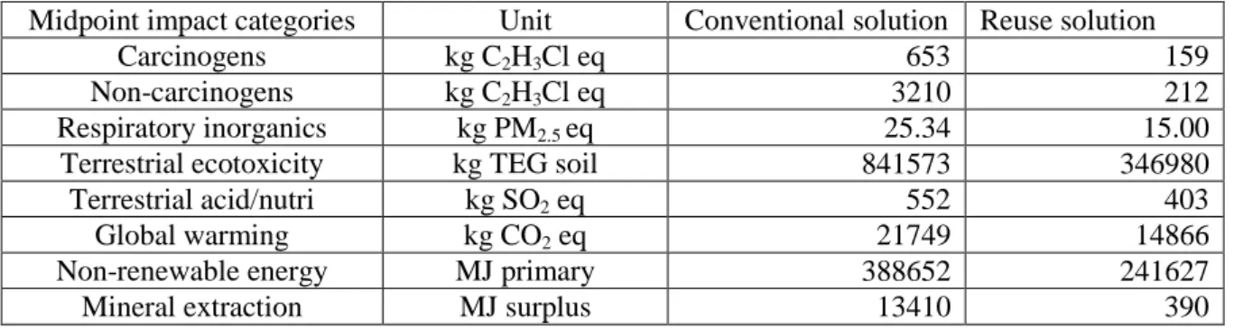
Table 2- 18: Impacts comparison of the conventional and the reuse solutions for selected midpoint categories. ... 72
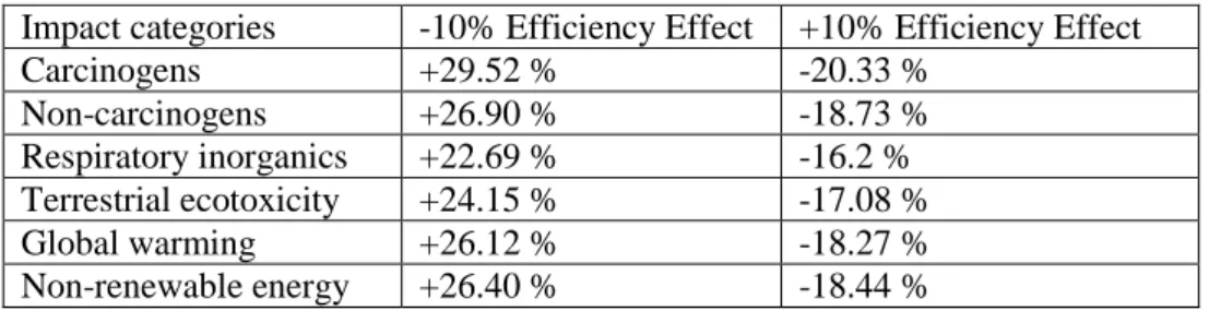
Table 2- 19: Influence of PSUs and UPSs efficiency on the impact result of reuse solution. ... 73
Table 2- 20: Influence of storage batteries efficiencies on the impact result of reuse solution. ... 73
Table 2- 21: The influence of batteries life time on the impacts result of reuse solution ... 74
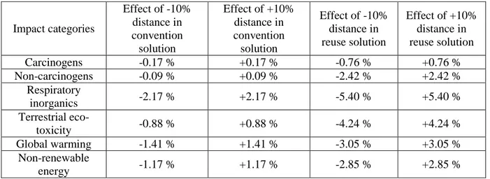
Table 2- 22: The influence of batteries life time on the impacts result of both solutions ... 74
Table 3- 1: A sample of discarded power supplies found in recycles bins. ... 96
Table 4- 1: Induction generator parameters. ... 155
1
3
General Introduction
In many developing countries including Cambodia, the majority of the population in rural area lacks sufficient access to sustainable, reliable and effective energy systems. Today, the most fundamental energy access is distributed in electricity form which is very easy to be transformed into the desirable types of energy that are useful to our activities. Access to affordable and reliable energy services is fundamental to reducing poverty and improving health, increasing productivity, enhancing competitiveness and promoting economic growth. However, extension of centralized grid electricity lines to rural area in developing countries faces significant challenges including high construction cost of transmission lines, transmission losses and is nearly impossible for utilities to be profitable due in large part to low rural household energy consumption and insufficient population densities. The temporally solution is distributed energy micro-generation system which has lower life cycle cost and provides a diversity of technologies to meet the desired applications in rural communities.
Minimizing environmental impacts represents a major objective of sustainable development considering resources depletion and the limited capabilities of the environment to adapt. The potential of renewable energy technologies to power rural development has been well understood as the solutions to power rural development and to reduce the environmental impacts of energy generation. Because renewable energy is regionally diverse, choosing the appropriate system generally depends on the local availability of renewable energy resources and the characteristics of the local electricity demand. Cambodia is one the Southeast Asia countries having one of the richest countries in hydropower resources due to its river system. While the Cambodia government is making effort to increase electricity production for its energy demand by investment in new hydro and coal power plants, it still remains dependent on the existing or the expansion of the centralized grid line. Although photovoltaic lighting systems have paved the way in some rural village, the solution of providing electricity access using distributed energy generation system based on renewable energies has not been significantly explored for the rural communities in Cambodia. Several barriers might be the obstacles for adoption of such the system including lack of adequate infrastructure and appropriate technology, technical skills, existing knowledge on the management, operation and regulation of RETs and substantial investment costs.
This thesis proposed a novel solution of reusing discarded components in isolated renewable energy systems for electrification for rural Cambodia first. This solution is interesting not only for Cambodia but for any countries or regions which are rich in solar or hydro resources. A suitable configuration for the proposed system is a solar-hydro hybrid generation system since solar and hydro (mostly in highland regions) resources are plentiful in rural Cambodia. The components which can be reused include computer power supply units (PSUs) as DC-DC converters, uninterruptable power supply units (UPSs) as inverters, three phase induction machines as induction generators, and car batteries as an energy storage. Such solution helps to provide an intermediate, affordable and sustainable energy access solution for rural
4
communities. The cost of the system can be cut due to reuse of discarded components instead of brand new devices.
With the rapid expansion of technological development, innovation and consumer demand, various electronic equipment has been significantly improved, results in the shorter life of electronic products, and higher amounts of waste electrical and electronic equipment. The current strategies mainly rely on conventional waste collection and processing techniques for material recovery. The proposed solution can also provide extra tool to solve the growing e-waste problem and eliminate the impacts due to production of new components for the system.
The objectives of this thesis work were to 1) evaluate the environmental impacts of the proposed reuse solution for rural electrification while making the comparison with the impacts of the same system using newly made components; 2) address the technological aspects of the reuse solution in theory, simulations and experimentation. The comparative study of environmental impacts is based on Life Cycle Assessment (LCA) methodology that encompasses all the potential impacts throughout the product chain. LCA is a holistic and standardized tool that makes comparisons complete and less subjective. Nevertheless, some inventories data were based on assumption and data extrapolation due to the lack of specific information from database and literature. The sensitivity analysis is made to assess the effects of the assumptions and of possible variations in the collected data on the results.
Since the proposed reuse solution is based on a solar-hydro hybrid generation system, the technological study of the system can be divided into two parts: the first part focus on the repurposing of used computer power supply units (PSUs) which is the main component in solar photovoltaic (PV) generator system; the second part studies the generator for ‘pico-hydro’ plant that is based on discarded induction motors and hydro turbines. Power supply units usually contain one of a few types of isolated DC-DC converters. This kind of converter can be repurposed as ‘Electronic Load Controller’ for voltage regulation of induction generator, auto-mobile alternator output controller, and mainly as charge controller in photovoltaic generator system. In order to optimize the energy extraction from the sun in PV generator, the ‘Maximum Power Point Tracking’ (MPPT) control has to be implemented with a cheap easy-to-program microcontroller. This controller can be implemented with the power supply units which are lightly changed by removing or adding a few electronic components.
Though purposed built induction generators are expensive, three-phase induction motors can be used as generator when the drive condition is right. Three-phase induction motors are mass produced and widely used in the factories, power tools, and home appliances. For this reason, it is quite cheap, easily available, and can be found easily at the waste collection site all over the world. Widespread exploitation of stand-alone renewable systems has led to popular use of self-excited induction generators (SEIGs) for supplying electrical energy in rural areas. However, SEIGs suffer from unsatisfactory voltage regulation and frequency variations. Several techniques of voltage and frequency controls using power semiconductor devices and reactive elements have been studied widely by the researchers over the years. In addition to review of these strategies, a novel configuration of single-phase generator based
5
3-phase induction machine was presented as a new alternative based on the recent two-series-connected and-one-isolated or ‘TSCAOI’ configuration.
Dissertation structure
This thesis manuscript is divided in four main chapters, following a general introduction and leading to overall conclusions and perspectives. The first chapter presents the current status of rural electrification in Cambodia, its electrification policy, and its renewable energy resources. This chapter also describes the current situation of electronic waste worldwide and in Cambodia. This review provided the justifications for the introduction of the solution for rural electrification by reusing discarded electronic and electrical devices in a hybrid renewable energy system.
The second chapter aims to evaluate the environmental aspect of a proposed stand-alone renewable energy system using LCA methodology. The environmental impact associated with the life cycle conventional renewable system based on newly made components is also evaluated for comparison. The evaluation processes will follow these important steps: defining functional unit and system boundaries, system sizing and defining the life cycle inventories, and impact assessments. The sensitivity analysis of uncertain or assumed parameters is made to verify the reliability of the impact assessments.
The technological aspect of the proposed solution focused on the refurbishing and repurposing processes of the used power supply units is addressed in chapter 3. This chapter introduces the general structure, converter topologies, and type of control systems commonly found in power supply units. The main part of this chapter focuses on the general conception and common techniques to identify the issues and modify the structure of the power supply units to operate as a general purpose DC-DC converter. The power supply unit is successful converted to a MPPT controller providing optional energy transfer from the PV generator to load.
The fourth and last chapter proposes a new variable excitation technique derived from the TSCAOI topology for the induction generator of the pico-hydro plant. The overview of various voltage regulation techniques for three-phase and single-phase loads are first presented to illustrate the different advantages and disadvantages of each technique. The proposed single-phase generator based on three-phase generator is a modified version of an inverter-assisted topology where two winding will be supplied separately by two inverters for excitation, and the remaining winding is connected to load. Mathematical model of the generator is first explored. The performance of the proposed topology is studied in open loop by computer simulation and validated using experiments and a lot of characterization results are provided.
7
Chapter 1
Reuse for the Solution of Rural Electrification
in Developing Countries
9
Chapter 1: Reuse for the Solution of Rural
Electrification in Developing Countries
1.1. Introduction
Energy is considered to be one of the most important key drivers in economic development and human well-being of modern society. Electric energy is the final and most volatile energy form providing the most convenient way to transport and distribute energy to any remote areas. While most advanced economies have required secure access to sufficient sources of energy to drive their development and economic growth, millions of people in poor countries are in urgent need of electricity access.
Having access to modern energy services in rural communities drives economic growth, educational opportunities, and eliminate negative public health and environmental impacts. The first obvious solution is to extend the centralized electricity grid to remote areas. This solution faces several challenges including high initial cost, and low profit in return. An alternative is to rely on isolated energy micro-generation system which could provide communities immediate electricity access with lower investment cost without long delay. In many remote regions, renewable energy resources, such as solar, wind, and hydropower has the potential for a more environmental friendly and lower initial cost generation system. Today, more and more people around the world rely on electric and electronic devices such as computer, phones, fans (in hot countries) and batteries as an essential part of their everyday lives. However, the rate at which they purchase and discard these devices is having a serious impact on our planet because they are being discarded before their useful lifetime. Reusing the devices for either the same usage or different applications with some repair and refurbishment extends their effective lifetime. Reusing products could be preferable over other end-of-life strategies as this is the least energy and material intensive solution.
Currently, reuse is often practiced by retailers driven by market demands for cheaper second-hand products. Often overlooked, some parts or components of a device can be repurposed for completely different applications. While it is possible to repair the whole devices, some components of the products such as power supplies, batteries, and electric motors have the potential for reuse as components in small renewable energy system for rural area. All these points will be developed in the following chapters, but the first one hereafter will be devoted to rural electrification and e-waste in terms of state of the art in general and in the context of the country in interest (i.e. Cambodia). The importance of providing electricity access to the rural communities is further clarified in the following section. This chapter also introduces a novel solution for rural electrification by reusing discarded electronic and electrical devices in a hybrid renewable energy system. This solution targets not only Cambodia but particularly the countries rich in renewable resources such as solar, hydro and wind energy.
10
1.2. Importance of Rural Electrification
From daily activities such as cooking, heating, cooling, and lighting to transportation and communication, to professional activities and industries, energy is required in one form or another. Energy is obtained from various conventional sources including fossil fuels (coal, natural gas, wood, nuclear and oil), and new renewable sources including hydroelectric power, solar, wind, sea, geothermal and biomass. It can be transported for use in solid, liquid or gas fuel or transmitted through conducting cables in electricity form. In electric current form, energy can be employed in almost every application with the exception in long distance and heavy transportation where fuels combustion remains the primary source.
While developed countries has secured access to plentiful sources of energy to drive their development, many developing countries lack sufficient and effective energy access. The majority of the people in these countries are still living in remote rural areas, which are not urbanized, with low population density and where most potion of land is devoted to agriculture. Without access to the centralized electricity grid, they rely on solid biomass such as dried wood for cooking, and animal power for agriculture.
According to the International Energy Agency (IEA) [101], in 2016, 1.1 billion people globally are without access to electricity. The majority of these people are in rural area living either in sub-Saharan Africa or developing Asia [102]. An estimated 2.8 billion do not have access to clean cooking facilities. A third of the world’s population, 2.5 billion people rely on the traditional use of solid biomass to cook their meals [101]. Around 120 million people use kerosene and 170 million use coal.
There has been some progress. For instance, since 2000, the number of people in developing countries with access to cleaner cooking, principally liquefied petroleum gas (LPG), natural gas and electricity, has grown by 60%, and the number of people cooking with coal and kerosene has more than halved [101]. However, strong population growth in developing countries, especially sub-Saharan Africa, has meant that the number of people relying on biomass for cooking has grown by 400 million people, despite growing awareness of the associated health risks related to traditional method of cooking.
1.2.1. General characteristics of rural energy use
Energy usage in rural areas can be broken down into the household, agricultural and small-scale rural industry sub-sectors and services [103]. Since the amount of energy use for services (health clinics, schools, street lighting, commerce, transport, etc.) is generally quite small in rural areas, it is often included in the rural industries sector. A few broad patterns in the use of energy in the rural areas can be described.
- Households are the major consumers of energy, their share of gross rural energy consumption averages over 85%. Most of this is consumed in the form of traditional energy sources used for cooking and heating, which constitutes 80 to 90% of the energy used by households.
11
- Agricultural activities involve energy used to power mechanical equipment and irrigation pump-sets. In general these activities do not include human and animal power that provide the bulk of agricultural energy input for the basic agricultural activities.
- Commercial energy, mainly kerosene and electricity where available, is mainly used for lighting. Small amounts of electricity are used to operate radios, television sets and small appliances in electrified villages. This has important implications for many rural electrification projects. Electricity demand curves in many rural areas are characterized by high peaks in the early evening hours and a low overall consumption.
- The energy consumption of rural industries, including both cottage industries and village level enterprises, amounts to less than 10% of the rural aggregate in most countries. Wood fuel and agricultural residues constitute the principal sources of supply for these activities, with electricity sometimes providing some motive power.
- Religious festivals, celebrations, burials and other occasional functions may also consume large amounts of fuel but may be missed by energy consumption surveys.
1.2.2. Benefits of electricity access in rural communities
Electrical energy is the most desirable form of energy since it is very easy to transform into types of energy that are useful to our lives. In developing countries, access to affordable and reliable energy services is fundamental to reducing poverty and improving health, increasing productivity, enhancing competitiveness and promoting economic growth. A secure and modern energy access can be referred to having reliable and affordable access to clean cooking facilities, a first connection to electricity and then an increasing level of electricity consumption over time to reach the regional overage [102]. Access to electricity involves more than a first supply connection to the household; it also involves consumption of a specified minimum level of electricity which amount varies based on whether the household is in a rural or an urban area. In rural areas, this level of consumption could, for example, provide the use of a floor fan, a mobile telephone and two compact fluorescent light bulbs for about five hours per day. In urban areas, consumption might also include an efficient refrigerator, a second mobile telephone per household and another appliance, such as a small television or a computer.
12
Modern energy access also includes provision of cooking facilities which can be used without harm to the health of those in the household and which are more environmentally sustainable and energy-efficient than the average biomass cook stoves currently used in developing countries. This refers primarily to biogas systems, liquefied petroleum gas stoves and advanced biomass cook stoves that have considerably lower emissions and higher efficiencies than traditional three-stone fires for cooking.
-
Public healthOne of the advantages of electrification is decreasing the harmful effects of burning fuels for cooking and lighting on the household’s health. The negative impacts of using kerosene lamps for lighting are well documented, including the release of toxins during combustion, contribution to upper respiratory disease, and safety concerns such as fire hazards and accidental ingestion [103]. The traditional way of cooking in poor communities provoke similar negative health. In 2009, out of 3 billion people who use traditional fuels for household energy, 1.5 million died from the high particulate air pollution created by these fuels in poorly ventilated spaces [105].
Household energy is itself a basic human need and is central to the satisfaction of basic nutrition and health needs. For example, 95% of staple foods in developing communities must first be cooked prior to consumption [106]. Household energy drives activities such as cooking and heating, pumping technologies for irrigation systems, and water and sanitation services. Most food (especially meats) cannot be stored without refrigeration for extended periods of time. As a result, either already scarce food is wasted or people are forced to consume it once it has expired. Thus, access to household energy is a precursor to the provision of all essential infrastructure services.
If health centers are better equipped, the quality of health care rises and hygiene improves. Electrification enables the refrigeration of medication and vaccines, the use of electric medical equipment and focused lighting in the consultation rooms. Hospitals are able to offer 24h emergency services. Hospitals that are unable to refrigerate medicines and vaccines greatly shorten their storage period. Considering that clinics near rural areas are most likely short in medical supply already, refrigeration can dramatically enhance the clinics’ utility.
-
Communities developmentEnergy infrastructure is often a prerequisite for income generating activities, increasing productivity and education. Lack of access to household energy and associated infrastructures inhibits economic growth and development in developing countries [107]. Energy consumption increases with development. Fig. 1-2 demonstrates this by charting annual country per capita energy consumption data [109] against the UN composite index of development [110]: the Human Development Index (HDI). The United Nations Development Programme (UNDP) uses the HDI as a composite index measuring average achievement in three basic dimensions of human development: a long and healthy life, access to knowledge, and a decent standard of living. In Fig. 1-2, each point on the graph represents a single
13
country. The x-axis is the total energy in gigajoules per capita per year consumed by a country. The y-axis is the HDI ratio (scaled from 0 to 1) for a given country. Expected increases in the quality of life and standards of living in developing countries will likely correspond to increases in total energy consumed per capita.
Fig. 1- 2: Per capita energy consumption and the Human Development Index (HDI). [108]
-
EducationEquipping the schools with necessary electrical equipment offers better working conditions to pupils and students. At night, electric lighting helps them to enjoy their self-study without serious health issue. The conventional source of lighting, kerosene lamps, typically producing between 1 to 6 lux [111], is insufficient for the purpose of reading. This light output is well below the recommended lighting requirements for task-specific activities (50 lux) and reading (200 to 500 lux) [112, 113]. Although kerosene is higher on the “energy ladder” than charcoal and wood, it has been shown to be more expensive per unit of light output than electric-based alternatives [111].
14
Low-power information technologies are transforming the education landscape in many developing countries. Examples of these technologies include low-cost computers, tablets, and e-readers. These technologies require power, but by design are battery driven and have a low power draw (e.g. 2 watts). Some of these information technology devices are also internet enabled, which decreases the “digital divide” between developed and developing countries or between cities and rural areas. Fig. 1-3 shows a strong correlation with electricity consumption per capita and higher scores on the education index, a proxy for the mean years of schooling a student receives across 120 countries. Indeed, recently access to the internet was declared to be a basic human right by a United Nations Human Rights Council [115].
-
InequalitiesLike other resources, electrical energy is distributed very evenly among the developed and the developing world. There are large inequities associated with the global distribution of energy. UNDP [116] states, in 2000, that the richest 20% of the world’s population uses 55% of primary energy, while the poorest 20% uses only 5%. In general, the poor in developing communities spend more time and effort to obtain energy services that tend to be of lower quality than the energy services available to the rich. Unsurprisingly, there is unequal access to energy services in rural populations versus urban populations.
Lack of electrification also reinforces inequality among different socio-demographic groups specifically in gender. Women and children often spend more time than men in the living spaces adversely impacted by traditional energy sources, thus disproportionately carrying the health burden, with over half of the deaths occurring among children. Nearly 800,000 children die each year as a result of indoor air smoke from cooking [105].
-
EnvironmentThe environmental effects of unsustainable energy use in developing countries are well documented [117] and include mass deforestation. Deforestation, which is often illegal, is made to produce charcoal through the inefficient pyrolysis of wood. This kind of environmental degradation disproportionally and negatively affects the poor, who often directly rely on environmental resources for their livelihood. The effects of unsustainable energy use are local, regional, and global.
Energy use patterns can be linked directly to environmental challenges, such as urban and indoor air pollution, acidification, and global warming. Reference [108] argues that unsustainable energy consumption is arguably the single largest contributing factor to global detrimental environmental impacts.
1.2.3. Sustainable renewable energy solution for rural electrification
The inevitable increase in population and the economic development that will necessarily occur globally have serious implications for the environment, because energy generation processes (e.g., generation of electricity, heating, cooling, or motive force for transportation vehicles and other uses) are polluting and harmful to the ecosystem. The growing

![Table 1- 2: Number of Villages Covered by licenced areas by end of 2015 (EAC). [127]](https://thumb-eu.123doks.com/thumbv2/123doknet/2956165.80892/39.892.100.800.480.690/table-number-villages-covered-licenced-areas-end-eac.webp)
![Fig. 1- 14: Installation of World Bank’s SHS in one the 12,093 households. [147]](https://thumb-eu.123doks.com/thumbv2/123doknet/2956165.80892/48.892.122.807.116.256/fig-installation-world-bank-s-shs-households.webp)