DOCTORAT DE L'UNIVERSITÉ DE TOULOUSE
Délivré par :Institut National Polytechnique de Toulouse (Toulouse INP)
Discipline ou spécialité :
Robotique et Informatique
Présentée et soutenue par :
M. YINGSHEN ZHAOle lundi 17 juin 2019
Titre :
Unité de recherche : Ecole doctorale :
An ontology-based approach towards coupling task and path planning for
the simulation of manipulation tasks
Systèmes (EDSYS)
Laboratoire de Génie de Productions de l'ENIT (E.N.I.T-L.G.P.)
Directeur(s) de Thèse : M. BERNARD ARCHIMEDE
M. PHILIPPE FILLATREAU
Rapporteurs :
M. ALBERTO IZAGUIRRE ALTUNA, UNIVERSITE DE MONDRAGON Mme NADA MATTA, UNIVERSITE DE TECHNOLOGIE DE TROYES
Membre(s) du jury :
M. YACINE OUZROUT, UNIVERSITE LYON 2, Président
M. BERNARD ARCHIMEDE, ECOLE NATIONALE D'INGENIEUR DE TARBES, Membre Mme VERONIQUE PERDEREAU, UNIVERSITE SORBONNE, Membre
M. MOHAMED HEDI KARRAY, ECOLE NATIONALE D'INGENIEUR DE TARBES, Membre M. PHILIPPE FILLATREAU, ECOLE NATIONALE D'INGENIEUR DE TARBES, Membre
Acknowledgement
First of all, I would like to express my sincere gratitude and appreciation to my supervisors: Mr. Bernard ARCHIMEDE, Mr. Philippe FILLATREAU, and Mr. Mohamed Hedi KARRAY. Their excellent patient guidance supports me all along with my research work. I have learned a lot during these three-years from their professional knowledge and their rigorous attitude in scientific research. I was impressed by the rigorous logic mind of Mr. Philippe FILLATREAU towards the clear scientific research work. I learned from him the way to be curious and innovative to solve scientific issues. The passion and the diligence of Mr. Mohamed Hedi KARRY influenced and touched me a lot. The wisdom and the humor of Mr. Bernard ARCHIMEDE taught me to be optimistic not only during my research work but also during my whole life. I really appreciated them to give me the opportunity of having such an impressive and extraordinary experience.
Secondly, I would like to thank my wife: MING Lu. We met in the laboratory where I do my Ph.D. research work. Her optimism encourages me to be brave and to be enterprising. I love her deep in my heart. Moreover, I would also want to appreciate my family. My father and my mother gave me incalculable love and support during my whole life. Their encouragement has always been the source of my strength and faith.
Last but not least, I would like to appreciate all the mates I met during my Ph.D. career: LIU Quan, WANG Qirong, XU Da, Linda ELMHADBI, and Lucky etc. I am so grateful to make friends with these amazing people and to have beautiful stories and memories with them that could be my precious wealth in the rest of my life. It is my honor to work with them.
Abstract
This work deals with the simulation and the validation of complex manipulation tasks under strong geometric constraints in virtual environments. The targeted applications relate to the industry 4.0 framework; as up-to-date products are more and more integrated and the economic competition increases, industrial companies express the need to validate, from design stage on, not only the static CAD models of their products but also the tasks (e.g., assembly or maintenance) related to their Product Lifecycle Management (PLM).
The scientific community looked at this issue from two points of view:
- Task planning decomposes a manipulation task to be realized into a sequence of primitive actions (i.e., a task plan)
- Path planning computes collision-free trajectories, notably for the manipulated objects. It traditionally uses purely geometric data, which leads to classical limitations (possible high computational processing times, low relevance of the proposed trajectory concerning the task to be performed, or failure); recent works have shown the interest of using higher abstraction level data.
Joint task and path planning approaches found in the literature usually perform a classical task planning step, and then check out the feasibility of path planning requests associated with the primitive actions of this task plan. The link between task and path planning has to be improved, notably because of the lack of loopback between the path planning level and the task planning level:
- The path planning information used to question the task plan is usually limited to the motion feasibility where richer information such as the relevance or the complexity of the proposed path would be needed;
- path planning queries traditionally use purely geometric data and/or “blind” path planning methods (e.g., RRT), and no task-related information is used at the path planning level
Our work focuses on using task level information at the path planning level. The path planning algorithm considered is RRT; we chose such a probabilistic algorithm because we consider path planning for the simulation and the validation of complex tasks under strong geometric constraints. We propose an ontology-based approach to use task level information to specify path planning queries for the primitive actions of a task plan.
First, we propose an ontology to conceptualize the knowledge about the 3D environment in which the simulated task takes place. The environment where the simulated task takes place is considered as a closed part of 3D Cartesian space cluttered with mobile/fixed obstacles (considered as rigid bodies). It is represented by a digital model relying on a multilayer architecture involving semantic, topologic and geometric data. The originality of the proposed ontology lies in the fact that it conceptualizes heterogeneous knowledge about both the obstacles and the free space models.
Second, we exploit this ontology to automatically generate a path planning query associated to each given primitive action of a task plan. Through a reasoning process involving the primitive actions instantiated in the ontology, we are able to infer the start and the goal configurations, as well as task-related geometric constraints. Finally, a multi-level path planner is called to generate the corresponding trajectory.
The contributions of this work have been validated by full simulation of several manipulation tasks under strong geometric constraints. The results obtained demonstrate that using task-related information allows better control on the RRT path planning algorithm involved to check the motion feasibility for the primitive actions of a task plan, leading to lower computational time and more relevant trajectories for primitive actions.
Résumé
Ce travail traite de la simulation et de la validation de tâches de manipulation complexes sous de fortes contraintes géométriques dans des environnements virtuels. Les applications visées sont liées au Framework industriel 4.0 ; à mesure que les produits s’intègrent de plus en plus et que la concurrence économique s'intensifie, les industriels expriment le besoin de valider, dès la conception, non seulement les modèles CAO statiques de leurs produits mais aussi les tâches (ex. : assemblage ou maintenance) liées à leur Product Lifecycle Management (PLM).
La communauté scientifique s'est penchée sur cette question sous deux angles :
- La planification des tâches décompose une tâche de manipulation à réaliser en une séquence d'actions primitives (c.-à-d. un plan de tâches).
- La planification de trajectoire calcule des trajectoires sans collision, notamment pour les objets manipulés. Elle utilise traditionnellement des données purement géométriques, ce qui conduit à des limitations classiques (temps de calcul élevé possible, faible pertinence de la trajectoire proposée par rapport à la tâche à exécuter, ou échec) ; des travaux récents ont montré l'intérêt d'utiliser des données de plus haut niveau d'abstraction.
Les approches conjointes de planification des tâches et des trajectoires que l'on trouve dans la littérature effectuent habituellement une étape classique de planification des tâches, puis vérifient la faisabilité des demandes de planification de trajectoire associées aux actions primitives de ce plan de tâches. Le lien entre la planification des tâches et la planification des trajectoires doit être amélioré, notamment en raison de l'absence de bouclage entre le niveau de planification des trajectoires et le niveau de planification des tâches :
- L'information de planification de trajectoire utilisée pour remettre en question le plan de tâches se limite habituellement à la faisabilité du mouvement lorsqu'une information plus riche telle que la pertinence ou la complexité de la trajectoire proposée serait nécessaire ;
- Les requêtes de planification de trajectoire utilisent traditionnellement des données purement géométriques et/ou des méthodes de planification de trajectoire "aveugles" (par exemple, RRT), et aucune information liée aux tâches n'est utilisée au niveau de la planification de trajectoire
Notre travail se concentre sur l'utilisation de l'information au niveau des tâches au niveau de la planification de la trajectoire. L'algorithme de planification de trajectoire RRT est considéré ;
nous avons choisi un tel algorithme probabiliste parce que nous considérons la planification de trajectoire pour la simulation et la validation de tâches complexes sous fortes contraintes géométriques. Nous proposons une approche basée sur l'ontologie pour utiliser les informations au niveau des tâches afin de spécifier les requêtes de planification de trajectoire pour les actions primitives d'un plan de tâches.
Tout d'abord, nous proposons une ontologie pour conceptualiser les connaissances sur l'environnement 3D dans lequel la tâche simulée se déroule. L'environnement dans lequel se déroule la tâche simulée est considéré comme une partie fermée de l'espace cartésien 3D encombré d'obstacles mobiles/fixes (considérés comme des corps rigides). Il est représenté par un modèle numérique s'appuyant sur une architecture multicouche de données sémantiques, topologiques et géométriques. L'originalité de l'ontologie proposée réside dans le fait qu'elle conceptualise des connaissances hétérogènes tant sur les obstacles que sur les modèles d'espace libre.
Deuxièmement, nous exploitons cette ontologie pour générer automatiquement une requête de planification de trajectoire associée à chaque action primitive donnée d'un plan de tâches. Grâce à un processus de raisonnement impliquant les actions primitives instanciées dans l'ontologie, nous sommes capables de déduire les configurations de départ et d'objectif, ainsi que les contraintes géométriques liées aux tâches. Enfin, un planificateur de trajet multi-niveaux est appelé pour générer la trajectoire correspondante.
Les contributions de ce travail ont été validées par la simulation complète de plusieurs tâches de manipulation sous de fortes contraintes géométriques. Les résultats obtenus démontrent que l'utilisation de l'information liée aux tâches permet un meilleur contrôle sur l'algorithme de planification de trajectoire RRT impliqué pour vérifier la faisabilité du mouvement des actions primitives d'un plan de tâches, ce qui entraîne une réduction du temps de calcul et des trajectoires plus pertinentes pour les actions primitives.
Table of content
Chapter 1 General Introduction ... 1
Chapter 2 Motivation and Context of the work ... 5
2.1 Industrial Context ... 5
2.1.1 Industry and Product Lifecycle Management (PLM) ... 6
2.1.2 Using virtual prototypes along the PLM ... 8
2.1.3 PLM with the Virtual Reality (VR) technique ... 9
2.1.4 Synthesis ... 10
2.2 State of the art: Manipulation Task Simulation ... 10
2.2.1 Task planning ... 11
2.2.2 Path planning ... 13
2.2.3 The joint usage of task planning and path planning ... 19
2.2.4 The modeling of task-related information ... 23
2.2.5 The knowledge modeling of task-related information ... 29
2.2.6 Action-specific knowledge ... 37
2.2.7 Locks, Challenges ... 38
2.3 Contributions ... 40
Chapter 3 An ontology of 3D environment where a simulated manipulation task takes place (ENVOn) ... 43
3.1 Introduction ... 43
3.2 Requirement analysis and competency questions ... 44
3.3 Implementation: ENVOn ... 46
3.3.1 The general architecture of the ontology model ... 46
3.3.2 The geometric description module ... 48
3.3.3 The topological description module ... 58
3.3.4 The semantic description module ... 59
3.4 Summary ... 63
Chapter 4 An ontology-based approach to generate a path planning query for a primitive action of a task plan ... 65
4.1 Introduction ... 65
4.2 A discussion of Ontology Reasoning ... 65
4.2.1 Inference Process based on OWL-DL ... 65
4.3 The Proposed Ontology-based Approach ... 69
4.3.1 An ontology of action specific knowledge ... 70
4.3.2 The instantiation of a 3D simulation environment ... 72
4.3.3 The generation of a path planning query of a primitive action ... 73
4.3.4 Interfacing with the multi-level path planning process ... 74
4.4 Implementation ... 75
4.4.1 The static model: Classes and Responsibility ... 75
4.4.2 The dynamic model: Principle processes ... 77
4.5 An use case: Pen-Penbox Insertion Scenario ... 85
4.5.1 A brief introduction of the scenario ... 85
4.5.2 The instantiation of the environment in the ontology of 3D environment ... 85
4.5.3 The definition of the primitive action: ‘Insert (Pen1, Penbox1)’ ... 86
4.5.4 The generation of the corresponding path planning query ... 87
4.5.5 The multi-level path planning process ... 89
4.6 Summary ... 91
Chapter 5 Ontology Validation, Simulation Experiments and Results ... 93
5.1 Introduction ... 93
5.2 The materials for task simulations ... 93
5.2.1 The simulation software ... 93
5.2.2 Path Planning Strategies ... 98
5.3 The proposed software architecture ... 104
5.4 Simulation scenarios ... 106
5.4.1 Scenario 1: Pen-Penbox Insertion Use Case ... 106
5.4.2 Scenario 2: Shape Embedding Game ... 107
5.5 Validation of Scenario 1 ... 108
5.5.1 Verification and Validation of the ontology of 3D environment ... 108
5.5.2 Validation of the generation of the path planning query for a primitive action ... 112
5.5.3 Validation of non-interactive path planning for a primitive action ... 113
5.5.4 Synthesis on the experimental results of pen-penbox insertion scenario ... 115
5.6 Validation of Scenario 2 ... 116
5.6.1 Verification and Validation of the ontology of 3D environment ... 116
5.6.2 Validation of the generation of the path planning query for a primitive action ... 121
5.6.3 Validation of non-interactive path planning for a primitive action ... 123
5.6.4 Synthesis on the experimental results of the shape embedding game scenario ... 127
Chapter 6 General conclusions and perspectives ... 129
6.1 Synthesis of contributions... 129
6.2 Discussion ... 130
6.3 Perspectives ... 132
6.3.1 Joint use of task planning and path planning ... 132
6.3.2 Ontologies integration between the task planning level and the path planning level... 133
6.3.3 An ontology of CAD models ... 133
REFERENCES ... 135
List of figures
Figure 1 V-Cycle Model for the product development process ... 7
Figure 2 The V-cycle product development process in PLM using numerical and physical models [Cailhol 2015] ... 8
Figure 3 An example of task planning ... 13
Figure 4 The multi-level environment model [Cailhol et al. 2015] ... 16
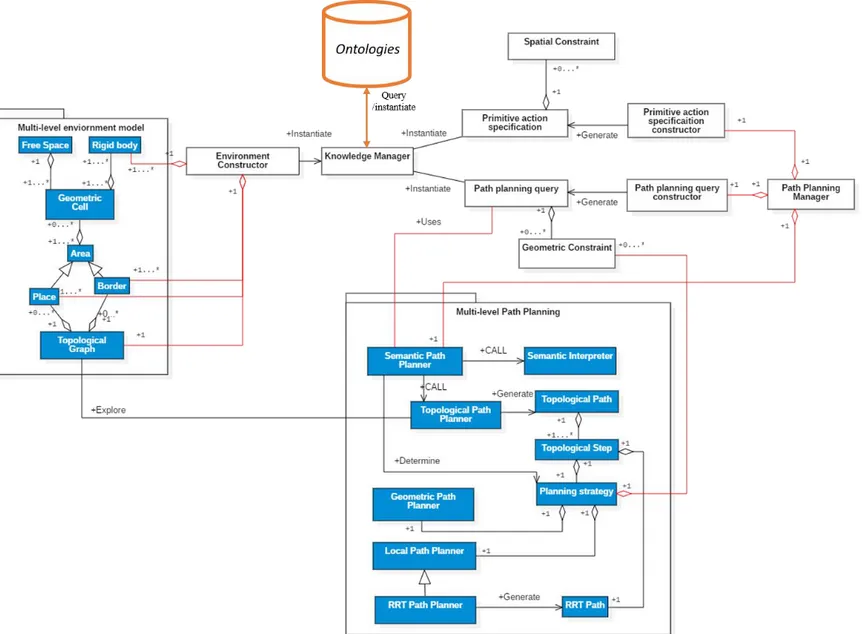
Figure 5 The multi-level path planning... 18
Figure 6 The joint usage of task and path planning ... 19
Figure 7 Placement Constraint [Bidot et al. 2017] ... 28
Figure 8 A taxonomy of geometric constraints [Perzylo et al. 2015] ... 36
Figure 9 The assembly task between two objects [Perzylo et al. 2015] ... 36
Figure 10 Contributions ... 40
Figure 11 The general architecture of the ontology of 3D environment ... 47
Figure 12 The basic mathematical concepts for the geometric description ... 49
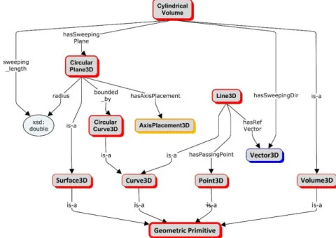
Figure 13 The representation of geometric primitives ... 52
Figure 14 The representation of supplementary geometric primitives ... 53
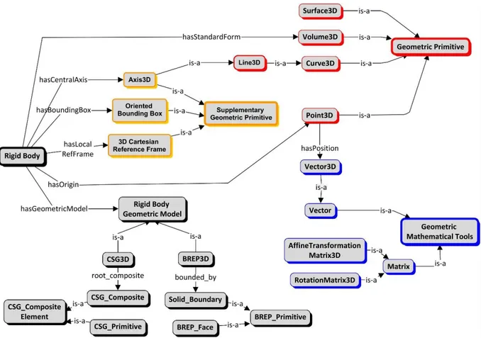
Figure 15 The geometric representation for the rigid bodies model ... 56
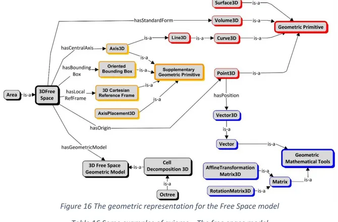
Figure 16 The geometric representation for the Free Space model ... 58
Figure 17 The topological description module ... 59
Figure 18 The semantic description module ... 61
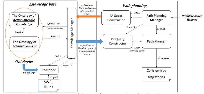
Figure 19 The general architecture of the proposed ontology-based approach ... 70
Figure 20 The conceptual map of the ontology of action-specific knowledge ... 71
Figure 21 The instantiation of the simulation environment ... 73
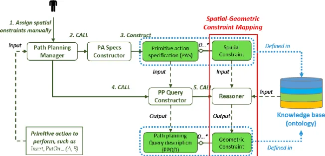
Figure 22 The process to construct a PAS and to generate a related PPQD ... 74
Figure 23 Interfacing with the multi-level path planning architecture ... 74
Figure 24 The domain UML class diagram of the ontology-based approach towards coupling task and path planning ... 81
Figure 25 The environment instantiation in the knowledge base ... 82
Figure 26 The construction of a primitive action specification ... 83
Figure 27 The generation of the path planning query of a primitive action ... 83
Figure 28 The multi-level path planning process with a parameterized path planning query ... 84
Figure 29 A pen-penbox insertion use case ... 85
Figure 30 An instantiation of a pen in the environment model knowledge ... 86
Figure 31 The construction of a primitive action specification ... 86
Figure 32 The generation of a path planning query description ... 88
Figure 33 A graphical representation of the SWRL rule ... 89
Figure 34 Environment Construction: a) Initial Environment b) Cell decomposition c) Places and Borders ... 89
Figure 35 Multi-level path planning: d) Topological Path e) Initial, Final and Border Configuration f) the generated collision-free geometric path (RRT Path) ... 90
Figure 36 Virtools Interface ... 94
Figure 37 The script for defining the behavior using BB ... 95
Figure 38 The graphical Interface of Protégé ... 96
Figure 40 The asserted/inferred classes of an ontology ... 97
Figure 41 The bidirectional RRT algorithm [Cailhol 2015] ... 99
Figure 42 Path planning using GT strategy [Cailhol 2015] ... 99
Figure 43 The topological path construction using GTS strategy [Cailhol 2015] ... 101
Figure 44 The application of geometric constraints in GO strategy... 102
Figure 45 The application of geometric constraints in GO strategy... 103
Figure 46 The architecture of the path planning system ... 104
Figure 47 Environment Construction and Instantiation ... 105
Figure 48 Primitive action specification ... 105
Figure 49 The path planning for a primitive action ... 106
Figure 50 A pen-penbox insertion use case ... 106
Figure 51 Shape Embedding Game ... 107
Figure 52 Instantiated Ontology for 3D Environment of the Pen-penbox insertion scenario ... 109
Figure 53 SPARQL Query Result - Pen1 ... 110
Figure 54 The condition of whether Pen1 can be inserted into P2 ... 111
Figure 55 SPARQL Query - – The possibility of inserting a pen into a penbox ... 112
Figure 56 The search of goal to reach: ‘pen_goal’ ... 113
Figure 57 Path planning results for 'Insert (Pen1, Penbox1)' ... 114
Figure 58 The computed path using 'G, GT, GTO, GO, GTS' Strategies ... 114
Figure 59 Instantiated Ontology for 3D Environment of the Shape Embedding Game Scenario ... 117
Figure 60 SPARQL Query Result - O3 ... 119
Figure 61 SPARQL Query Result - P5 ... 119
Figure 62 SPARQL Query - – The possibility of inserting O3 into P5 (derivation 2) ... 120
Figure 63 The search of goal to reach: ‘O3_Goal’ ... 121
Figure 64 The shape alignment for O3 and P5 ... 122
Figure 65 Path planning results (G, GT, GTS, GO, GTO): Number of random sample used ... 124
Figure 66 Path planning results (G, GT, GTS, GO, GTO): Total Computational Time ... 124
Figure 67 The computed path using 'G, GT, GTO, GO, GTS' Strategies ... 125
Figure 68 The extension of the border with different coefficient ... 126
Figure 69 Path planning results (the GTO Strategy with different BEC) ... 126
Figure 70 The visual representation of a geometric constraint 'Vector1 Against Vector2' ... 147
Figure 71 The graphical representation of the pattern 1 ... 148
Figure 72 The possible orientations of Pen1 (Sample1, Sample2) ... 150
Figure 73 The shape alignment for O3 and P5 ... 151
Figure 74 Geometric Constraint 2 ... 152
List of tables
Table 1 The basic concept of task planning ... 11
Table 2 The task planning strategies ... 12
Table 3 The categorizations of path planning works [Cailhol 2015] ... 13
Table 4 The planning strategies of the classical joint task and path planning ... 20
Table 5 The modeling of rigid bodies ... 25
Table 6 The modeling of the free space ... 26
Table 7 Some commonly used relations in the semantic network ... 30
Table 8 Some commonly used relations in the ontology ... 32
Table 9 The ontology models for conceptualizing environment information ... 34
Table 10 Competency Questions ... 45
Table 11 Basic Concepts in Ontology ... 48
Table 12 Axioms – Basic mathematical concepts ... 50
Table 13 Some examples of axioms – Geometric Primitives ... 52
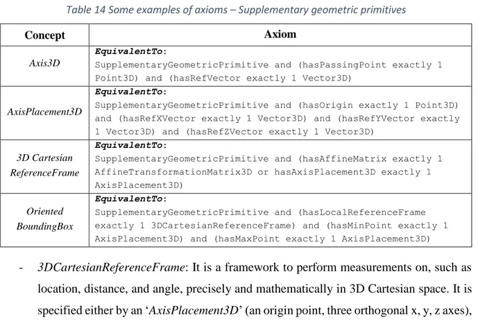
Table 14 Some examples of axioms – Supplementary geometric primitives ... 53
Table 15 Some examples of axioms – The rigid bodies model ... 56
Table 16 Some examples of axioms – The free space model ... 58
Table 17 Some examples of axioms – The topological description module ... 59
Table 18 Some examples of axioms – The semantic description module ... 62
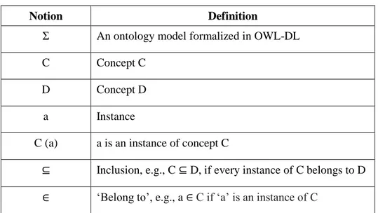
Table 19 Some necessary notions ... 66
Table 20 Symbols for the atom definition ... 68
Table 21 Typical Atoms in SWRL ... 68
Table 22 Competency Questions - Querying geometric details ... 110
Table 23 Competency Question – The possibility of inserting Pen1 into Penbox1 ... 111
Table 24 The primitive action specification ... 112
Table 25 The corresponding path planning query ... 113
Table 26 Competency Question - Query geometric details ... 118
Table 27 Competency Question - Query geometric details (P5) ... 118
Table 28 Competency Question – The possibility of inserting the triangular prism pen into P5 ... 120
Table 29 The primitive action specification ... 121
Acronymes
2D 2-Dimension. 3D 3-Dimension. BB Building Block BG Behavioral Graph
B-Rep Boundary Representation B-spline Basic Spline CAD Computer-aided Design CSG Constructive Solid Geometry CSP Constraint Satisfaction Problem DL Description Logics
FCL Flexible Collision Library FF Fast-Forward
G Geometry
GO Geometry and Ontology GT Geometry and Topology
GTO Geometry, Topology and Ontology GTS Geometry, Topology and Semantics HTN Hierarchical Task Network
IRI Internationalized Resource Identifier LGP Laboratoire Génie de Production NURBS Non-uniform rational B-spline
OMRKF Ontology-based multi-layered robot knowledge framework OOP Object-oriented programming
OWL Web Ontology Language
OWLAPI Web Ontology Language – Application Protocol Interface PA Primitive action
PAS Primitive action Specification
PDDL Planning Domain Description Language PLM Product Lifecycle Management
PP Path planning
PPQD Path planning query description PRM Probabilistic roadmap
RRT Rapid exploring random tree
SIFT Scale-invariant feature transform
SPARQL SPARQL Protocol and RDF Query Language STEP STandard for Exchange of Product model data SWRL Semantic Web Rule Language
Chapter 1 General Introduction
The increasingly competitive market and economic competition pushes harder and harder on industrial companies to reduce the time and the cost of new product development, whereas the up-to-date industrial products become more complex and integrated. Industry companies express the strong need to validate, from the design stage on, not only the static models of their products but also all tasks related to their Product Lifecycle Management (PLM). With the help of digital prototypes (e.g., Computer-aided design models), complex industrial operations under strong geometric constraints (e.g., assembly, disassembly or maintenance) can be simulated and validated before entering into the real product manufacturing. The abnormalities of the product design can be earlier detected before building physical prototypes.
In this dissertation, we are particularly interested in simulating and validating manipulation tasks under strong geometric constraints. The scientific community looked at this issue from two points of view:
- task planning decomposes a manipulation task to be realized into a feasible sequence of primitive actions (i.e., a task plan);
- path planning demonstrates the feasibility of manipulations by computing collision-free trajectories, notably for the manipulated objects. It traditionally uses purely geometric data, which leads to classical limitations (possibly high processing time, low path relevance regarding the task to be performed, or failure)
Task planning cannot verify the motion feasibility (i.e., finding feasible trajectories) of primitive actions of a task plan and path planning does not allow to reason at the task level. Therefore, solving a complex manipulation task requires to consider task planning and path planning jointly. Joint task and path planning approaches found in the literature usually perform a classical task planning step and check out the feasibility of path planning requests associated with the primitive actions of this task plan. However, the link between task planning and path planning has to be improved, notably because of the lack of loopback between task planning level and path planning level:
- path planning queries associated with primitive actions of a task plan traditionally use purely geometric data; the task level information has not yet been considered at the path planning level;
- the path planning related information used to question a task plan is usually limited to the motion feasibility of primitive actions of the task plan; richer path planning information would be needed to compute an optimal task plan, such as the relevance or the complexity of the proposed path.
This thesis work focuses on path planning for a primitive action of a task plan. It is motivated by the idea that using task-related information at the path planning level can lead to better path planning results (i.e., lower processing time, better path relevance regarding the task to be performed). Therefore, better simulations for the assistance of manipulations can be obtained. In order to generate a path planning query for a primitive action of a task plan, different kinds of task-related information should be considered:
- The environment information of a manipulation task to be performed: This information allows us to determine the start and the goal location of the path planning query. - The information associated to a primitive action to be performed, for example, the
spatial constraints given by a user restricting relative location between two objects involved in the primitive action: This information further allows us to determine the geometric constraints (associated to the path planning query) that restricts the movement of a manipulation object.
Indeed, the idea of using task-related information at the path planning level is difficult to be implemented, because the modeling of task-related information varies from one application to another. In order to build a path planning system capable of dealing with different applications, it is necessary to have an evolvable knowledge model of task-related information. Different levels of abstraction should be considered. Domain-independent information is commonly shared among applications, whereas application-specific information is updated regarding the task to be performed. Moreover, using such a knowledge model, the path planning system should be able to infer new information so that a relevant path planning query can be generated for a primitive action, e.g., such as finding the right goal location to reach.
This requirement drives us to explore the knowledge modeling tools in the literature. We choose ontology as our knowledge modeling tool in this dissertation, because of its knowledge querying and reasoning capability. Moreover, ontologies allow separating information at different levels of abstraction by constructing modules.
In this dissertation, we propose an ontology-based approach to use task level information to specify path planning queries for the primitive actions of a task plan. The work presented consists of three main parts:
- We propose an ontology to conceptualize the knowledge about the 3D environment in which the simulated task takes place. The environment is represented by a digital model relying on a multilayer architecture involving semantic, topologic and geometric data. The originality of this ontology lies in the fact that it conceptualizes heterogeneous knowledge about both the obstacles and the free space models.
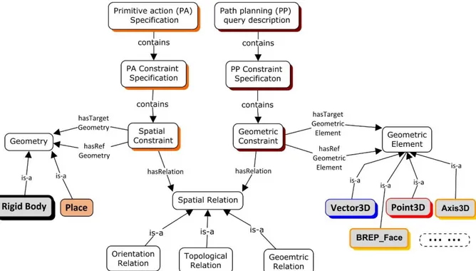
- We propose an ontology of action-specific knowledge. It models the spatial constraints to be taken into account in the specification of a primitive action and the geometric constraints to be obeyed in the description of a path planning query. Their definitions rely on the ontology of the 3D environment in which the simulation takes place. - We propose an ontology-based method to generate a path planning query for a primitive
action of a task plan. Through a reasoning process involving a primitive action instantiated in the ontology of action-specific knowledge, we are able to infer the start and the goal configurations, as well as task-related geometric constraints by exploring an instantiated ontology of 3D environment.
The contributions of this thesis work will be validated by full simulations of several manipulation tasks under strong geometric constraints. The path planning results will be compared. The thesis work is organized in the following chapters:
In Chapter 2, we will introduce the industrial and the scientific context of this thesis work. We focus on simulating and validating manipulation tasks under strong geometric constraints (i.e., assembly, disassembly and maintenance). The scientific community discussed this issue from the task planning point of view and the path planning point of view. When task planning and path planning are used jointly, the link between them still has to be improved, notably because of the lack of loopback between them. This thesis work particularly focuses on using task-related information at the path planning level. Although different kinds of task-task-related information can be found at the task level, they usually rely on the task to be solved, and they cannot be easily reused or updated from one application to another. In the meanwhile, ontology, as a knowledge modeling tool, allows to build a modular and evolvable knowledge model. Therefore, building ontologies of task-related information draws our attention. In our research, we presented an ontology-based approach to use task-related information to specify a path planning query of a primitive action of a task plan.
Chapter 3 gives a detailed description of an ontology of 3D environment where a simulated manipulation task takes place. A waterfall-like engineering method is applied. In this chapter, we discuss why different levels of environment information should be considered (i.e., semantics, topology and geometry) jointly. We apply a modular architecture in the proposed ontology. We can easily see that a concept might have different meanings at different levels. Chapter 4 discusses an ontology-based method to generate a path planning query for a primitive action of a task plan. Firstly, an ontology of action-specific knowledge is proposed. This ontology is modeled based on the ontology of 3D environment (Chapter 3). Through a reasoning process involving a primitive action instantiated in the ontology of action-specific knowledge, we demonstrate how a corresponding path planning query is generated. In particular, we show how geometric constraints are inferred from spatial constraints.
Chapter 5 performs ontology validation and simulation experiment for the contributions proposed in Chapter 3 and Chapter 4. The path planning strategies to be compared are introduced at the beginning of this chapter. Then, two simulation scenarios are presented. In the end of this chapter, the evaluation on each of the two scenarios are presented and discussed. In Chapter 6, we make a synthesis of our proposed contributionsin section 6.1. Section 6.2 discusses the benefits of our proposed ontology-based approach to use task-related informatin in the path planning of a primitive action. After we have discussed the benefits, we also present the analysis of the limitation of the proposed approach. At the end of this chapter, we will discuss several key perspectives in which we might interest in the future.
Chapter 2 Motivation and Context of the work
This chapter describes the motivation and the context of our work. The first part (section 2.1) points out the industrial context at which this work is targeted. Facing the economic competition, PLM has been applied in the industrial production to reduce the time and the cost of the product development (section 2.1.1). Virtual prototypes have been used along with the V-Cycle model of PLM to pre-validate the design of industrial products. Simulations performed on virtual prototypes allow to validate industrial operations under strong geometric constraints (i.e., assembly, disassembly, maintenance) before real product manufacturing (section 2.1.2). The recently emerged VR technique provides the user a great realism and the capability of interacting with simulations so that industrial operations can be better verified (section 2.1.3). The second part (section 2.2) illustrates the concentration of this thesis work on simulating and validating manipulation tasks under strong geometric constraints (assembly, disassembly, and maintenance). This issue begins with a discussion of task planning (section 2.2.1) and path planning (section 2.2.2). Solving a complex manipulation task requires to consider them jointly. However, the loopback between task planning and path planning remains poor (section 2.2.3). In this thesis work, we are interested in using task-related information at the path planning level. The modeling of task-related information is discussed (section 2.2.4) and the necessity of building a knowledge model of task-related information is expressed (section 2.2.5). In order to properly generate a path planning query of a primitive action, action-specific knowledge should also be carefully considered (section 2.2.6). Section 2.2.7 analyzes the locks of these works, introduces the positioning of our work and discusses the challenges. In the final section (section 2.3), the principle ideas and contributions of our work are presented.
2.1 INDUSTRIAL CONTEXT
Nowadays, industrial companies are required to reduce the time and the cost of the product development, whereas industrial products become more and more integrated, and quality and normative standards are increasingly demanding. In this context, since the beginning of the 21st century, the Product lifecycle management (PLM) has emerged as a new paradigm, from the design stage on, of managing all aspects (e.g., resource, people, data, method) of a product during its lifecycle.
The information technology has been put into service to manage a product’s data along its lifecycle consistently. In particular, the design of new products has been given foremost support to apply new ideas. Indeed, the process and resource management, collaboration and communication among people or organizations, and project management can also be consolidated using the information technology [Neubert et al. 2004, Sureephong et al. 2008]. Such systematic management of the product data makes it easier to develop, to manufacture, to use and to dispose of a product.
Moreover, in order to take full advantage of what PLM offers, the implementation of PLM has to be adapted into the company’s business process. Recently, the implementations of PLM in the aerospace industry have been reviewed [Cantamessa et al. 2012]. The benefits of using PLM tools have been mainly categorized into three levels:
1) Operational effects and benefits: PLM assists in identifying and reducing ineffective/inefficient/unnecessary activities. It helps the maximum reuse of the past design information (e.g., through comparison for the best match), and then reduces the possibility of the design error and enables the design optimization. It can also help the individual workers better understand the product and the product’s architecture (e.g., through the product’s portfolio).
2) Organizational effects and benefits: PLM enables data transparency and interoperability along a product’s lifecycle. It reduces the information redundancy, integration efforts, and conflicts in the collaboration during the product’s lifecycle. It results in a more rigorous product development process, to reduce the product change impact, to get a higher design quality and to early detect abnormal in the development process.
3) Strategic effects and benefits: PLM aims at assisting a company in achieving its business objectives, through improving the firm’s performance. The improvements include getting a higher innovation level of a product, minimizing the time and cost of the product development process, minimizing the time of a product to the market, and maximizing the satisfaction of the customers.
2.1.1 Industry and Product Lifecycle Management (PLM)
Product lifecycle management is not a particular method or a specific tool. From the product development point of view [Karniel et al. 2011], it is a systematic way to manage all possible information related to a product to be developed. In particular, the collaborative knowledge embedded in collaborative activities of PLM allows to enhance traceability in decision-making
within PLM process [Matta et al. 2011, Matta et al. 2013]. From the business point of view [Javvadi May 2011], PLM is a business process to minimize the development time and cost during the product’s lifecycle, speed up the launch of the product on the market, maximum the product’s value for money and customer’s expectation. Last but not least, from the company’s management point of view [Stark 2015], PLM is an integrated and joint-up product management strategy and a cornerstone of the company’s success.
The traditional product development process in PLM is driven by the customers’ needs to meet their expectation with some targeted functionalities. Each of these needs is carefully analyzed and specified as the basic functions of a product. These basic functions are then defined, developed and validated individually before integrated into the final expected product. It allows the company to adopt a commonly-used and rigorous development lifecycle model during product development, called the V-cycle model [Hirschberg 2000]. The V-Cycle model, initially developed in German [Plögert 1996] and United States [Forsberg et al. 1991] in the late 1980s, gives a rigorous and formal development step description of a product (see Figure 1):
1) Definition and Design: The conceptualization of a product follows a top-down approach. The product’s portfolio is determined, through a list of sequential steps, from the general system description to the detailed function implementation.
2) Test and Integration: The test and integration of a product follow a bottom-up approach. Each unitary function is validated and verified firstly, and it is then integrated into a higher level system module until the whole system is assembled and checked.
Figure 1 V-Cycle Model for the product development process
The increasingly complex products require a large number of tests to verify and to validate their design, their functionalities and their associated development procedures (e.g., assembly).
However, building physical prototypes can be too time and cost consuming to meet the deadline and the budget, and it is sometimes impossible for complex products, e.g., an airplane.
2.1.2 Using virtual prototypes along the PLM
Responding to time and cost constraints of the product development, industrial companies are seeking for a new, higher controllable and low-cost prototyping tool, from the design stage on,
- Not only to validate the static models of their industrial products
- But also to validate all possible tasks associated with their PLM, such as assembly, disassembly, and maintenance.
Answering to these requirements, 3D Computer-Aided Design (CAD) modeling, starting from the mid of the 1960s, uses the power of computers to support the creation, modification, analysis, and optimization of a product using virtual prototypes [Sarcar et al. 2008]. Functional and integration tests performed on virtual prototypes reduce the number of physical models required, and they allow to eliminate abnormities early at a significantly reduced cost. However, these tests are conducted with inaccuracies using the approximate product models. The virtual prototypes may not assist an exclusive validation and verification of products. As a result, the physical prototypes are often interleaved with the virtual prototypes in the V-cycle product development process proposed in Figure 2 [Cailhol 2015]. Virtual prototypes pre-validate a product at its conceptualization stage, and physical models allow the real-world tests before the product is manufactured.
Figure 2 The V-cycle product development process in PLM using numerical and physical models [Cailhol 2015]
Besides foremost support to the design of products (i.e., the static CAD models), virtual prototypes have also been widely used for the simulation purpose. Different simulation software, e.g., DMU kinematics for CATIA® [Systemes 2014], Motion modules for Solidworks®
[Systemes 2014], carries out the kinematic analysis of a system and verifies whether the system can function correctly. Other tools concern the simulation of the assembly or the dismantling of products, and the feasibility of integrating the components of a product can then be verified. However, for a highly integrated product, these tools encounter difficulties of finding the right assembly paths.
2.1.3 PLM with the Virtual Reality (VR) technique
Recently, thanks to the progress made by sensorimotor interfaces and their coupling with 3D content, the emergence of VR techniques allow immersive and interactive task simulations while considering the human operator in the loop. The presence of human operators offers the possibility to modify the scenario interactively, and its immersion in the virtual world allows greater realism of the simulation.
One main VR application is to simulate and to validate the assembly tasks of products at the design stage before entering into real manufacturing and production. We noted that a highly integrated industrial product makes it difficult to perceive geometric constraints and to define reasonable assembly sequences and trajectories respecting user’s immersion in the virtual simulation. These simulations can be then enhanced by tools to assist users.
- The feasible sequence of assembly and disassembly can be automatically generated by identifying the geometric constraints between the virtual assembly parts. These constraints can either be directly extracted from the assembly tree of the CAD software or through analyzing the contacts between the virtual parts. Once they have been identified, visual guidance compliant to the constraints can be provided to users through a haptic device to facilitate the assembly of the components [Tching et al. 2010]. This work progressively uses geometric visual fixtures (i.e., software generated forces and position signals [Abbott et al. 2007]) as guidance until the final assembly position of a component is reached.
- The feasible (possibly collision-free) trajectories for the assembly of virtual parts of a product can be automatically calculated using path planning tools [Ladeveze et al. 2009]. The trajectories are then used to guide users through a ‘haptic force’ until the final location is reached. Once the manipulated object is forced to move away from this trajectory, the user’s manipulations trigger the re-calculation of a new path.
2.1.4 Synthesis
As up-to-date industrial products are more and more integrated and the economic competition increases, industrial companies express the need to validate, from the design stage on, not only the static CAD models of their products but also the tasks (e.g., assembly or maintenance) related to their Product Lifecycle Management (PLM). Virtual prototypes are used along with the V-cycle model of the product development to pre-validate the design and the integration of products at the conceptualization stage, whereas physical prototypes run the real world tests to eliminate the inaccuracies brought by the approximate virtual product models. Simulations running on the virtual prototypes allow further to verify and to validate the tasks associated with PLM, e.g., the assembly of industrial products. The recently emerged VR techniques allow interactive and immersive simulations to provide the involved human operator a great realism and the capability to alter the scene.
The simulations of complex tasks related to PLM possibly under strong geometric constraints, i.e., assembly and maintenance, check the behaviors of products and their associated parts during assembly. The abnormalities of the design of products can be early and better detected. The simulations also possibly provide the manipulation assistance to the involved users, so that the inexperienced users can be better trained.
2.2 STATE OF THE ART: MANIPULATION TASK SIMULATION
This thesis work deals with the simulation and the validation of complex manipulation tasks under strong geometric constraints (i.e., assembly, disassembly and maintenance) in virtual environments. The scientific community looked at this issue from two points of view.
- Task planning, reasoning at the task level, decomposes a manipulation task to be realized into a sequence of primitive actions (i.e., a task plan)
- Path planning computes collision-free trajectories, notably for the manipulated objects. It traditionally uses purely geometric data, which leads to the classical limitations (i.e., high processing time, low path relevance regarding the task to be performed or failure). Joint task and path planning approaches perform a classical task planning step and checks out the feasibility of path planning requests associated with primitive actions of a task plan. However, the link between task planning level and path planning level has to be improved because there lacks loopback between these two levels:
- Path planning queries of primitive actions of a task plan use purely geometric data; no task-related information has been considered to control the path planning process.
- The path planning information used to question a task plan is usually limited to the motion feasibility of primitive actions of the task plan; richer path planning information would be needed, such as the relevance or the complexity of the proposed path.
This thesis work focuses on using task-related information to control the path planning for a primitive action of a task plan. Different modalities of task-related information should be considered; the method of using task-related information in the path planning process of a primitive action should be discussed.
The following sub-sections start with discussing the related work of task planning (section 2.2.1) and path planning (section 2.2.2), following the necessity to consider them jointly in solving a complex manipulation task (section 2.2.3). Section 2.2.4 explores the modeling of task-related information. Section 2.2.5 discusses the necessity of building a knowledge model of task-related information. Moreover, in order to properly generate a path planning query for a primitive action, task-related information should also take action-specific knowledge into consideration (section 2.2.6). In the end, through analyzing the state of the art concerning manipulation task simulations, their locks are identified, the objectives of this thesis work are specified and the corresponding challenges are listed (section 2.2.7).
2.2.1 Task planning
One issue of simulating complex manipulation tasks is to find a feasible sequence of primitive actions, e.g., to re-arrange the objects to be manipulated. Such an issue belongs to the task planning problem, which generally considered as symbolic planning in the artificial intelligence domain [Russell et al. 2003]. Task planning maintains a symbolic representation of the environment where the simulated task performs. In such a representation, objects and locations are categorized regarding the task context, such as objects like ‘Book’, ‘Table’, locations like ‘Office’, ‘Corridor’. Some basic concepts of task planning are given in Table 1 before discussing different task planning strategies.
Table 1 The basic concept of task planning
Concept Definition
Relations A list of predicates describing how two or more things are related to each other. For example, On (x, y) defines a relation that x is on y, where x and y are variables.
Environment State
A list of propositions describing the state of an environment [Bidot et al. 2017], e.g., where objects are, how they are related to each other, what is the state of a location, such as In (CoffeeMachine, Office), On (Book, Table), OnFire (Office). A proposition sometimes can be considered as a relation with grounded values. Initial State Initial State: The state that an environment initially holds
Goal State Goal State: The state that an environment must reach
Primitive action
A primitive action manipulates the state transition. It describes how a state changes when it is applied [Tzafestas 2013]. It is propositionally defined by preconditions and effects [Srivastava et al. 2014].
- Precondition: A list of propositions that an environment state must hold to trigger the primitive action
- Effect: A list of propositions, to which an environment state will transit, after the execution of the primitive action.
State Space The set of all states reachable from the initial state by a sequence of primitive actions [Russell et al. 2003]
2.2.1.1 Task planning strategies
The objective of task planning is to find a feasible sequence of primitive actions (a task plan) to reach a given goal environment state. Different planning strategies can be found in the literature, as shown in Table 2.
Table 2 The task planning strategies
Planning strategies Description
The state-action approaches
Forward-searching
Starting from a given initial state, this strategy progressively explores applicable primitive actions until the goal state is reached. It can either search the entire state space until it finds a feasible path (i.e. breath-first algorithm [Giunchiglia et al. 1999]) or uses heuristic-based functions to get an optimal task plan [Bonet et al. 1999].
Backward-searching
Starting from a given goal state, this strategy recursively decomposes goal into a list of sub-goals until it solves conflicts and holds the initial states. [Kaelbling et al. 2011]
Hierarchical task network (HTN)
Unlike classical “goals-to-be” or “state of the world” approaches, the HTN approaches focuses on solving “abstract tasks” or “goals-to-do” [Nau et al. 2003, Kemke et al. 2006, de Silva et al. 2013].
It maintains a finite set of methods (M) and a finite set of primitive tasks (PTs). We note that the definition of PT is equivalent to the definition of primitive action. Each method (m) has
- a name (name)
- an abstract task (abtask) that it is used to solve
- a sequence of sub-tasks (subtask) to solve the abstract task (a sub-task is either an abstract task or a primitive task)
- a list of constraints to be obeyed (constraints)
Given a sequence of (primitive or abstract) tasks (d) to be solved, the HTN planning process recursively searches for the applicable methods in M until d contains only primitive tasks (PTs).
Currently, we focus on classical state-action approaches. Figure 3 presented an example of re-arranging object A, B, C on the table [Tzafestas 2013]. The initial state of the environment (Figure 3-A) is “On (C, Table), On (B, Table), On (A, C)”, and the goal state to reach (Figure
3-B) is “On (A, Table), On (B, A), On (C, B)”. A feasible sequence of actions to re-arrange them is “unstack (A, C), put_down (A), pick_up (B), stack (B, A), pick_up (C), stack (C, B)”
Figure 3 An example of task planning
2.2.1.2 Synthesis
However, task planning alone cannot geometrically verify and implement primitive actions of a task plan. It assumes that all primitive actions can be performed if an environment state satisfies their pre-conditions. For example, a ‘pick_up’ action can be performed if a robot’s hand is free. However, the geometric motions of this action may be not realizable due to the obstacles between the robot and the targeted object.
2.2.2 Path planning
Another issue of simulating complex manipulation tasks is to generate and to validate motions for the manipulated objects. This issue has already been discussed by the robotics community since 1980, as a path planning problem [LaValle 2006]. It computes a collision-free trajectory, notably for a manipulated object, to demonstrate the feasibility of the manipulation.
2.2.2.1 Automated path planning strategies
Until now, the solutions for path planning problems appear as a technical library book [Choset et al. 2005]. [Cailhol et al. 2015] categorizes them, regarding whether a global environment model is built (global and local approaches) and how the path is constructed (deterministic and probabilistic methods), into the four-quadrants.
Table 3 The categorizations of path planning works [Cailhol 2015]
Global approach Local approach
Deterministic methods Cell decomposition
Roadmap Potential field
Probabilistic methods Probabilistic roadmap RRT
We will now see the most representative works in each quadrant in Table 3.
- Cell decomposition: This technique decomposes an environment into elementary geometric cells. A cell is classified as free or occupied, depending on whether this cell is occupied by obstacles. The connectivity of free cells may be used in the path search. Different kinds of works can be found in this group, according to how the cells are formed, such as Regular cell decomposition [Samet 1984], Octree/Quadtree [Meagher 1982], Triangular decomposition [Brooks et al. 1982].
- Roadmap: This technique uses samples of interest of an environment and their interconnectivity to synthesize an environment’s connectivity in a graph. The Voronoï diagram [Voronoi 1908] construct the graph with the maximum distance to environmental obstacles. The visibility graph [Alt et al. 1988] follows a way how a human sees things in an environment. It connects all the peaks of obstacles and remains those who do not intersect with obstacles.
2) The global approach with the probabilistic method: The techniques in this quadrant obtain random samples of an environment and uses their interconnectivity to construct a global environment model as a connected graph. Then this graph guides the search for collision-free paths. The probabilistic roadmap (PRM) [Kavraki et al. 1996] is the most well-known method, and it aims at solving high-dimensional path planning problems.
3) The local approach with the deterministic method: The techniques in this quadrant search for a collision-free path progressively and deterministically. The potential field method [Khatib 1986] computes an artificial potential for a robot, depending on the robot’s location. The potential is a superposition of the attractive field of the objective G (low potential) and repellent fields of obstacles (high potential). The robot follows the maximum gradient of the potentials to reach G. In a static and known environment, the gradient in any position is deterministic.
4) The local approach with the probabilistic method: The techniques in this quadrant search for a collision-free path progressively using random samples. Rapid exploring random tree (RRT) method [LaValle 1998] has been proposed to deal with high-dimensional planning problem in a complex, possibly unknown or dynamic environment. It progressively explores the environment by placing random samples until a valid path can be found between the start and the goal configuration.
However, these path planning techniques heavily rely on their geometric models and use purely geometric data. In a highly geometrically constrained manipulation environment, they may fail,
consume a large computational time or generate a path with little relevance regarding the task to be performed (i.e., classical limitations of path planning techniques).
2.2.2.2 The use of high abstraction level environment information
A human operator often performs a manipulation task more relevantly and finds solutions in a reasonable time. This is due to his cognitive capability and trade-oriented knowledge [Cailhol et al. 2019]. The human’s understanding of an environment and of objects are not limited to their geometric models but include higher abstraction level environment information, such as their topological properties and their semantics possibly related to a task to be performed (e.g., complexity). Research works of the robotic localization and navigation in an indoor environment [Hu et al. 2004, Tsetsos et al. 2006, Galindo et al. 2008, Bastianelli et al. 2013] has explored the interest of using different natures of environment data (i.e., semantics, topology, geometry) for path planning. In the meanwhile, our research work focuses on manipulation task simulations. Fewer works in this domain have discussed the benefits of using high abstraction level environment information for path planning. Two main kinds can be found in the literature.
A. The semantic 3D object map
[Rusu 2010] presented a semantic 3D object map to annotate environment objects and their surfaces with semantic labels. It consists of a 3D point cloud perceived from robot perception (e.g., vision [Dandois et al. 2013], touch [Vásquez et al. 2017]), polygonal models of objects constructed from clustering and segmentation of the point cloud, and a semantic interpretation of objects and their surfaces. It serves as semantic resources to determine the final grasp or placement position for a manipulation. For example, in an indoor kitchen environment, it allows a robot to locate the hinge of a drawer when a robot is given a high-level command to open the drawer. In the meanwhile, [Tenorth et al. 2010] presented a richer semantic description of environment objects, called ‘Knowrob-Map’, by using knowledge from different resources, such as encyclopedic knowledge, common-sense knowledge, and action-related knowledge. However, the modeling of semantic data is limited to the indoor household environment. Except for finding the goal location, the semantic information of this map has not yet been considered to control the path planning process, e.g., to restrict the pose of a manipulated object.
B. The multi-level environment modeling and path planning
Recently, researchers from LGP proposed a multi-level environment modeling and path planning architecture [Cailhol et al. 2015] to consider higher abstraction level information (i.e.,
semantics and topology) rather than purely geometric data traditionally used in simulating manipulation tasks. It consists of a multi-level environment model and a two-step path planning strategy.
1) Multi-level environment model
The 3D simulation environment for a manipulation task is considered as a closed part of 3D Cartesian space cluttered with static or mobile obstacles considered as rigid bodies. The proposed model consists of a free space model and a rigid body model, as illustrated in Figure 4.
Figure 4 The multi-level environment model [Cailhol et al. 2015] A rigid bodies model
- Geometric layer: The geometry of a rigid bodies model is represented by a classical polygonal model (i.e., vertices, edges and faces from Delaunay triangulated mesh). It is represented by a single class ‘Rigid Body’ in the class diagram (Figure 4).
- Semantic layer: The semantics of a rigid bodies model consists of attributes attached to rigid bodies (see the association link between ‘Rigid body’ and ‘Semantic Information’ in Figure 4-a). The form of a rigid body is specified by a shape attribute. The mobility attribute defines whether a rigid body is movable or fixed.
- Geometric layer: The geometry of a free space model is described using a cell decomposition based on Octree (Figure 4-d). Each cell is marked as free, intersected or blocked depending on whether or how it intersects with rigid bodies.
- Topological layer: The topology of a free space model uses a topological graph to describe the connectivity between places and borders (Figure 4-c). A Place is noted as P (x), and a Border is noted as B (x, y). In the topological graph, a node represents a border and an edge corresponds to a place. Geometrically, places and borders consist of a collection of free cells (see the association link between ‘Area’ and ‘Geometric Cells’ in Figure 4-a).
- Semantic layer: The semantics of a free space model is made of attributes attached to places and borders (Figure 4-b). For example, the complexity attached to a place describes the difficulty of crossing this place. The existence of mobile obstacles implies the cluttering of a place.
2) Two-step path planning strategy
A two-step path planning strategy is used along with the proposed multi-level environment model [Cailhol et al. 2019], as in Figure 5.
- A coarse planning process computes a Topological Path on the Topological Graph (Figure 5-a). It consists of Topological Steps. Each step consists of a place to across (e.g., P1) and a border to reach (e.g., B (1,5)). The choice of which place to across relies on the semantic attributes attached to places and the manipulated rigid body (e.g., the complexity of a place).
- A fine planning process aims at refining each Topological Step into a concrete geometric trajectory to guide the movement of the manipulated Rigid Body. Depending on the complexity of a place, different local path planning strategies can be used. For example, a direct link between the current location of the manipulated Rigid Body and the milestone to reach is used when the place is free, whereas RRT method is preferred when it is narrow or congested.
Figure 5 The multi-level path planning
This work uses a case study inspired from a ‘shaped game’ for babies. The experimental results have demonstrated that, using higher abstraction level information (i.e., semantics and topology), the path planning results have been improved comparing to the state of the art automated path planning techniques.
- From the qualitative aspect: The computed path is of higher relevance, thanks to the semantic information attached to places and rigid bodies.
- From the quantitative aspect: The number of needed random samples to define a trajectory is largely reduced by restricting the search space to the targeted places and using the semantic control to avoid the narrow and complex regions. Thus, it results in less processing time for path computation.
However, its semantic model is still preliminary with no task-related information considered. The semantic and topologic data have not yet taken into account in the geometric path computation. The RRT algorithm used in narrow places still suffers the classical limitation of automated path planning techniques.
2.2.2.3 Synthesis
A key issue of simulating manipulation tasks is to find collision-free trajectories for manipulated objects to demonstrate the feasibility of manipulations. We begin the discussion by reviewing the related works of automated path planning techniques. These works traditionally use purely geometric data and they encounter classical limitations. Using higher
abstraction level environment information (e.g., semantics, topology) rather than purely geometric data in path planning can possibly lead to better path planning results. In the domain of manipulation task simulations in which we are interested, two main kinds of works have been presented. Although they have demonstrated the benefits of using high abstraction level environment information (e.g., semantics, topology) in path planning, they provide limited control on the path planning process and task-related information has not yet been fully considered. Moreover, path planning cannot reason at the task level to find a feasible task plan.
2.2.3 The joint usage of task planning and path planning
Solving a complex manipulation task problem requires to consider task planning and path planning jointly [Siméon et al. 2004]. The common type of joint task and path planning approaches consists of two significant processes [Lagriffoul et al. 2014], as shown in Figure 6: - At the task planning level, a task planner decomposes a manipulation task to be realized into a feasible sequence of primitive actions (i.e., a task plan) so that a goal state, e.g., where objects A, B, C are arranged properly, can be reached.
- At the path planning level, a geometric path planner checks out the feasibility of path planning requests associated with primitive actions of a task plan. Once a primitive action is found geometrically infeasible, the path planner informs the task planner to find an alternative task plan.
Therefore, the search space of joint task and path planning [Lagriffoul et al. 2016] is the cross product of the state space (task planning) and the configuration space (path planning).
2.2.3.1 Planning strategy
There exist in the literature different joint task and path planning techniques from the robotic domain allowing to solve complex task problems. In terms of when the geometric feasibility of a primitive action in the task plan is verified, we category these techniques in two main classes (
Table 4).
Table 4 The planning strategies of the classical joint task and path planning
Planning strategy Definition
Task planning, then path planning,
iteratively
The key point of this planning strategy is that the feasibility of primitive actions of a task plan is verified after the complete task plan is constructed.
- If all primitive actions of a task plan are geometrically feasible, the task plan is verified.
- Otherwise, the logical constraints representing the failures will be added into the task planning problem description and then the task planner looks for an alternative task plan.
Using path planning during
task planning
The key point of this planning strategy is that the feasibility of primitive actions of a task plan is verified during the construction of a task plan.
At each leaf candidate state of the search tree, the feasibility of each applicable candidate primitive action is instantly verified by a path planner.
- If the candidate primitive action under verification is feasible, the corresponding branch will be further explored.
- Otherwise, the corresponding branch will be abandoned.
1) Task planning, then path planning, iteratively
Different research works implement their own task and path planning process. [Erdem et al. 2011] proposed to invokes a RRT path planner to compute continuous trajectories for a robot once a task plan is constructed. [Dearden et al. 2013] discussed a probability model, built from a learning process, to generate the valid geometric pose of manipulated objects or of the robot for the symbolic states involved in a generated task plan. The geometric description is then used to compute the continuous trajectory for the robot. More recently, [Srivastava et al. 2014] proposed to use arbitrary off-the-shelf task planners (e.g., CCALC [McCain et al. 1997]) instead of developing a new variation. The approach addresses the problem of continuous refinement of an initial task plan by correcting inaccurate task description with constraints gained from geometric reasoning (path planning). Once an initial task plan is generated, the task plan is progressively refined from where the failure occurs (i.e., no feasible trajectory for a primitive action). The process continues until a geometrically feasible task plan is found or the resource
![Figure 2 The V-cycle product development process in PLM using numerical and physical models [Cailhol 2015]](https://thumb-eu.123doks.com/thumbv2/123doknet/2953977.80624/24.892.120.785.753.1004/figure-product-development-process-numerical-physical-models-cailhol.webp)