Reduced span spray – Part 2: Drift
By S OULED TALEB SALAH1,2, N DE COCK1, M MASSINON1, and F LEBEAU1 1Biosystems Engineering, Gembloux Agro-Bio Tech (GxABT) - University of Liege (ULg), Gembloux, Belgium 2AgricultureIsLife, Gembloux Agro-Bio Tech (GxABT) - University of Liege (ULg), Gembloux, Belgium Corresponding Author Email: [email protected] Summary
Treatment efficiency is drastically affected by the amount of spray drift away the target area. The present study investigates the effect of a reduced span on spray drift based on wind tunnel measurements with the final aim of guiding the design of a reduced span nozzle (Reduced span spray – Part 3: Design of narrow span nozzle). A capillary jet with a free and a forced break up regimes, corresponding to 0.5 and 0.06 span values respectively, was tested under 2 m/s downwind speed. Droplets spots from the free break up regime show a bimodal distribution, which are related to droplets sizes: Bigger droplet travel less distance than smaller droplets. Droplet diameters measured on ground level at different distances from the generator were corroborated with the observed droplets spots. However, deposits from forced break up regime were similar to deposits obtained by the free break up regime, what may be due to emerged drops throughout the droplet stream. Much focus on the forced break up regime is needed to relate droplet size to spray drift.
Keywords: capillary jet, spray drift, reduced span factor, free break up regime, forced break up
Introduction
Spray application efficiency of Plant Protection Products (PPP) is affected by the amount of spray drift away from the target area. Spray drift is influenced by several parameters such as spray characteristics, liquid physico-chemical properties, wind characteristics and nozzle type (Nuyttens and al., 2010).
Decades of technical developments in the crop protection field have led to different nozzles designs producing various droplet size distributions. The uniformity of the produced spray is assessed by a uniformity index, namely span factor calculated as
span=DV90 − DV10 DV50
where DV10, DV50 and DV90 indicates that 10%, 50% and 90% of the spray volume is composed of drops whose diameters are smaller than this value (µm) (Matthews, 1992). Indeed, hydraulic nozzles, which are among the most used techniques, produce a wide droplet size distribution corroborated by a higher span value around 1 (Matthews, 1992; Qi et al., 2008). When the produced sprays are characterized with a low volume median diameter, the proportion of finer droplets within the spray is high, what may induce a high drift level since these finer droplets are travelling beyond the treatment zone. On this basis, an attempt to reduce spray drift was adopted through increasing the proportion of bigger droplets to ensure a more predictable trajectory by developing low drift or air induction nozzles. However, sprays with higher span values were seen detrimental to spray retention as bigger droplets
have tendency to splash on surface target as a function their energy impact (Massinon and al., 2015).
On the hand, much effort is focused on reducing span value by developing Controlled droplet Application (CDA) techniques. The CDA was proved an efficient tool to reduce span values around 0.5 and to control droplet trajectories (Qi et al., 2008). However, CDA was known to produce more drift as expected due to the sensibility of emitted spray to air flow (Qi et al., 2008). On this basis, some techniques aimed at minimizing spray sensibility to air flow were adopted such as shields (Ozkan et al., 1997) and air assistance.
Spray drift has been the subject of extensive investigation. However, few sprays with low span tested for drift are available on the literature. The objective of the present study is to assess the drift potential of a capillary jet with a low span value emitted vertically in a wind tunnel under a 2 m/s down wind speed.
Materials and Methods Monosized droplet generator
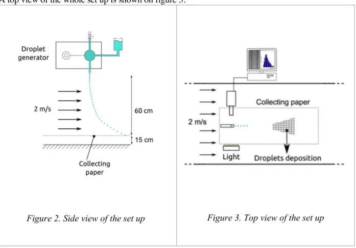
The used droplet generator, which is designed in Gembloux Agro-Bio Tech, ensure two regimes of liquid break up: free and forced break up regimes. The droplet generator is equipped by a liquid chamber, a hole of the water supply, a hole to remove air from the chamber and an injector tip to eject the liquid. One side of the liquid chamber is a piezoelectric element, which is periodically deformed by a sinusoidal signal what generates regular acoustic waves in the liquid jet. An illustration of the droplet generator is presented on the top part of the figure 2.
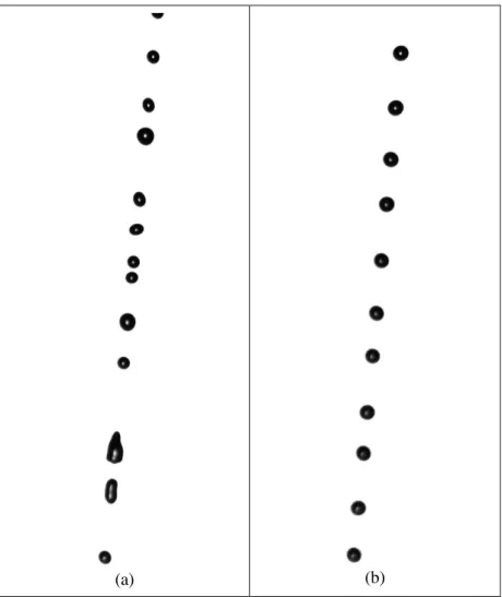
The free break up regime (figure 1) is described by the Rayleigh-Plateau breakup regime, which occurs when a cylindrical jet is discharged into gas with a low inertia in respect with its capillary forces. Theoretical developments showed that the growth of the most unstable perturbation breaks the jet in droplets of 1.89 times the jet diameter. Jet breakup can be controlled, e.g. using acoustic waves generated by piezoelectric element with the adequate wavenumber. The optimal breakup frequency, f [Hz], is defined as
f= 𝑣
9,016𝑟!
with v the jet average speed [m/s] and r0 the jet radius [m].
When the frequency of the signal is following the equation 1, a uniform stream of droplet is produced as illustrated on the figure 1 (b).
(a) (b)
Figure 1. Different droplet beak up regimes through the generator: (a) free break up regime, (b) forced break up regime
Spray mixture
Spray mixture was based on tinted distilled water using nigrosine powder at a volumetric concentration of 0.1 %, what may be useful to follow the spray deposits (the droplet deposit appears on the paper as dark spot on the paper).
Droplet size distribution of produced sprays
Spray generators characteristics were measured using a high speed shadow imagery technique. The imaging system uses a shadowgraphy setup, which involves a backlighted arrangement for image acquisition (De Cock and al., 2014) (Figure 3). A PIV camera (X-Stream™ XS-3, IDT) coupled with high magnification optics provides a field of view of 10x12 mm at a working distance of 130 mm. The spatial resolution is equal to 9.7 µm/pixel. With this magnification factor, droplets with a diameter ranging from 40 to 3500µm can be measured. The lighting is ensured by a LED array synchronized with the camera. Obtained images were analysed with a Particle Tracking Velocimetry Sizing (PTVS) algorithm developed in Matlab (De Cock and al., 2014).
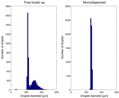
Figure 4 shows the droplet size distribution of tested sprays measured at 250 mm beneath the generator tip output. Droplets are ejected with a velocity of 3 m/s. As expected, the forced break up regime of the liquid results in more uniform droplets spectrum than the free regime. Some spray characteristics measured for the two regimes are presented in Table 1. The
uniformity of spray resulting of the forced break up regime is corroborated by a lower span value around 0.069. However, the span for the spray arising from the free breakup regime was 0.561, which is close to span value of CDA sprays.
Measurement configurations
Experiments were conducted in the wind tunnel facility of Gembloux Agro-Bio Tech (University of Liege). The closed circuit wind tunnel has overall dimensions of 25.0 m total length, 7.0 m working length, 2.0 m width and 2.0 m height for the working section. Wind in the tunnel was blown using a 1.2 m diameter bladed axial flow fan driven by a 22 kW motor. It allows to reach wind speeds from 0 to 6 m.s-1 adjustable via a speed controller Danfoss VLT6032. Tunnel air flow conditions were uniform with a maximum local variability of air velocity of 5% and a maximum degree of turbulence of 8% along the tunnel area. Tunnel wind speed was set at 2 m.s-1. Trials were performed under recommended conditions by ISO 22856 standard where temperature was 20 °C ± 1°C and relative humidity was 80% ± 5%. The single droplet generator was used inside the wind tunnel at 60 cm from the virtual wind tunnel floor, which corresponds to 15 cm from the real wind tunnel floor. The droplets were collected on a white paper placed on the virtual wind tunnel floor, which has overall dimensions of 4.0 m length and 1.0 m width.
A top view of the whole set up is shown on figure 3.
Figure 3. Top view of the set up Figure 2. Side view of the set up
Figure 4. Droplet size distribution in numbers: left side: free break up regime, right side: forced break up regime (frequency: 6000 Hz)
Table 1. Spray characteristics of tested sprays
DV10 (µm) DV50 (µm) DV90 (µm) Span Free break up regime 219 303 390 0.561 Forced break up regime 259 267 277 0.069
Results and discussion
Figure 6. Measured droplet diameters at different distances from the generator
Figure 7. Example of merged drops in the case of a forced break up regime at 160 mm from the injector tip.
The spray deposits on the ground from the free break up liquid regime under 2m/s downwind velocity are presented on figure 5. The first droplets spots were observed 15 cm from the generator and droplets traveled until 1m, however, the image is cut at 60 cm because further spray spots are not noticeable. Spray deposits are marked by a beam of droplets with a steady width in the beginning and it slightly increase when the traveled distance rise. The observed distribution of droplet spots was bimodal, which is related to droplet size.
On this basis, diameters of droplets expected to deposit on the ground at different distances from the generator were measured (figure 6). The results were corroborated with the figure 5 as droplets deposit according to their diameter: big droplets were found near the generator and smaller droplets travel far away (35 cm).
Unexpected results from the mono-disperse spray were observed since the same deposits pattern on the ground was obtained. This result is due to emerged droplets throughout (far away from the ejection source) what may affect droplet sizes and, hence, the spray uniformity (figure 7).
Much effort to maintain the uniformity of droplets diameters within the spray is required through other techniques such droplet on demand.
Conclusion
The free break up regime of the liquid results in a bimodal pattern on the ground, which is related to droplet sizes under a 2 m/s downwind. In this study, several problems within the forced break up regime can’t lead to make comparisons between the two techniques since similar results in terms droplets spots were observed. Much focus on the forced break up regime is needed to relate droplet size to spray drift.
References
De Cock, N., Massinon, M., & Lebeau, F. 2014. Agricultural spray measurement by high-speed shadow imagery. Proceedings of International Advances in Pesticide Application. Massinon, M., Dumont, B., De Cock, N., Ouled Taleb Salah, S. and Lebeau, F. 2015. Study of retention variability on an early growth stage herbaceous plant using a 3D virtual spraying model, Crop Protection 78: 63-71.
Nuyttens, D., De Schampheleire, M., Verboven, P., & Sonck, B. 2010. Comparison between indirect and direct spray drift assessment methods. Biosystems Engineering, 105(1): 2-12.
Ozkan, H. E., Miralles, A., Sinfort, C., Zhu, H. & Fox, R. D. 1997. Shields to Reduce Spray Drift. Journal of Agricultural Engineering Research 67: 311-322.
Qi, L., Miller, P.C.H., & Fu, Z. 2008. The classification of the drift risk of sprays produced by spinning discs based on wind tunnel measurements. Biosystems Engineering 100(1): 38-43.