Science Arts & Métiers (SAM)
is an open access repository that collects the work of Arts et Métiers Institute of
Technology researchers and makes it freely available over the web where possible.
This is an author-deposited version published in: https://sam.ensam.eu Handle ID: .http://hdl.handle.net/10985/8822
To cite this version :
Fatiha MEKRI, JeanFrederic CHARPENTIER, Seifeddine BENELGHALI, Xavier KESTELYN -High Order Sliding mode optimal current control of Five Phase Permanent magnet Motor under Open Circuited phase Fault Conditions - In: 2010 IEEE Vehicle Power and Propulsion Conference (VPPC), France, 2010-09 - 2010 IEEE Vehicle Power and Propulsion Conference (VPPC) - 2010
Any correspondence concerning this service should be sent to the repository Administrator : [email protected]
High Order Sliding mode optimal current control of
Five Phase Permanent magnet Motor under Open
Circuited phase Fault Conditions
Fatiha Mekri*, Jean-Frederic Charpentier*, Seif Benelghali*, Xavier Kestelyn**.
*IRENav: Institut de Recherche de l’Ecole Navale EA3634 - BP 600, 29240 BREST ARMEES, France ** L2EP, ENSAM. 8, boulevard Louis XIV 59046 Lille cedex
E-mail : [email protected], [email protected]
Abstract— Electrical marine propulsion systems are characterized by very high level requirements in terms of compactness, acoustic behavior and reliability. In this particular context, the use of multiphase PM machines associated with VSI drives appears to be a very efficient solution. Presented work focus on the use of such a system in open circuited phase fault conditions. With this kind of system it is possible to determine optimal current references which maximize the torque density of the system when one or two phases are open circuited. Classical linear controllers (as PID for example) cannot provide a correct tracking of these optimal current references because they have a highly dynamical behavior. We propose in this paper to combine this optimal current reference generation with High Order Sliding Mode (HOSM) control. This kind of solution allows a good tracking of these unconventional current references with a fixed switching frequency for the VSI. This method is validated experimentally using a low power experimental set-up which associates a phase PM machine with a DSP controlled IGBT 5-leg VSI drive.
Keywords-Marine Propulsion, multi phase machine, fault tolerant, nonlinear control, Sliding Mode.
I. INTRODUCTION
AC Multi-phase motors are widely used in marine propulsion. In this application, the number of phases, greater than three, is not only justified by the induced power partition between the different phases but also by a smoother torque and especially a higher fault tolerance. Thanks to the advance in Digital Signal Processors (DSP) and high power switches such as Insulated Gate Bipolar Transistors (IGBT) these multi-phase motors can now be controlled by Pulse Width Modulation (PWM) Voltage Source Inverter (VSI) even for high power marine propulsion [1,2] (>1MW). This kind of supply increases the flexibility of control and allows using unconventional strategy of control. Used with Permanent Magnet synchronous motors, this solution also improves the compactness of the propulsion system and improves the reliability of the system using fault tolerant strategies [3, 4]. Multi-phase PM machines are thus attractive since a higher torque density and fault tolerance can be expected with a simpler design and with low torque pulsations [5]. This
particular specification corresponds to civil and military ship propulsion current context.
One of the most common ways to use multiphase for fault tolerant marine propulsion machine is to use a double or triple star machine. However this solution leads usually to disconnect an entire star and to run the system in a significantly reduced power in fault mode. One of the major specifications particularly in military electric propulsion ship is to maintain in a fault mode a smooth torque with a high level of torque. With this kind of specifications the use of a multiphase machine with N identical and regularly shifted windings can be very advantageous because it allows maintaining a high level of torque disconnecting only the faulted phases. This is why this paper focuses on the optimal control of multiphase machine in fault tolerant open circuited phase mode.
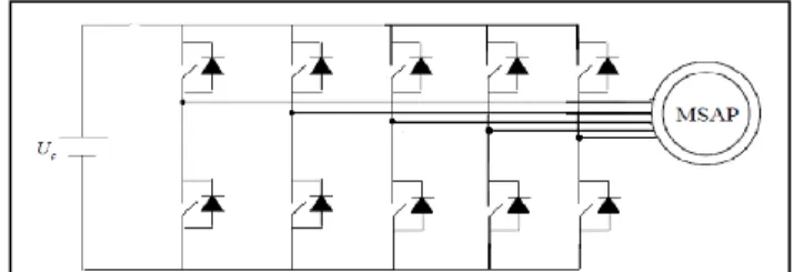
A method is presented to determine optimal references for the machine currents for open circuited phase mode. These references are calculated to minimize the copper losses for a given constant torque. So this strategy leads to maximize the torque density in open circuited phase mode. This solution is characterized by strongly non sinusoidal current references with high dynamics. So we propose to associate this optimal current reference generation with High Order Sliding Mode (HOSM) control which appears to be particularly suited to this case. This global strategy has been implemented in a low power lab scale PM 5 phase machine supplied by a DSP controlled VSI (Figure 1). Experimental results show the good behavior of the system for one or two open circuited phase operations
II. MODELING MULTIPHASE MACHINE
The electric equation of a 5 phase PM synchronous machine in the natural base is given by the following expression for each phase (here the kth phase).
s k k s k k d v R i e dt
(1)Where Rs is the resistance of a stator phase, sk is the stator flux vector created in the kth phase by stator currents and
k
e
is the EMF induced in this phase by the permanent magnet rotor flux.We consider that the k phases are regularly shifted, and that there is no saturation and no saliency effects. Then we can obtain a relation between the current vector (5 components) and stator flux vector [6, 7, 8, 9].
s
( )
i
(2)
1 2 2 1 1 1 2 2 2 1 1 2 2 2 1 1 1 2 2 1( ,
)
n n s
L M
M
M
M
M
L
M
M
M
M
M
L
M
M
L
mat
B
M
M M
L
M
M
M M
M
L
Where L is the inductance of a phase, M1 the mutual inductance between two adjacent phases (electrical shift angle
2 5
and M2 is the mutual inductance between two phases shifted of an electrical angle of 4
5
)
The electromagnetic torque developed by the machine is equal to:
em
.
e i
T
(3)On the other hand, the mechanical equation of the machine is:
em
d
T
J
f
dt
This set of equations allows to characterize the electromechanical behaviour of a 5 phase PM machine.
III. CURRENT REFERENCE EXTRACTION
A. Direct method to determine currents reference.
In normal operations, minimizing joules losses for a constant given torque Tmax leads to express the optimal current references of each phase [10, 11] as:
ref
e
i
A
(4) With:A
T
max2e
Then obtained theoretical optimal torque is:
2 max
(
)
e
e
e
e
T
i
A
A
(5)If in a 5 phase PM machine, this strategy is applied considering in (4) only the 1st and third harmonics of the EMF, it is possible to use a 5 phase transform with two rotating frames. This transformation is a generalization of the Park transform for multiphase system [12, 13, 14]. If a wye connection is done, the current is nullified in the zero sequence. In this case the current references are constant in steady state and in normal mode in the two d-q rotating frames [9]. So it is possible in normal operation to use classical controller as for example PID controller which allows a good control of such current references If we consider that an open circuit fault has occurred in one phase, torque ripples appear with this classical control of the motor. These ripples are linked to the interaction between the non-symmetrical system of currents and symmetric system of electromotive forces. To avoid these torque ripples, an adaptive method to determine current references is described in the next part of this paper.
B. Adaptive method to determine currents reference
Let us consider the case where one phase of PM five phase machine is not fed ( ith phase for example), and where the machine has sinusoidal EMF. If a classical control as described in previous paragraph is used, the expression of the torque in fault mode is given by the following equation:
0 (
2
)
em(
1) cos 2
2(
1)
emT
T
t
q
t
i
q
q
(6)Where Tem0 is the torque developed by the machine in normal operation and q is the number of phases.
Therefore, it can be noticed that this solution leads to high values of torque ripples (second term of the equation).
To ensure continuity of operation of the machine, and to minimize torque ripple with minimum copper losses when an open phase fault appear, a new adaptive control strategy have been proposed in [10].
With this method the faulty phases are firstly detected. Then a new system is considered. The new system comprises only the phases that are not in fault. Therefore, the torque is in this case the scalar product of the current vector and EMF vector of the new system divided by the machine rotational speed. For example in the case of one or two phases fault the new EMF vector for each non-faulted phase (here the first phase) is given by the following expression:
1 1 1
1
'
'
q k k ke
e
h e
q
(7) Where q’ is the number of active phases and hk=1 for active phase and hk =0 for faulted phases.Thus a new expression of equation (4) can be established as follows:
'
max2'
T
A
e
'
'
'
refe
i
A
(8)This strategy remains valid in normal and fault operation for obtaining a constant and filtered torque at minimum copper losses. The general structure of the control scheme is given in fig. 2.
Classically PM machine has trapezoidal EMF. Fig. 3 presents the waveform of the EMF of such 5 phase PM machine. This EMF waveform corresponds to experimental measurements in a 5-phase PM machine of low power which is located in our lab. Table 1 presents the harmonic contents of this EMF waveform.
Fig. 4(a, b) and 5(a, b) present the obtained optimal current references obtained with equation (8) when one or two phases are in fault in the natural frame (fig. 4(a) and fig. 5(a)) and in the two rotational d-q frames associated with the transformation presented in paragraph II (generalized park transform) (fig. 4(b) and fig 5(b)). We can notice that these currents have a high dynamic behavior in the natural frame and even in the rotating d-q frames.
Fig. 2. Global strategy to determine currents reference of the multiphase machine
Fig. 3. EMF of the experimental 5 phase PM-machine
TABLE 1
HARMONIC CONTENTS OF THE BACK EMF THE EXPERIMENTAL 5 PHASE
PM-MACHINE.
Fig. 4(a). Optimal current references (in p.u.) in the natural frame for single open circuited phase.
Fig. 4(b). Optimal current references (in p.u.) in the two dq frame for one open circuited phase
Fig. 5(a). Optimal current references (in p.u) in the natural frame for two open circuited phases
Fig. 5(b). Optimal current references (in p.u.) in the two dq frame for two open circuited phases
Harmonic number 1 3 5 7 Relative RMS Amplitude 100 23 7.31 0.82 0 0.005 0.01 0.015 0.02 0.025 0.03 0.035 0.04 -15 -10 -5 0 5 10 15 EMF(V) Time (s) pθ Estimated EMF Deletion of zero sequence EMF Current identification Current regulator Detection of fault Ti Tref Iref EFM/ Ω Imes +
-
0.8 0.85 0.9 -2 0 2 0.8 0.85 0.9 -40 -30 -20 -10 0 10 20Idqp_ref (pu) Idqs_ref (pu)
Time (s) Time (s) 0.8 0.82 0.84 0.86 0.88 0.9 0.92 -15 -10 -5 0 5 10 15 Iref (p.u) Time (s) 0.8 0.82 0.84 0.86 0.88 0.9 0.92 -2 -1 0 1 2 Iref (p.u) Time (s) Time (s) Time (s) 0.8 0.85 0.9 -2 -1 0 1 0.8 0.85 0.9 -4 -2 0 2 4
Idqp_ref (pu) Idqs_ref (pu)
Time (s) Time (s)
So when the speed increases in fault case, classical linear controllers (as PID for example) cannot provide a correct tracking of these current references in the natural or in rotating dq frames. It is necessary to use non linear current control strategies to insure a good tracking of the references. The most common non linear control strategy is the hysteresis control mode which has been implemented with success in [10]. However with this very simple control mode the switching frequency is not controlled and depends of the hysteresis bandwidth and the dynamic of the reference. In high power drives like naval propulsion drive, the increasing of switching frequency can leads to a too high level of switching losses and constraints in switches. We propose in this paper to use non linear control based on High Order Sliding Mode (HOSM). This kind of control is particularly suited to this application because it allows a good dynamic tracking of the references with a fixed switching frequency. This strategy can then be used in the two d-q frames used in normal mode operations or in the natural frame. In the first case this means that the same control scheme can be used directly in normal or in fault mode without changing the control configuration.
IV. HIGH ORDER SLIDING MODE CONTROL
The proposed control technique generalizes the basic sliding mode idea by acting on the higher order time derivatives of the sliding manifold, instead of influencing the first time derivative as it is the case in the standard first order sliding mode. This operational feature allows mitigating the chattering effect, keeping the main properties of the original approach [15].
To ensure currents convergence to their references, and to minimize the error between the current and its reference, a second-order sliding mode strategy is used. Let us define the following sliding surfaces for the first dq frames (A similar approach is done for the second dq frame).
1 _ 2 _ p dp dp ref p qp qp ref S I I S I I (13)
Where Idp, Iqp are the currents in the first dq frame Idq_ref, Ipq_ref are the transformation of the optimal references (eq 8) in the first dq frame.
It follows that 1 _ 1 1( , ) 1( , ) p dp dp ref p dp S I I S t x t x V (14) and 2 _ 2 2( , ) 2( , ) p qp qp ref p qp S I I S t x t x V (15)
Where 1(t,x), 2(t,x), 1(t,x), and 2(t,x) are uncertain bounded functions that satisfy:
1 1 1 1 1 1 2 2 2 2 2 2 0, , 0 0, , 0 m M m M
The main problem with HOSM algorithm implementations is the increased required information. Indeed, the implementation of an nth-order controller requires the knowledge of S , S, S,…, S(n–1). The exception is the super
twisting algorithm, which only needs information about the sliding surface S [16-17]. Therefore, the proposed control approach has been designed using this algorithm. The proposed second-order sliding mode controller contains two parts: 1 2 1 2 dp qp V u u V w w (16) Where 1 1 1 2 1 1 1 ( ) ( ) u sign S u S sign S and 1 2 2 2 2 2 2 ( ) ( ) w sign S w S sign S
In order to ensure the convergence of the sliding manifolds to zero in finite time, the gains can be chosen as follows [17].
2 2 4 ( ) ; 1, 2 ( ) 0 0.5 i i mi i Mi i i i mi i i mi i V. EXPERIMENTAL RESULTS
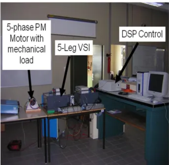
The presented method which combines line reference generation and HOSM controls have been implemented in a laboratory low power experimental set up. This installation comprises a 5-phase 6-pole PM machine with trapezoidal EMF (the EMF waveform is presented in fig.3) and a 5-leg DSP controlled VSI drive. Fig. 6 shows a snapshot of this experimental test-bed.
To validate the proposed method several tests has been done and compared with simulations results obtained using Matlab/Simulink.
Fig. 6. Snapshot of the experimental test-bed
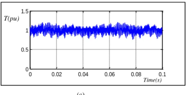
Figs 7 and 8 show simulation and experimental results under normal conditions with a HOSM simultaneous control of the two fictitious machines in the two d-q frame as presented in theory. We can see that simulation results, (fig.7), are quite similar to experimental ones (fig. 8). The only differences are related to the presence of torque ripple of high frequencies due to PWM modulation. These results show the efficiency of the proposed control strategy in normal operation. This strategy allows a good tracking of current references and a smooth torque.
Current references are generated using the method proposed in paragraph II-b in case of open circuit fault conditions. Experimental results are given in fig. 9 and fig. 10 for one open circuited phase at full speed.
(a)
(a)
(b)
(c)
Fig.7. Matlab simulink simulation in normal operation: (a, b) Current in five phases of machine, (c) torque.
Thanks to a good efficiency of the proposed method, we can see that the torque remains almost constant in this case.
Fig. 10 (a) presents experimental current with its reference and Fig. 10 (b) the torque for this fault case. These results show that the chosen strategy leads to a good tracking of the optimal current references in open circuited phase condition. That means that the studied methodology insures good performances of the current control.
(a) (b) 0.8 0.85 0.9 0.95 -1.5 -1 -0.5 0 0.5 1 1.5 I1 ,2 , 3 (p.u) Time(s) 0.8 0.85 0.9 0.95 -1.5 -1 -0.5 0 0.5 1 1.5 I4,5(p.u) Time(s) 0 0.02 0.04 0.06 0.08 0.1 -1.5 -1 -0.5 0 0.5 1 1.5 I1 ,2 , 3 (p.u) Time(s) 0 0.02 0.04 0.06 0.08 0.1 -1.5 -1 -0.5 0 0.5 1 1.5 I4 ,5 (p.u) Time(s) 0.8 0.85 0.9 0.95 0 0.5 1 1.5 Time(s) T(pu)
(c)
Fig.8. Experimental results in normal operation: (a, b) Current in five phases of machine, (c) torque.
Fig. 9. Experimental results: Optimal currents of machine for single open circuited phase.
(a)
(b)
Fig.10. Experimental results: (a) current phase with its optimal reference (b) Torque.
VI. CONCLUSION
In the context of electrical marine propulsion, the torque density and the fault tolerance of the electrical propulsion motors are key features. Multiphase PM machines associated with DSP controlled VSI appears to be one of the more convenient solution to reach this goals. This paper focuses on the treatment of open circuited phase default in such systems. A method based on adaptive on line optimal generation of
optimal current references associated with High Order Sliding Mode control is presented. This method allows to minimize the copper losses for a given constant torque then to maximize the torque density in default cases. Experimental results show the efficiency of the proposed method even in severe fault cases.
REFERENCES
[1] E. Levi, E. Bojoi, F. Profumo, H. Toliyat, and S. Williamson, “Multi-phase induction motor drives - a technology status review." IET ElectricPower Applications, vol. 1, no. 4, pp. 489-516, 2007.
[2] NORTON P., THOMPSON P,‘The naval electric ship of today and tomorrow’. Proc. 3rd All Electric Ship Symp, Paris,France, 26–27 October 2000, pp. 80–86
[3] P. Letellier, High power permanent magnet machines for electric propulsion drives," in Proc. of the All Electric Ship Symposium, Paris, France, 26-27 october 2000, pp. 126-132.
[4] L. Parsa, H. A. Toliyat ”Multi-phase Permanent Magnet Motor Drives” in Proceedings of the IEEE-IAS annual meetings 2003, Salt Lake City (Utah), October 12-16,
[5] F. Scuiller, E. Semail, J.-F. Charpentier, P. Letellier, ”Multi-criteria-based design approach of multi-phase permanent magnet low-speed synchronous machines, IET Electr. Power Appl., 2009, Vol. 3, Iss. 2, pp. 102–110
[6] Leila Parsa, Hamid A.Toliyat ‘’Five- Phase Permanent –Magnet Motor Drives’’ IEEE Transactions on Industry applications, Vol.41.NO.1, January/ February 2005 pp 30-37.
[7] F. Locment, E.Semail, Kestelyn ‘’ Vectorial Approach Based Control of a seven- phase Axial Flux Machine Designed for Fault Operation, IEEE Trans on Ind. Electronics, Vol 55 Issue 10,Oct 2008-pp 3682 - 3691
[8] Jean Philippe Martin, Serge Pierfederici, Farid Meibody Tabar, Paul Letellier, synthèse des méthodes de filtrage du couple des MSAP Polyphasées en modes normal et dégrade’’ European Journal of Electrical Engineering- 2007, Volume 10, n°1-2 pp 117-149.
[9] X.Kestelyn,’’ Modélisation vectorielle multimachines pour la commandedes ensembles convertisseurs machines polyphasés’’, Ph.D. thesis of, Universty of Sciences and Technologies of Lille, 2003 [10] X.Kestelyn, ‘’Generation of on line optimal current references for
multi-phase permanent magnet machines with open circuit multi-phases’’ in proceedings IEMDC 2009, Miami may 3-6 2009 pp 689-694, [11] Suman Dwari, Leila Parsa ‘’An Optimal Control Technique for
Multiphase PM Machines Under Open – Circuit Fautls’‘,IEEE Transactions on Industry Electonics, Vol.55.NO.5, May 2008 pp 1988 - 1995.
[12] Emil Levi, Martin Jones, Slobodan N.Vukosavic, Hamid.A .Toliyat ’’ Operating Principles of a Novel Multiphase Multimotor Vector – controlled Drive. IEEE Transactions on Energy Conversion, Vol.19.NO.3, September 2004 pp 508-517.
[13] Leila Parsa, Hamid A.Toliyat ,’’ Sensorless Direct Torque Control of Five Phase Interior Permanent Magnet Motor Drives’’, IEEE Transactions on Industry applications, Vol.43.NO.4, July/August 2007 pp 952 - 959.
[14] E. Semail, A Xavier Kestelyn, Alain Bousscayrol, ‘’ Sensitivity of a 5 phase Brushless DC machine to 7th harmonic of back-electromotrice force’’, PESC 2004 IEEE Power Electronics, Germany, June 2004, CD- ROM.
[15] L.Fridman and A. Levant, Sliding Mode Control in Engineering, Marcel Dekker, Inc., 2002, Chap. 3 Higher Order Sliding Modes, pp. 53-101 [16] F. Valenciaga et al., “High-order sliding control for a wind energy
conversion system based on a permanent magnet synchronous generator,” IEEE Trans. Energy Conversion, vol. 23, n°3, pp. 860-867, September 2008.
[17] A. Levant et al., “Integral high-order sliding modes,” IEEE Trans. Automatic Control, vol. 52, n°7, pp. 1278-1282, July 2007.
0 0.02 0.04 0.06 0.08 0.1 0 0.5 1 1.5 Time(s) T(pu) 0 0.01 0.02 0.03 0.04 -2 -1 0 1 2 I(p.u) Time(s) 0.01 0.015 0.02 0.025 0.03 -2 -1 0 1 2 I(p.u) Time(s) 0 0.01 0.02 0.03 0.04 0 0.5 1 1.5 Time(s) T(pu)