Science Arts & Métiers (SAM)
is an open access repository that collects the work of Arts et Métiers Institute of Technology researchers and makes it freely available over the web where possible.
This is an author-deposited version published in: https://sam.ensam.eu
Handle ID: .http://hdl.handle.net/10985/7471
To cite this version :
Christophe CLAUDIN, Joël RECH, Alexandre MONDELIN, Guillaume FROMENTIN - Effects of a straight oil on friction at the tool-workmaterial interface in machining - International Journal of Machine Tools & Manufacture - Vol. 50, n°8, p.681-688 - 2010
Effects of a straight oil on friction at the tool-workmaterial interface in machining C.Claudina, A.Mondelina, J. Recha*, G.Fromentinb
a Université de Lyon, Ecole Nationale d’Ingénieurs de Saint Etienne, Laboratoire de Tribologie et Dynamique des Systèmes, CNRS UMR 5513, 58 rue Jean Parot, 42023 Saint-Etienne, France b Arts et Métiers ParisTech, LaBoMaP, 71250 Cluny, France
* Corresponding author. Tel.: +33 677098123; fax: +33 477437539
E-mail address: joel.rech@enise.fr
Abstract
The quantification of friction coefficient along the tool-workmaterial interface in machining remains an issue in tribology. This paper aims identifying the evolution of friction coefficient for a large range of sliding velocity during the machining of a AISI4140 steel (290 HB) with a TiN coated carbide tool. The influence of a straight oil is investigated compared to a dry sliding situation (dry machining). It has been shown that, in dry machining, friction coefficient decreases with the sliding velocity until reaching a downer limit around 0.2. On the contrary, the presence of a straight oil decreases significantly friction coefficients to a value around 0.1. Additionally, the friction coefficient becomes independent from the sliding velocity. It also been shown that a straight oil is able to penetrate the pin-workmaterial interface even if a very high contact pressure is present (~3 GPa). The penetration duration is very fast, whereas its evacuation duration is much higher and strongly dependant on sliding speeds.
1. Introduction
Many efforts are being undertaken to develop advanced machining processes using no coolant in order to eliminate problems associated with the cutting fluid management: waste generation, machining cost, parts cleaning, recycling of chips, health hazard, etc… However, the large majority of cutting operations till uses cutting fluid since manufacturing procedure and machines cannot be modified easily without a detailed technical and economical analysis. It is usually admitted that the basic functions of a cutting fluid are to provide cooling and lubrication and thus reducing the severity of the contact phenomena at the cutting tool-chip-machined surface interfaces [1]. However, the selection of the type of cutting fluid for a particular machining operation is often hazardous. The basic methodology consists in trying the new fluid in the machine and to observe the consequences. Another way of testing consists in using laboratory cutting tests in order to compare some macroscopic measurements such as forces and torque. One the most popular tests is the tapping torque test (ASTM D-5619), or the drilling test (ASTM A830-85) [2]. These methods may compare several fluids for a couple of materials (cutting tool substrate / workmaterial) but can neither provide the modification of the friction coefficient, nor explain the tribological mechanisms at the interface. It is basically a statement: better or worse. The conclusion is valid for the investigated cutting operation but it is not possible to extend them to other cutting conditions or to another cutting process (example: milling). So other authors have proposed to transpose this method to other cutting processes. For example, Cakir [3] and Jayal [4] use forces measurement to compare cutting fluids in turning whereas [5] investigated the influence of cutting fluids on mechanical actions in milling.
A huge number of authors prefer making cutting wear tests to evaluate the performance of cutting fluids (example: [5,6]). Such tests are expensive, time consuming and very sensitive to little variation of any parameter.
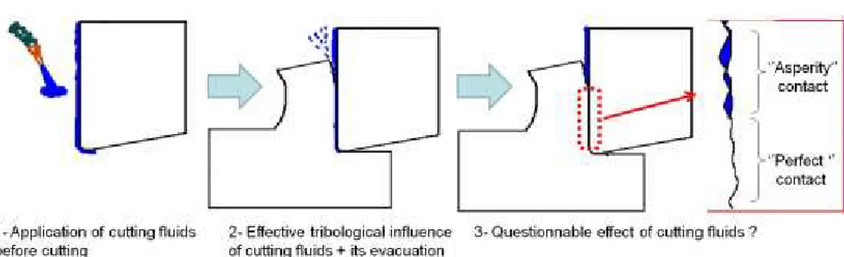
As a summary, the following actions of cutting fluids are reported in the literature. First a cooling action of the chip back surface, resulting in curl increase, may reduce the tool-chip contact length (Fig.1). Secondly, the pressure of cutting fluid may promote the plastic deformation in the primary shear zone (see Fig.1). Finally, at the tool-workmaterial interface, the action of cutting fluids has been intensively discussed in the scientific literature. Many contradictory mechanisms are proposed. Some support the idea of physical action (adsorption, capillarity, etc.) [7,8] or chemical action (chemisorption, evaporation, chemical reaction, etc.) [8,9,10]. This idea is rejected by [11]. He argues that no fluid can remain in this interface due to the very high contact pressure in the secondary shear zone (up to 3 GPa). Other authors, such as [12], propose an intermediate explanation. They assume that workmaterial fills out even the microscopic valleys and hills at the beginning of the tool-chip contact area (Fig.2), which does not enable the cutting fluid to remain. At the rear of the contact, far from the cutting edge, the decrease of contact pressure should enable the penetration of cutting fluids through capillarities. Finally a lot of authors [1,8,12,13] support the idea that a cutting fluid can remain some little time at the tool-chip interface as shown in Fig. 2. After some seconds, it is usually admitted that no fluid can remain at the interface in a zone where contact pressures are too high. However no quantified critical values of contact pressure and of persistence duration are available.
However, all these investigations do not provide quantitative date about the influence of cutting fluids on friction and on heat partition at the tool-workmaterial interface. This matter of fact leads specialists in modeling (numerical and analytical) of cutting processes to avoid the application of cutting fluids. It is only possible to mention some analytical models who have tried to introduce the influence of cutting fluids [14] even if the choice of the friction coefficient has not been justified.
Based on this statement, a lot of laboratories have tried to use a more fundamental approach through elementary tribological tests. The problem is that the tribological conditions supported by cutting fluid at the tool-workmaterial interface (contact pressure up to 3 GPa, temperature up to 800°C since Trent [1]) are not simulated by current laboratory tests. Different tests are applied to evaluate metalworking fluids: the Pin and Vee method (ASTM D2625-94), the four balls wear test (ASTM D-4172), pin on disc test, etc… However, it is impossible to accept these values and to transfer it into cutting models. Indeed, the major problem is that, in such tests, the continuous sliding contact occurs by cyclic reintroduction of the same surface element from the counter-material. This situation is called a closed tribosystem. On the contrary, in cutting (Fig. 1), after the strong plastic deformation occurring in the primary shear zone, a freshly formed surface made of workmaterial slides against the tool in the secondary shear zone. This configuration is called an opened tribosystem. Thus various researchers have developed specially designed tribometers in order to enable pins to rub a fresh surface [15,16,17,18]. Among them [16,17] use a bar made of the workmaterial. The bar has been regenerated some minutes before making the friction tests, which enables some contamination of the surface (example: oxidation). The question is: does this contamination influence friction results? On the contrary, [18] uses a tube continuously
regenerated by a cutting tool located some millimeters before the pin. It is the single author to have developed an opened tribometer located in an inert gas. Between the regeneration of the surface and the friction, there is only some tenths of seconds. Hence any contamination is possible and the pin rubs on a fresh surface. [15] has reproduced a similar tribometer as [18]. It has been assumed that no oxidation occurs on the surface. Finally, it has been shown by [19], that, under extreme contact pressure, no difference exists between the two tribometers developed by [15] and [16] during the dry sliding of a AISI4142, neither in terms of friction coefficient, nor in terms of heat partition coefficient. Hence it has been assumed that, even if an oxidation may exist between the regeneration of the surface and the friction during the application of the tribometer developed by [16], it does not significantly influenced results under such severe contact conditions. So it is believed that the principle of the tribometer developed by [16] is efficient to simulate similar tribological conditions as the one occurring at the tool-workmaterial interface.
However these tribometers have never been applied to investigate the influence of cutting fluids. Hence there is a need to adapt such tribometers in order to quantify the influence of a cutting fluid. As a consequence the objective of this paper is to present the design of this new dynamometer based on the principle proposed by [16] and to quantify the influence of a cutting fluid for a large range of sliding velocity and for a high level of contact pressure in order to quantify the evolution of friction coefficient and of heat partition coefficient along the tool-workmaterial interface. The paper focuses on the characterization of TiN coated carbide pin rubbing a AISI4140 steel (290HB). Two configurations of lubrication have been considered:
lubrication with a pure straight oil containing any additives
2. Experimental set-up
The principle of the tribometer has already been applied and validated for several previous works [16,20] published in various scientific journal including the present journal (Fig. 3). The workmaterial is simulated through a cylindrical bar made of steel AISI 4140 (290 HB). Cutting tools are simulated through pins made of cemented carbide with a similar grade to the one used for cutting tools dedicated for AISI4140 steel machining (90% WC – 10% Co – average grain size ∼ 0.8μm).
In order to eliminate the potential influence of surface roughness, pins have been polished to reach a low surface roughness (Ra < 0.3 μm) which is coherent with a
typical surface roughness on a finely ground carbide cutting tool. Pins have been coated with TiN coating deposited by (PVD – cathodic arc – ∼2μm – monolayer).
Concerning bars, after each friction test, a cutting tool refreshes the surface ploughed by the pin. A belt finishing operation is also performed in order to obtain a very low surface roughness (Ra ∼ 0.1μm) and a constant surface for each test.
Each friction test has 20 seconds duration approximately.
Compared to the tribometer developed by [16,20], the new tribometer is based on a CNC lathe instead of manual lathe (Fig. 3). The pneumatic jack is replaced by a hydraulic jack. The mechanical structure and the instrumentation of the tribometer have also been modified. The new version has much higher stiffness in order to measure friction coefficient under extreme contact pressure and very low sliding velocities.
Finally, the new version enables to apply a cutting fluid under defined conditions (pressure, orientation, flow rate, temperature, etc.).
The pin is maintained by an instrumented pin-holder which is able to provide data about the instantaneous heat flow (Ø) entering into the pin. Readers interested in having details about this heat flow measuring system should read the work of [15]. The pin-holder is fixed onto a dynamometer in order to provide the normal force Fn and
tangential force Ft (macroscopic forces). The apparent friction coefficient is provided by the ratio between the tangential and the normal forces, taken as an average value of the stable zone. t app n F µ F (1)
Where Ft : tangential force – Fn : normal force
The term ‘apparent friction coefficient’ is used since it differs significantly from the ‘local friction coefficient’ induced by adhesion at the pin-workmaterial interface (Fig. 3). In deed the macroscopic forces measured by the tribometer include the friction phenomena (adhesion) and the plastic deformation of the workmaterial, which cannot be neglected under such severe contact conditions (Fn ~ 1000 N). As stated by [20], a pin having a diameter 9 mm lead to an average contact pressure around 3.5 GPa for a AISI4142 steel which is a similar microstructural state than the AISI4140 steel. The order of magnitude of contact pressure is coherent with typical values obtained during machining of steels (Fig. 1).
The apparent friction coefficient previously introduced (1) could be decomposed into two components [21]:
t
app app def
n
F
µ µ µ
F
where µapp is the apparent friction coefficient, µadh is the adhesive part and µdef is the deformation part.
To extract the part of adhesion and deformation from the apparent friction coefficient, it is possible to use an analytical model developed by [21]. This model is independent of contact material properties and is based on the following hypothesis:
- The pin is considered to be infinitely rigid
- The workmaterial has a perfectly plastic behavior (no spring back) - The contact surface is the frontal part of the hemispherical pin
For each point of the contact surface, an elementary mechanical action is considered, which can be decomposed into two parts:
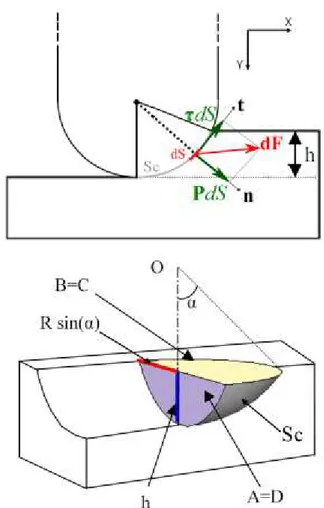
dS P dS P n (3) dS dS τ t (4) P dS dS dF n t (5) Sc
F dF (6)Where n and t are respectively the normal and the tangential unit vector of the considered elementary surface. dS is an elementary area of the contact surface , P is the normal contact pressure, is the tangential reaction force per unit area, F is the resulting force of the global mechanical action of the pin on the sliding surface and Sc is the
contact surface.
The interfacial friction coefficient (adhesive friction coefficient) µadh is defined by:
adh P
(7)
Thus, macroscopic normal and tangential forces (which are measured during friction tests, Fig. 4) are the sum of elementary mechanical actions:
= ( ) = ( ) Sc P dS dS
Fn F Y Y n Y t Y Y (8) = ( ) = ( ) Sc P dS dS
Ft F X X n X t X X (9)( ) A P C
Ft X (11)
with ( ) = ( )
Sc Sc
A D
dS n X
dS t Y : the projection of the contact surface Sc along X .( ) = ( )
Sc Sc
B C
dS n Y
dS t X : the projection of the contact surface Sc along Y .Areas of these projection surfaces (illustrated Fig. 4) can be calculated by:
2 1 [2 - sin(2 )] 2 A D R (12)
2 sin( ) 2 B C R (13)Where is the angle between the pin axis and the contact surface periphery (Fig.4) and R is the radius of the pin hemispherical end.
Therefore the apparent friction coefficient can be obtained as a function of the adhesive friction coefficient: - - adh app adh A C µ A P C µ B P D B D µ (14)
Finally, the adhesive friction coefficient is estimated from experimental measurements by: - app adh app B µ A µ C D µ (15) 3. Design of experiments
In this work, twovariables have been investigated:
- A range of sliding velocities: from 10 to 300 m/min, corresponding to the range of sliding velocities observable during the machining of a AISI4142 steel
For each test, the lubrication is applied on the workmaterial before the application of the pin. At the end of the rubbing test, the pin is moved away. Then the lubrication is switched off.
Each test configuration has been replicated at least three times.
4. Experimental results under continuous lubrication
The evolution of µapp versus sliding velocity is plotted in Fig. 5. It is remarkable to see the huge difference between dry sliding and lubricated sliding.
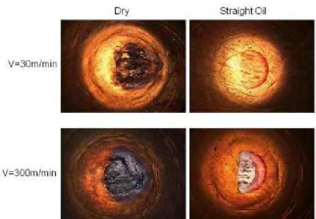
For dry sliding, µapp decreases very significantly from ~0.6 to 0.2. Adhesions are important on pins under low sliding velocities as observed in Fig. 6. This explains the large deviation of the experimental results in this range of sliding velocities. Since 60 m/min to 250 m/min, adhesions are more limited and the deviation of µapp decreases. Over 300 m/min, it is no use to conduct tests because of the rapid wear of pins observed after some seconds (Fig. 6): the coating is removed. These results are in accordance with previous results already published by [20].
On the contrary, sliding tests, conducted with straight oil, lead to very low values: µapp ~ 0.1. Moreover µapp is constant irrespective of the sliding velocity. Adhesions on pins are very limited as shown in Fig. 6. No wear is observable even for the largest value of sliding values (300 m/min). This shows that straight oil is able to penetrate the contact even if the contact pressure is very high (~2 – 2.5 GPa since [20]).
As mentioned in the previous section, the adhesive friction coefficient (µadh) can be extracted from µapp by applying the analytical model (eq.15) developed by [21]. Fig. 5
plots the evolution of the average adhesive friction coefficient versus sliding velocity. The general trend remains similar even if the values are something smaller.
During tests, the experimental set-up enables also to measure the heat flux transmitted to pins (Øpin). Fig. 7 plots the evolution of Øpin versus sliding velocity for the three
lubrication conditions.
Before making some analysis of Fig. 7, it is necessary to make some statements. Indeed, Øpin is only part of the total amount of energy (Øtot) dissipated during tests. During dry
friction tests, a large amount of heat remains in the workmaterial as shown by [20]. Additionally, in the case of lubricated tests, straight oil evacuates a significant part of this heat. So, it is possible to estimate the percentage of heat transmitted to pins ().
In a first step of analysis, it is possible to estimate the total energy Øtot by:
Øtot = Ftx V (2)
Ft : tangential force (N)
V : macroscopic sliding velocity (m/s)
By assuming that all the frictional energy is fully transformed into heat, can be estimated by: V Ft pin (3)
This means that % of the energy is transmitted to pins, whereas the workmaterial and the straight oil evacuate (1-)% of this energy. Theoretically, in dry sliding, depends on the effusivity of the two materials when sliding at a very low velocity (some mm/s). Unfortunately, for dynamic sliding interfaces, the standard thermal models are no more
valid as shown by [16]. Therefore, Fig. 7 reports experimental data, which are much closer to the reality.
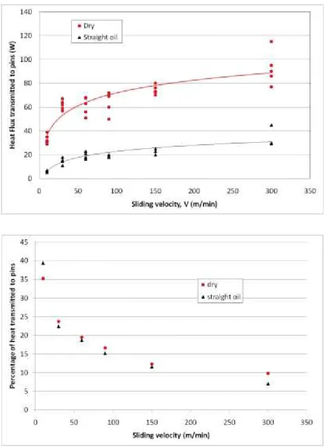
Based on these statements, it is possible to analyze the experimental results. First it appears that Øpin increases with sliding velocity. The curvature of the curve is not linear
due to the evolution of and µadh with sliding velocity, which contribute to limit the curvature. This result is in accordance with previous analysis made by [20] in the case of a AISI4142 steel.
Second, it appears that the deviation of the measurements is rather high. However this deviation is much smaller than the difference observed between the two configurations. Indeed, the application of a lubricant leads to a huge decrease of the heat transmitted to pins. The reason originates from two phenomena: the decrease of friction coefficient or the modification of heat partition (parameter ). As shown in Fig. 7, the evolution of the percentage of heat transmitted to pins exhibits almost no difference between dry and lubricated tests. This shows that straight oil does not modify the partition at the interface. So the difference of heat flux highlighted in Fig. 7 is only due to a modification of friction coefficient.
Additionally, it appears that the percentage of heat transmitted to pins varies with sliding speed. This enables to conclude that heat partition coefficient along the tool-workmaterial interface has to be dependent on the local sliding velocity as shown in Fig.1
These results contribute to clarify the question of the influence of oil in metal cutting. It confirms that the influence of oil is much more important for low sliding velocities, which has already been reported in the literature [1,8,12,13]. But, it is also shown that this lubrication effect remains very significant for large sliding velocities. As observed
in Fig. 5, the apparent friction coefficient µapp decreases from 0.2 to 0.1 in average under a 300 m/min sliding velocity. These new quantitative data will now enable scientists to consider the influence of lubrication in numerical modeling.
5. Experimental results under discontinuous lubrication
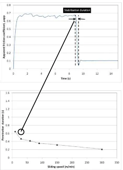
However, another question remains: how fast can a lubricant penetrate in a contact? How long can he stay and act in this contact? These questions are of primary importance in metal cutting especially when comparing a continuous or discontinuous cutting operation. Fig. 8 plots the evolution of friction coefficient when adding lubrication. It can be seen that the penetration duration is very low. Fig 8 plots the evolution of the penetration duration versus sliding speed. It reveals that the penetration duration varies between 0.6 to 0.2 s when increasing sliding speeds. This confirms that straight oil penetrates easily and rapidly into the contact.
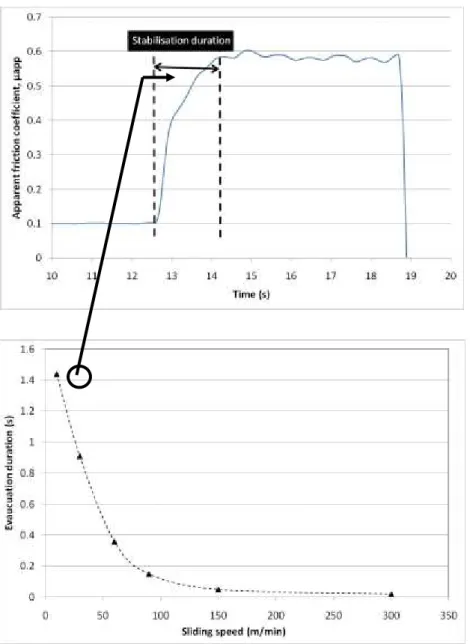
Fig. 9 shows the evolution of friction coefficient when stopping lubrication for the same sliding speed as in Fig. 8. It appears that friction coefficient increases rather rapidly but not suddenly. The influence of straight oil remains during more than a second. So it can be stated that oil has much more difficulty to be evacuated from the contact than to penetrate the contact. Fig. 9 plots the evacuation duration versus sliding speed. It reveals that, below 150 m/min, straight oil is able to remain in the contact. On the contrary, over 150 m/min, the evacuation duration is almost instantaneous.
This observation shows that, when considering a continuous cutting operation such as turning, oil is not able to remain in the contact since it is evacuated within some tenth of seconds. This duration is almost negligible compared to cutting durations (several
seconds). It is doubtful if straight oil can lubricate the contact as shown in introduction. However the cooling and flushing effects remain.
On the contrary, when considering interrupted cutting operations such as milling, it is possible to imagine that oil is able to remain in the contact during a large percentage of the cutting time. So the lubrication effect of straight oil can be clearly significant.
Hence this work provides new quantitative data about friction coefficients and heat partition coefficient at the tool-workmaterial interface with the presence of straight oil. It will now enable scientists to consider the influence of lubrication in numerical modeling, even if these data are only coherent with cutting phenomena occurring during some tenths of seconds, i.e. when cutting fluid remains at the tool-workmaterial interface.
5. Conclusions
This paper has investigated the influence of one straight oil on the friction coefficient at the tool-workmaterial interface during the machining of a AISI4140 steel with a TiN coated carbide tool. The investigation is based on a new tribometer dedicated to the characterization of friction coefficients under extreme conditions relevant to the ones supported in metal cutting.
The experimental set-up has shown that friction coefficient varies from 0.5 to 0.15 in dry sliding when increasing sliding velocity from 10 to 300 m/min.
It has also been shown that a straight oil leads to huge decrease of friction coefficient under low sliding velocities (V < 150 m/min) compared to dry sliding. Moreover it has
been revealed that friction coefficient under lubrication remains constant around 0.1 irrespective of sliding velocity.
Heat flux measurements have shown that the presence of oil does not modify the percentage of total heat transmitted to pins whereas it decreases very significantly the amount of heat transmitted to pins (absolute value) irrespective of sliding velocity. Additionally, it has been shown that the percentage of heat transmitted to pins varies with sliding velocity.
Finally, it has been shown that oil is able to penetrate instantaneously even if contact pressures are enormous (> 2 GPa). Then penetration duration decreases with sliding speed.
On the contrary, it has been observed that oil is able to remain approximately one second for low sliding velocity (< 100 m/min), whereas oil is immediately evacuated for faster values.
So this paper has contributed to quantify the influence of a straight oil on friction coefficient and on heat partition coefficient. This will enable to better take into account the effect of cutting fluid in modeling of a cutting operation.
References
[1] E.M. Trent, Metal Cutting, Butterworth Heinemann, 1991, ISBN 0-7506-1068-9. [2] Z. Pawlak, B.E. Klamecki, T. Rauckyte, G.P. Shpenkov, A. Kopkowski, The
tribochemical and micellar espects of cutting fluids, Tribology International 38 (2005) 1-4
[3] O. Cakir, M. Kiyak E. Altan, Comparison of gases applications to wet and dry cuttings in turning, Journal of Materials Processing Technology, 153-154 (2004) 35-41
[4] A.D. Jayal, A.K. Balaji, Effects of cutting fluid application on tool wear in machining: interaction with tool-coatings and tool surface features, Wear 267 (2009) 1723-1730
[5] J.M. Vieira, A.R. Machado, E.O.Ezugwu, Performance of cutting fluids during face milling of steels, Journal for Materials Processing and Technology, 116(2-3) (2001) 244-251.
[6] G. Lorenz, Reliable cutting fluid rating, CIRP Annals, 34(1) (1985) 96-99. [7] J.A. Williams, D. Tabor, The role lubricants in machining, Wear 43 (1977)
275-292
[8] J.A. Bailey, Friction in metal machining – mechanical aspects, Wear 31 (1975) 243-275
[9] H. Hong, A.T. Riga, J.M. Cahoon, Evaluation of overbasedsulfonates as extreme-pressure additives un metalworking fluids – Part I : Lthium and Potassium overbased sulfonates, Lubrication Engineering, 51(2) (1994) 147-150.
[10] R.W. Moulder, H.B. Silver, R.J. Syrett, Investigations of the activity of cutting oil additives I. Oil containing both organochlorine and organisulphur compounds, Wear 26(1) (1973) 27-37
[11] V.P. Astakhov, Elsevier, Tribology of Metal Cutting, 2006, ISBN 0-444-52881-4. [12] T.H.C. Childs, K. Maekawa, T. Obikawa, Y.Y amane, Metal machining : theory
and applications, Arnold, ISBN 0-340-69159-X
[13] M.E. Merchant, Cutting fluid action and the wear of cutting tools, Instn. Mech. Engrs 6(4) (1957) 163-167
[14] T. Cao, J.W. Sutherland, Investigation of thread tapping load characteristics through mechanistics modeling and experimentation, Int Jour of Machine Tools & Manufacture, 42 (2002) 1527-1538
[15] F. Zemzemi, W. Bensalem, J. Rech, A. Dogui, P. Kapsa, New tribometer designed for the characterization of the friction properties at athe tool/chip/workpiece interfaces in machining, Tribotest, 14 (2008) 11-25.
[16] C. Bonnet, F. Valiorgue, J. Rech, C. Claudin, H. Hamdi, J.M. Bergheau, P. Gilles, Identification of a friction model - Application to the context of dry cutting of an AISI 316L austenitic stainless steel with a TiN coated carbide tool,
International Journal of Machine Tools and Manufacture, 48 (2008) 1211-1223. [17] P. Hedenquist, M. Olsson, Sliding wear testing of coated cutting tool materials.
Tribology International 23(3) (1991) 143-150.
[18] M. Olsson, S. Soderberg, S.Jacobson, S. Hogmark , Simulation of cutting tool wear by a modified pin-on-disc test, Int. J. Mach. Tools Manufact, 29(3) (1989) 370-390.
[19] F.Zemzemi, Contribution à la comprehension des phénomènes tribologiques à l’interface outil-copeau-pièce lors de l’usinage de l’Inconel718, PhD Thesis, Ecole Centrale de Lyon, December 2007.
[20] F. Zemzemi, J. Rech, W. Ben Salem, A. Dogui, P. Kapsa, Identification of a friction model at tool/chip/workpiece interfaces in dry machining of AISI 4140 treated steels, Journal of Materials Processing Technology, 209 (2009) 3978-3990.
[21] J.M. Challen, P.L.B. Oxley, An explanation of the different regimes of friction and wear using asperity deformation models, Wear 53 (1979) 229–243.
Acknowledgements
Authors would like to express their gratitude to the TOTAL Company for the furniture of the lubricant.
Fig. 1. Evolution of the sliding velocity and of the contact pressure along the tool-workmaterial interface in the case of a AISI316L machining operation at a cutting
speed of 120 m/min [8]
Fig. 7. Evolution of heat flux transmitted to pins and of percentage of heat transmitted to pins versus sliding velocity
Fig. 9. Evolution of the evacuation duration when stopping lubrication versus sliding velocity