--SCIENCES AND TECHNICS OF LANGUEDOC--
THESIS For the degree of
DOCTOR OF THE UNIVERSITY OF MONTPELLIER II
Discipline: Mechanics, Mechanical Engineering, Civil Engineering Doctorate School: I2S – Information, Structures, Systems
By
Thi Thu Hang TRAN
22 April 2013Title:
Combined application of structural geology, the mechanics
of discrete media and the analysis of in situ stresses and displacements
for the modelling of mechanical behaviour of fractured rock masses
BOARD OF EXAMINERS
André CHRYSOCHOOS Professor, University of Montpellier II President
Véronique MERRIEN-SOUKATCHOFF Professor, “Ecole des Mines de Nancy” Reporter
Didier HANTZ Lecturer – HDR, University of Joseph Fourier Reporter
Muriel GASC-BARBIER Director of research, CETE-SO, LRPC of TOULOUSE Examiner
Frédéric DUBOIS Engineer of research, CNRS – LMGC, University of Montpellier II Co-supervisor, Examiner
Marc VINCHES Lecturer – HDR, “Ecole des Mines d’Alès” Supervisor, Examiner
i
ABSTRACT
Aimed at studying the mechanical behaviour of rock mass and considering the presence of the discontinuity network in the intact rock, this research concentrates on how the rock can be represented in suitable geometrical models, on the basis of site measurements, and then appropriately analysed using computer tools developed for the study of granular media. The first chapter deals with a bibliographical study on fractured rock and tunnel engineering. Different computational methods of rock mechanics are introduced. Simultaneously, three principal approaches for tunnel structural design are recalled. These studies lead to the proposition of a methodology from the in situ investigation to in-door modelling and mechanical analysis, presented in the second chapters. The rock mass is first geometrically represented through the distribution of discontinuities in the rock mass and the use of the RESOBLOK code based on the Discrete Fracture Network method. Mechanical models of rock mass are then presented from the data of historical studies on the rock mass and from laboratory and in situ measurements. The 3D computational models are analysed using the LMGC90 based on the Non Smooth Contact Dynamics method. The first two applications of the methodology are introduced: the generation of the numerical rock for the simulation of the triaxial compression test, and the simulation of multi-phase excavation of rock tunnel. The proposed methodology has been applied on the white marble of Saint Béat (Haute Garonne, France) and the initial results are given in the third chapter. The mechanical responses of the numerical rock mass are analysed and the bulk behaviour of the rock is evaluated.
Keywords: Rock mechanics, tunnel, fractured rock, in situ investigation, measurement, scan-line sampling, geo-statistics, clustering, geometrical modelling, mechanical modelling, simulation, mechanical analysis, mechanical behaviours, stability analysis, Discrete Fracture Network (DFN) method, RESOBLOK, Non-Smooth Contact Dynamics (NSCD) method, LMGC90, Saint Béat.
Realisation at the “Ecole des Mines d’Alès”, 6 avenue de Clavières, 30319 Alès Cedex, France.
ii
Titre : Application combinée de la géologie structurale, de la mécanique des milieux discrets et de l’analyse de contraintes et déplacements in situ à la modélisation du comportement mécanique de massifs rocheux fracturés
Résumé :
Pour étudier le comportement mécanique des massifs rocheux, en prenant en compte le réseau des discontinuités au sein de la roche intacte, cette recherche a pour objectif la représentation du massif par des modèles géométriques basés sur des relevés de terrain et l’analyse de ces modèles par l’utilisation d’outils informatiques adaptés pour les milieux granulaires.
Le premier chapitre fait l’état de l’art des roches fracturées, des méthodes numériques de la mécanique des roches et des approches du calcul de structure d’un tunnel. Ces études conduisent à la proposition d’une méthodologie depuis les recherches in situ jusqu’à la modélisation et l’analyse mécanique, présentée dans le deuxième chapitre. Le massif rocheux est d’abord représenté géométriquement par la distribution de ses discontinuités, et l’utilisation du logiciel RESOBLOK basé sur la méthode du Réseau de Fractures Discrètes. Les modèles mécaniques de massifs rocheux sont ensuite présentés à partir des données sur les études de l’histoire du massif, et des mesures faites sur site et en laboratoire. Les modèles numériques en 3D sont analysés par l’utilisation du logiciel LMGC90 basé sur la méthode de la Dynamique des Contacts Non Réguliers. Les premières applications de la méthodologie sont exposées : la création d’une roche numérique pour simuler un essai de compression triaxiale, et la simulation d’une excavation multi phases d’un tunnel au rocher. La méthodologie proposée a été appliquée sur le marbre blanc de Saint Béat (Haute Garonne, France) et les résultats préliminaires sont donnés dans le chapitre trois. Les réponses mécaniques du massif numérique sont analysées et son comportement est caractérisé.
Mots clés: Mécanique des roches, tunnel, roche fracturée, recherche in situ, ligne-scannée, géostatistique, regroupement, modélisation géométrique, modélisation mécanique, simulation, analyse mécanique, comportement mécanique, analyse de stabilité, méthode du Réseau de Fractures Discrètes (DFN), RESOBLOK, méthode de la Dynamique des Contacts Non-Réguliers (NSCD), LMGC90, Saint Béat.
Travaux réalisés à l’Ecole des Mines d’Alès, 6 avenue de Clavières, 30319 Alès Cedex, France.
iii
This doctoral thesis was carried out at the Ecole des Mines d’Alès (France) from April 2010 to April 2013, in close collaboration with the LMGC laboratory, University of Montpellier 2 and CNRS (France), with the financial support from the overseas training programme of the Vietnamese government (the “322 grant”). I am grateful to all the facilities that my country has given to me. I would like to express my gratitude to the following individuals and organisations for their support and assistance:
Marc VINCHES, my supervisor (Ecole des Mines d’Alès) and Frédéric DUBOIS, my co-supervisor (University of Montpellier 2) for their guidance with a special kindness, patience and respect that I will never forget.
André CHRYSOCHOOS (University of Montpellier 2), Véronique MERRIEN-SOUKATCHOFF (Ecole des Mines de Nancy), and Muriel GASC-BARBIER (LRPC of Toulouse) for participating in the thesis committee and for giving me precious advice.
Véronique MERRIEN-SOUKATCHOFF (Ecole des Mines de Nancy) and Thoma KORINI (Faculty of Geology and Mining, Tirana, Albania) for providing help on the use and on the generation of the geometrical modelling on RESOBLOK.
CALAMI team (CNRS at the LMGC laboratory, University of Montpellier 2) for the contribution to the connection between RESOBLOK and LMGC90 and for their help in using LMGC90.
Muriel GASC-BARBIER, Jérôme GUITTARD, and Didier VIRELY (LRPC of Toulouse) for giving me all the related technical documents of the project of the future tunnel of Saint Béat (France).
Stéphanie MAHE (Ecole des Mines d’Alès) for the participation in the survey team realised in the underground exploitation site of the OMG factory and for the discussions on geology and on the project of the future tunnel of Saint Béat.
Ecole des Mines d’Alès for the warm welcome, convenient working conditions and supports during
my stay in France.
CNRS (LMGC laboratory, University of Montpellier 2) and ARMINES for financing my attendance at the 9th Euroconference on Rock Physics and Geomechanics in Trondheim (Norway) in 2011.
All my friends for bringing help and joy during three years of nostalgia.
Last but not the least, I would like to deeply thank my family for encouraging and supporting me spiritually throughout my life.
Table of contents_1
INTRODUCTION 1. Starting point 2. Problem definition
3. Scope and objectives of research 4. Research methodology
5. Thesis Organization
CHAPTER 1:
STATE-OF-THE-ART OF THE FRACTURED ROCK ENGINEERING 1.1. Nature of fractured rock mass
1.1.1. Structure of rock and its nature
1.1.2. Presence and influences of discontinuities on the rock mass 1.1.2.1. Discretization of intact rock medium
1.1.2.2. Modification of mechanical characteristics 1.1.2.3. Instability mechanisms
1.1.3. Scale effect in rock mechanics
1.1.4. Failure behaviours of the fractured rock mass 1.1.4.1. Failure of the rock material
1.1.4.2. Failure of the rock mass 1.1.5. Conclusion
1.2. Numerical methods for rock mechanics 1.2.1. Introduction
1.2.2. Analysis methods
1.2.2.1. Mechanical framework of the classical mechanics 1.2.2.2. Continuous methods 1.2.2.3. Discrete methods 1 1 2 2 3 3 5 5 5 10 10 11 13 15 17 18 19 27 28 28 30 30 34 42
Table of contents_2
1.2.3. Generation methods
1.2.4. Non Smooth Contact Dynamics method 1.2.4.1. General introduction
1.2.4.2. Dry friction contact analysis by NSCDs 1.2.5. Conclusion
1.3. Structural design approaches in tunnel engineering 1.3.1. Tunnel support structures
1.3.1.1. Lining structures 1.3.1.2. Rock strengthening 1.3.1.3. Steel support structures
1.3.2. Structural design approach in tunnel engineering 1.3.2.1. Empirical approach
1.3.2.2. Analytical approach 1.3.2.3. Observational approach 1.3.3. Conclusion
1.4. Forward a new methodology for the modelling of rock tunnels 1.4.1. Introduction
1.4.2. Application of the numerical methods on the block generation and the tunnel modelling
1.4.2.1. Block generation solutions 1.4.2.2. Tunnel modelling
1.4.3. Recommendation of the 3D modelling and analysis 1.4.4. Conclusion
CHAPTER 2:
COMPREHENSIVE METHODOLOGY FOR THE MODELLING OF ROCK MASSES: FROM GEOLOGICAL SURVEYS TO DEM-BASED MODELLING AND ANALYSIS
2.1. In situ discontinuity measurements
52 56 56 59 61 62 64 64 67 69 69 69 73 76 77 79 79 81 81 81 85 85 87 90
Table of contents_3
2.1.2. Window sampling 2.1.3. Conclusion
2.2. Geological and data processing
2.2.1 Geological and graphical presentation of discontinuities 2.2.2 Discontinuity clustering into main families
2.2.2.1 The spectral method of R. Jimenez-Rodriguez and N. Sita 2.2.2.2 The Fuzzy K-means method of R.E Hammah and J.H. Curran 2.2.2.3 Method of S. Priest
2.2.3. Data processing in each family 2.2.3.1. Centre of the family
2.2.3.2. Average semi-variograms of the discontinuity distribution on the scan-line
2.2.3.3. Statistical processing 2.2.4. Conclusion
2.3. Geometrical modelling in 3D on RESOBLOK 2.3.1. Block generation theory of D. Heliot
2.3.1.1. “Block database”
2.3.1.2. Algorithm for the block splitting
2.3.1.3. Algorithm for the discontinuity generation 2.3.2. BGL written on RESOBLOK
2.3.3. Geometrical modelling in 3D of a fractured rock object 2.3.2.1. Model generation
2.3.2.2. Various simulations of a model generation
2.3.2.3. Selection of a representative simulation by the stability-analysis-based statistics
2.3.3. Geometrical modelling in 3D of a cylindrical specimen for the triaxial compression tests
2.3.4. Geometrical modelling in 3D of the excavation process of a tunnel
94 94 95 96 99 100 102 104 105 106 107 108 110 112 112 113 114 115 116 117 117 120 120 124 125
Table of contents_4
2.3.4.2. Approach 2 2.3.4.3. Approach 3 2.3.5. Conclusion
2.4. Mechanical modelling of the rock mass
2.4.1. Models of the mechanical behaviours of the rock
2.4.1.1. Classification based on the deformation capability of rock 2.4.1.2. Classification based on the restitution capability of rock 2.4.1.3. Classification based on the characteristics of the stress-strain relation curve
2.4.2. Contact laws between the discontinuities and the rock blocks 2.4.3. Measurements of the in situ stresses of the rock mass
2.4.3.1. Indicative methods 2.4.3.2. Field-based methods 2.4.3.3. Core based methods 2.4.4. Conclusion
2.5. Discrete simulation and analysis in 3D on LMGC90
2.5.1. LMGC90 – a robust DEM-based solution for discrete media 2.5.2. The connection between RESOBLOK and LMGC90
2.5.3. Simulation setting
2.5.3.1. Boundary conditions of the model 2.5.3.2. Loading conditions of the model
2.5.3.3. Numerical simulation and calculation parameters 2.5.4. Limitation of the RESOBLOK – LMGC90 coupling
2.5.5. Simulation of a conformed triaxial compression test in rock engineering
2.5.5.1. Fundamental notion 2.5.5.2. Simulation setting
2.5.6. Simulation of a multi-phase-excavation in rock masses
126 127 128 129 130 130 130 131 132 133 133 134 135 136 137 137 142 143 143 144 145 146 149 149 150 152
Table of contents_5
2.5.6.2. Simulation setting
2.5.6.3. Commentaries on the proposed solutions of the excavation simulation
2.5.7. Conclusion CHAPTER 3:
APPLICATIONS OF THE METHODOLOGY ON THE MARBLE OF SAINT BEAT (HAUTE GARONNE, FRANCE)
3.1. Marble of Saint Béat and the construction project of the Saint Béat tunnel
3.1.1. Saint Béat town and the marble of Saint Béat 3.1.2. The construction project of the Saint Béat tunnel
3.1.2.1. General introduction
3.1.2.2. Study on the technical documents of the project 3.2. In situ discontinuity measurements
3.3. Discontinuity data processing
3.3.1. Clustering discontinuities into main families 3.3.1.1. Identification of discontinuity families
3.3.1.2. Determination of the centre of each discontinuity family 3.3.1.3. Geo-statistical processing
3.3.2. Statistical processing
3.3.2.1 Distance distribution 3.3.2.2. Orientation distribution 3.3.3. Commentaries on the obtained results
3.3.3.1. Identification of the main families
3.3.3.2. Determination of the centre of the main families
3.3.3.3. Spatial distribution of the discontinuity densities of each family
3.3.3.4. Statistical distribution of the discontinuities in their family 3.3.4. Conclusion 156 161 162 164 164 164 166 166 168 172 176 176 177 178 180 184 184 186 188 188 189 189 191 191
Table of contents_6
3.4.1. Scenarios of the geometrical modelling 3.4.2. Generation of a cylindrical model 3.4.3. Generation of a tunnel excavation model
3.4.3.1 Approach 1 3.4.3.2 Approach 2 3.4.3.3 Approach 3
3.4.4. Selection of the representative simulations by the preliminary stability analysis on RESOBLOK
3.4.4.1. Approach 3 3.4.4.2. Approach 2
3.4.5. Initial determination of the sufficient quantity of simulations for each scenario of the model generation
3.4.6. Conclusion
3.5. Mechanical modelling of the marble of Saint Béat
3.6. Study of the mechanical behaviours of the marble of Saint Béat under a numerical triaxial compression test
3.6.1. Modelling and simulation
3.6.1.1. Reconstruction of the geometrical model in LMGC90 3.6.2.2. Simulation setting
3.6.3. Results and interpretation
3.6.3.1. Deformations of specimen during the time of simulation 3.6.3.2. Relation between pressures and deformations
3.6.3.3. Variation of contacts inside the model 3.6.3.4. Failure procedure of the model
3.6.3.5. Evolution of sliding planes occurring in the specimen during the simulation
3.6.4. Conclusions
3.7. Study of the simulation of a tunnel excavation in the rock mass of Saint Béat 193 194 195 195 196 196 198 198 199 200 201 202 205 206 206 207 211 211 214 215 222 228 230 231
Table of contents_7
3.7.2. Numerical models
3.7.2.1. Numerical model of the rock mass 3.7.2.2. Boundary and loading conditions
3.7.2.3. Numerical models and the excavation algorithms of the excavation process
3.7.3. Results and interpretation of the Combination 2 under the 1st loading case
3.7.3.1. Movements of rock blocks during the tunnelling schedule 3.7.3.2. Contact forces between the rock blocks
3.7.3.3. Contact pressures between the rock blocks
3.7.4. Results and interpretation of the Combination 2 under the 2nd loading case
3.7.5. Results and interpretation of the Combination 2 under the 3rd loading case
3.7.5.1. Movements of rock blocks during the tunnelling schedule 3.7.5.2. Contact forces between the rock blocks
3.7.3.3. Contact pressures between the rock blocks
3.7.6. Comparison of the mechanical behaviours of the model under two loading cases
3.7.7. Conclusions
CONCLUSION AND RECOMMENDATION
APPENDIX A:
FURTHER RESULTS OF THE MODEL GENERATION ON RESOBLOK APPENDIX B:
FURTHER RESULTS OF THE TRIAXIAL COMPRESSION SIMULATION APPENDIX C:
FURTHER RESULTS OF THE EXCAVATION SIMULATION REFERENCE 233 233 234 236 243 244 246 251 254 256 256 258 261 261 265 267 A_1 B_1 C_1 R_1
1
INTRODUCTION
1. Starting point
For the construction of a tunnel in rock, the most conventional method for the excavation work is to use explosives. With the development of the tunnelling technics, the method has achieved many advances such as the accuracy of the blasting, the diminution of the working hazards, or the improvement of the environmental aspects. This method is very popular thanks to its economic efficiency, the increased mechanical availability of the drilling machines and the fast progress of the construction. However, its biggest default is the perturbation of the host rock mass caused by the explosions. The blasting does not only affect the excavation volume but also its surroundings. The presence of the discontinuity network (also called rock structure) in the initial rock mass influences its geo-mechanical behaviour, and generally defines it as an assembly of distinct blocks. The destruction of the initial rock blocks during the blasting operation creates the opening in the medium and disturbs the stability state of the neighbouring blocks. Some discontinuities are created or modified, and the blocks slide on their contact faces and even detach from the boundary of the excavation. The fall of some individual blocks can spread the instability in the vast region around them, whereas the occurrence of the consequent failure is either prompt or delayed after a period of “self-standing” time. The design of the excavation blasting procedures envelops the determination of the amount and the arrangement of the explosives, their ignition sequence, the stabilization of the tunnel structure and the surrounding rock mass, often taking into account the application of the dynamic loads and the accumulation effect of the sequential blasting cycles. Moreover, the long-term destabilization process of the hosting rock mass and the aging of the tunnel structures must be controlled. The final goal is to guarantee a long service life of the tunnel, in a secure condition that is specified by the planned use of the tunnel.
From this practical engineering problem, several matters of research are found:
- The stability analysis of the rock mass in the vicinity of the excavation under the effects of the tunnelling excavation planning and method;
- The tunnel structure design for the temporal and/or permanent stabilization of the boundary of the excavation and the hosting rock mass;
2
- The influence of the pre-existing discontinuities on the potential instability of the excavation and its surroundings;
- The prediction of the working state of the tunnel structure and of its surrounding rock mass, during the tunnelling procedure and the service life of the tunnel.
The ambition of the application of several computer tools used in rock mechanics for a deep understanding of such matters leads us to the numerical simulation and analysis of the rock mass with a special consideration of its discontinuity network.
2. Problem definition
Fractures, with complex spatial distribution and from multiple origins, strongly affect the characteristics and behaviour of the rock mass to which they belong. For a long period of time, rock mass was considered as a continuous medium, an assumption that lead to many damageable consequences. The distinct block approaches in rock mechanics have proven their great capability for robust computation, even confronted with difficult mathematical problem and proposed far reaching possibilities in the analysis of results. The simulation of a discontinuity network and its vicinity permits the numerical reconstruction of the objects, in their loaded states, and relative positions, for detailed and appropriate analysis. The precision and the relevance of the technical information for such a problem govern the realisation of the work on site, and the reliability of the results. The in situ investigations and measurements on the rock mass supply the input data for the description of the geometrical configuration and the mechanical characteristics of the rock mass. Taking into account both types of data, the obtained records allow the generation of the representative numerical models of the rock mass, for the simulation and result analysis purposes. As a matter of fact, the combination of the geo-mechanical measurements, the modelling of the geometry, the mechanical behaviour of the rock and discontinuities, as well as the numerical simulation of the block systems and its results analysis offer a comprehensive tool box to tackle rock engineering problems.
3. Scope and objectives of research
The presence of the discontinuity network in the rock masses is evident and its influence on the hosting rock mass mechanical behaviour is strong and complex. The consideration of the discontinuities in rock is thus necessary, although it remains a challenge. Converting a fractured rock into an equivalent ideal homogenous medium or finding an equivalent model using some standard regular-shaped elements, leads to an easier analysis but the relevance of the results can always be questioned. Discrete element methods, considering collections of
3
many solids, can be considered as an alternative to tackle the problem of the discontinuous nature of the rock mass. The complete simulation of a rock mass must include the natural configuration of the discontinuity network and the geo-mechanical characteristics of the intact rock. This fact leads to the demand of geometrical and mechanical modelling for the generation of the qualified numerical models of the rock mass.
4. Research methodology
The thesis introduces an original approach for the modelling of the rock masses taking into account the presence of the discontinuity network. At first, in situ scan-line measurements are carried out at exposed rock faces to obtain the required information: position, orientation, dimension, filling conditions of discontinuities. Second, those rock discontinuities are clustered in main families by geo-mathematical tools and their representative laws of distribution can be analysed using geo-statistics. Third, one creates a 3D geometrical model made of blocks using the RESOBLOK code in order to produce an input file to the LMGC90 code. Simultaneously, the mechanical models of the intact rock and of the contact behaviour in the discontinuities are declared. The combination of the two models of one rock mass creates the equivalent numerical rock model on LMGC90 for the simulation and analysis under the light of the Non Smooth Contact Dynamics method. Thanks to that, realistic behaviours of rock media, including the main discontinuity families and the actual geometries of the discontinuity networks, can be examined. The responses of the modelled objects are assessed for a deeper understanding of their mechanical behaviours.
The bibliographical study forms the background knowledge of the thesis and guides us to the definition of this methodology. The real applications on the marble of Saint Béat tunnel project (Haute-Garonne, France) illustrate the detailed development of the methodology and validate its use in an engineering environment.
5. Thesis Organization
This thesis is organized in three chapters, a conclusion and recommendation section, and four appendices. The contents of each part are briefly described below.
In the first chapter, through the bibliographical study on the state of the art of the nature of rocks, the variety in the computational methods in rock mechanics and the principal approaches for tunnel structural design, the background knowledge of the thesis is presented.
4
The second chapter is a proposition of a methodology for rock engineering as the combination of the in situ measurements, the geometrical and mechanical modelling, the numerical simulation, and the mechanical analysis of the discrete model results.
The third chapter introduces the application of the developed methodology on the rock mass of the Saint Béat marble rock mass, using two examples. The first example is the modelling of a large-scale triaxial compression test and the second example is the modelling of a multi-phase-excavation.
Finally, a conclusion and recommendations are presented, as a summary and a critical assessment of the proposed methodology, with some proposals for its future improvements. The appendices exhibit the experimental geo-mechanical parameters of the marble of Saint Béat, and complementary detailed results on the real applications.
5
CHAPTER 1:
STATE-OF-THE-ART
OF THE FRACTURED ROCK ENGINEERING
1.1. Nature of fractured rock mass
1.1.1. Structure of rock and its nature
Rock is one of the main materials which formed this planet. Many different geological definitions can be found in various related documents. For instance:
- “Rock is a solid substance that occurs naturally because of the effects of three basic geological processes: magma solidification; sedimentation of weathered rock debris; and metamorphism” [1];
- “Rock is an assemblage of compact crystalline grains, … they can be defined as an assemblage of minerals that have different relations due to their geological histories” [2]
- “Rock is an assemblage of minerals” [3].
Figure 1.1.1: Fractured marble on the Cap du Mount at Saint Béat (Haute Garonne, France) In brief, rock is defined as a naturally occurring and coherent assembly of minerals (with or without fossils) after long natural tectonic processes. Rock can be found almost everywhere around us with various appearances. At a macroscopic scale, some rock can be considered as solid and homogenous. However, the discontinuous network in rock can always be found, at natural scale by naked eyes or at a micro scale by microscope. T. Rammamurthy [4] confirmed that “rock mass is non-homogenous, anisotropic and discontinuous medium; often it is a pre-stressed mass”.
6
Rocks can be distinguished based on their basic appearance characteristics, structures and configurations of crystalized components or bedding positions. Classified by the forming origin, rocks are divided into three major groups: igneous, sedimentary and metamorphic one [2]:
- Igneous rocks: formed from the solidification of molten material (magma). Depending on where this phenomenon took place and the cooling rate of the magma, several types of igneous rock were created with different characteristics. However, they are usually strongly fractured, anisotropic with a low porosity. Some of the strongest rocks belong to this group [4].
- Sedimentary rocks: formed from the accumulation of fragmental rock materials and organic materials or by chemical precipitation. There are various sedimentary rocks with rich characteristics. A sedimentary rock mass is either isotropic or anisotropic depending on the mineralogical variations of the grains in layers, the bond between grains and the layer boundaries [4].
- Metamorphic rocks: formed by alteration of existing rocks through the action of heat and pressure. In comparison with the two above groups, the complexity of this group is highest due to the large diversity of the characteristics of its components. They are mostly anisotropic [4].
Figure 1.1.2: Illustration of the rock mass (sourced and modified from [7])
From a structural viewpoint, a rock mass is described by the rock material and the rock structure. Rock material, which can be called the non-fractured rock matrix, intact rock,
7
forms the medium in which there are systems of discontinuities, called the rock structure [5]. The term “discontinuity” designates all physical interruptions of the continuity in the rock material [5], or in a more detailed way “any significant mechanical break or fracture of negligible tensile strength in a rock” [6]. The term “rock mass” is defined as the assemblage of the rock material and the 3D structure of discontinuities through an illustration of C. Edelbro, [7], cited in the figure 1.1.2.
The rock material can be described through four criteria proposed by the USACE [8]: - Degree of weathering: in five grades (unweathered, slightly weathered, moderately
weathered, highly weathered and decomposed);
- Hardness: in five grades (very soft, soft, moderately hard, hard and very hard); - Texture: in four grades for sedimentary rock (coarse, medium, fine, very fine) and in
four grades for igneous and metamorphic rocks (coarse, medium, fine, aphanite); - Lithology, macro description of mineral components: use standard adjectives such
as shaly, sandy, silty and calcareous.
The rock structure, which describes the distribution of discontinuity on the rock medium, can be classified into many grades based on three criteria [8]:
- Thickness of bedding: four grades (massive, thick, medium and thin);
- Degree of fracturing: five grades (unfractured, slightly, moderately, highly and intensely fractured);
- Dip of bedding or discontinuity: three grades (flat, dipping and steeply); - Shape of rock blocks: three grades (blocky, elongated, tabular).
There are many specific terms that can be referred to the rock structure, proposed by the AFTES [5]:
- Bedding planes: surface separations of the sedimentary rock strata;
- Joints: discontinuities between two rock compartments without any apparent relative movement between them;
- Faults: results of the relative movements between two rock compartments where they lie, caused by the stress field during the relevant tectonic episode;
8
- Schistosity planes: separation of rock into thin layers due to the action of the tectonic stresses;
- Fracture zone: assemblages of discontinuities of variable persistence and orientation, organised in a more or less planar pattern;
- Lithological contact surfaces: virtual discontinuities formed between host rock and veins.
Discontinuities can be classified as natural and artificial (due to the causing origin); as stratigraphic joints, diaclases, extensive fractures and faults (due to the natural status); as major and minor (due to their size in relation with the studied object). In fact, “discontinuity” is a collective term that includes many detailed definitions; each one has some synonymous names. For instance, published in [9]:
- Bedding plane or fold;
- Foliation or rock cleavage: slaty cleavage for rock cleavage in slates; schistosity for schists and gneissosity for gneisses;
- Fracture or joint: fault, shear, gash, fissure or vein;
A. A. Afrouz [10] has divided discontinuities into nine types due to the nature of rock material to which they belong:
- On all kinds of rock material: tectonic joint, fault, sheeting joint and lithological boundary;
- On sedimentary rock: bedding plane or bedding plane joint, slaty cleavage and random fissure;
- On igneous rock: cooling joint; - On metamorphic rock: slaty cleavage.
There is another classification of discontinuities on the rock mass based on their shear displacements:
- Discontinuities that have shear displacements: Faults are the type of discontinuities that have strongest shear displacements. They are often found within a fault zone. Shears are in the same group but have much smaller displacements than faults.
9
- Discontinuities that have almost no shear displacements: Joints belong to this group. They were often created due to the combination of tectonic stresses. The small local discontinuities due to tension are called tension cracks.
Usually, discontinuities are grouped in families (which can be called sets or clusters, too) that have the same or similar geo-structural characteristics. Besides, some discontinuities exist individually and do not belong to any family. They can be faults, shear planes, dykes, veins and tension cracks, for instance. Each type of discontinuities has its appearance zone, the distribution tendency and its own geological and mechanical characteristics that are given by the origin creation mechanism of the initial rock, the undergoing tectonic and geological operations together with loading conditions of the medium during the rock life. In turn, quick identification of rock can be realised based on the nature of the discontinuities of the rock mass.
Figure 1.1.3: Characteristics of discontinuities in rock masses (sourced from [11]) A discontinuity is described by the following characteristics: orientation, density (distance or spacing), organisation in main families (or main sets), opening and continuity status, persistence (or extension), material filling and its nature, morphology, wall weathering, presence of water, strength and other mechanical properties. The figure 1.1.3 cited from D.C. Wyllie and C.W. Mah [11] is a good illustration of the characteristic description of the discontinuities in rock masses.
10
1.1.2. Presence and influence of discontinuities on the rock mass
Almost all natural rocks are more or less fractured. It is said that the totally intact rocks only exist in theories. Presented in the rock mass, the discontinuities strongly affect the characteristics and behaviour of the rock mass to which they belong. The strength of a rock mass is considered as the combined strength of the rock material and the rock structure. In general, discontinuities that belong to main families play an important role on the behaviour of the rock mass while individual discontinuities may only affect the local regions around them but do not influence the whole rock mass. R.E.Hammah et al. [14] considered that in some circumstances “discontinuities exert greater influence on behaviour than do intact rock properties”. The influence of the rock structure to the rock mass is presented in brief through three aspects: the discretization of the intact rock medium, the modification of mechanical characteristics and the instability mechanism of the rock mass.
1.1.2.1. Discretization of intact rock medium
The most direct and obvious effect of discontinuities to their rock mass is the separation of intact rock into discrete rock blocks [6] so that the rock mass can be represented as the assemblage of rock blocks [12]. The origin and development of the discontinuity network in rock are produced by the complex combination of various features from the geological nature of the intact rock, the geological and tectonic conditions of the region where the rock is found, the external force conditions applied to the mass. The presence of this network on the rock medium is different from one rock to another, diverse from evident to quasi-negligible. However, with a sufficient small scale of study, the discontinuities are always found in rock.
The presence of the rock structure on the rock mass is not as simple as the appearance of smooth cuttings on the intact rock. The morphology of discontinuities is complex with uneven wall and aperture, with or without filling. Each characteristic of the discontinuities has its own impact to the behaviour of the rock mass. For instance, when discontinuities are extremely closely arranged, rock blocks are so small that it makes the rock behave like a granular soil. The aperture and the filling promote or inhibit the shear displacement of the discontinuities and the sliding of rock mass along their discontinuities. The influence of the roughness of the discontinuities on their shear strength is clearly presented in the following figure, cited from E. Hoek [13]. The shear strength – normal stress curves of the two types of discontinuities are shown:
11
- For smooth discontinuities i.e. when roughness is neglected in analysis; - For rough discontinuities i.e. when roughness is taken into account.
a) Smooth discontinuity b) Saw-tooth discontinuity Figure 1.1.4: Shear strength of the discontinuities (sourced from [13])
Considering that the rock structure discretizes the intact rock mass into various rock blocks, the block interactions can be described by several types of contact that will be presented in the scope of the discrete numerical method in the section 1.3 of this chapter. The continuous homogenous medium of the intact rock is replaced by a discontinuous medium with a different behaviour from the original.
1.1.2.2. Modification of mechanical characteristics
An ordinary rock mass is made up of an interlocking assemblage of discrete blocks. These blocks may have been weathered to varying degrees and the contact surfaces between the blocks may vary from clean and fresh to clay covered and slickenside [13]. Hence, almost all mechanical characteristics of the rock mass are always lower than those of the present intact rock. The compressive strength of the rock mass is far different to the one of intact rock [4]. This phenomenon is caused by the interruption in the continuous stress field in the rock mass: Considering that each block is a sub-region that is limited by the contact walls with the adjacent blocks, the whole rock mass is composed of an indefinite number of sub-regions. Mathematically, the whole continuous region of the intact rock is equal to the sum of the infinite disturbed discrete sub-regions but the correlation between mechanical behaviour of the former and the latter cannot be simply expressed through an equation. The
12
smooth transmission of forces is perturbed and the stresses distribution in the rock mass is no more continuous or regular. The discontinuities are found to affect the strength, deformation modulus and the stress - strain responses in a non - linear and anisotropic manner that make difficult to predict the real behaviour of the rock mass [14]. The presence of discontinuities in the rock mass is said to alter the elastic behaviour of the intact rock and to induce the nonlinear behaviour of the rock mass [15].
The strength of the fractured rock mass was the subject that interested many researchers in rock engineering and can be found in many basic books and manuals of rock theories. Due to the negligible tensile strength of the discontinuities, the shear strength of the rock mass is strongly affected by the presence of the rock structure [6]. Meanwhile, the shear strength of discontinuities is normally assumed as a function of the friction angle which is proven by using the Mohr-Coulomb failure criterion with the null cohesion [16]. With a same loading condition, the stress-displacement curve of the rock mass is more inclined than the one of the rock structure but less than the one of the intact rock. A simplified comparison of the three curves is illustrated in the Figure 1.1.5.
Figure 1.1.5: Located zones of the stress-displacement curves in a rock mass (sourced from [16])
If the rock mass is assumed to be elastic, the overall Young’s modulus is given by [16]:
With:
Emass: Young’s modulus of the rock mass Ei: Young’s modulus of the intact rock Ed: Young’s modulus of the discontinuity
13
However, this expression is a very simplified case when there is only one family of discontinuity that is regularly distributed in the rock mass. The variation of the Young’s modulus of the rock mass versus the frequency of the discontinuity can be expressed by the curved in the figure 1.1.6 of which the estimated value of Young’s modulus Efield from the in situ measurements is about approximated 10% of the value of Young’s modulus of intact
rock [16]
Figure 1.1.6: Young’s modulus - frequency of the discontinuity curve of a rock mass (sourced from [16])
When there are more than one family of discontinuities in the rock mass, each one creates a weak plane where the failure of the rock mass may take place but the angular position of the strength minima would not coincide with the other plane. As a result the rock is weakened in several different directions simultaneously [16].
Through many theories, laboratory and in situ tests, simulations on experimental physical and numerical models of the fractured rock mass, the researchers have proven the importance of this effect. The rock structure in the rock mass causes the decrease of the strain modulus [17], unevenly distribution of fluid flow and mass transportation [18], and lower value of the geotechnical behaviour indexes in comparison with those of the intact rock.
1.1.2.3. Instability mechanisms
Under the external and internal conditions of the rock mass, the adjacent blocks slide on their contact faces and become unstable by some typical failure types such as free falling under gravity, plane failure, wedge or rotational failure. N. Hataf and M. Baharloo [15] wrote that the physical behaviour of rock mass is the opening of discontinuities and sliding along them that leads to the deformation by the sliding of blocks. The stability of rock blocks depends on their positions. H.A. Keykha et al. [19] suggested that the most common
14
types of failure of blocks around an excavation were those involving wedges falling from the roof or sliding out of the sidewalls of the openings.
The falling of individual blocks may lead to the instability of the vast region around them. Those absences create the voids in the medium, break the initial structure of the rock mass that can bring out the total failure of the whole rock mass. P.M. Warburton [20], [71] proposed the “Block theory” which is one of the most common for the study of the instability of discrete rock blocks. R.E. Goodman and G. Shi [21], without referencing to the research of P.M. Warburton, proposed their own block theory that shared most of the same principles with the former. Based on this theory, H.A. Keykha et al. [19] proposed five types of blocks around an excavation section:
- Type I being moveable;
- Type II having key potential to move;
- Type III has no movement because of its position in basement;
- Type IV has no movement because of blocking with neighbouring blocks; - Type V, a jointed block without any free space in rock mass.
The key blocks (I and II) described as potentially instable blocks in rock mass and should be given great consideration. The stability of these blocks was examined by a kinematic method.
Figure 1.1.7: Types of blocks around an excavation section (sourced from [19]) L. Scholtes and F.V. Donze [22] wrote that the instability of the rock masses was often related to the presence of pre-existing discontinuities and the destabilization process often relates to the complex interaction between the discontinuities and the rock mass through the progressive breakage of rock bridges. Due to the strong effect of the rock structure to the rock material, the rock structure must be taken into account in all related researches.
15
Neglecting their presence or trying to replace a fractured rock medium by a theoretical intact rock is confirmed to be an unwise intention.
1.1.3. Scale effect in rock mechanics
The scale effect decides the methodology of the analysis. This effect is due to the presence of the rock structure in the rock mass and controls the whole analysis procedure for all rock objects. The term “scale” here is not only restricted to the meaning of the macroscopic or microscopic scale but refers also to the size of the domain of interest in the scope of the analysis.
The illustration of E. Hoek and E.T. Brown [23] in Figure 1.1.5 serves as a good demonstration of this concept. When the specimen stays completely in a non-fractured region of the rock mass, the discontinuities do not have any obvious tendency so that it can be approximated as intact rock. Otherwise, the fracture nature cannot be omitted. Ö. Aydan
et al. [24] proposed that when the domain of interest is much smaller than rock blocks (i.e.
the first cases), the characteristics of the intact rock can be used as the representation of the rock mass. When the domain is much larger than the blocks (i.e. the two last case), the rock mass properties need to take into account the rock structure. Otherwise (i.e. the two remaining cases), the discontinuities govern the behaviour of the medium.
Figure 1.1.8: Relation of Discontinuity Spacing and Size of the Problem (source from [23]) The figure 1.1.9, cited from [7], shows three tunnels of different sizes located in the same rock mass, which is considered as another presentation of the Figure 1.1.8. If the discontinuity spacing is significantly greater than the dimensions of the studied object, the effect of the discontinuities to the object can be approximately neglected. In the contrary,
16
when the discontinuities have a spacing similar to or less than the studied objects, they will play the dominant role on the behaviour of the object. Hence, the rock medium around the smallest tunnel can be modelled as continuous, in the contrary the middle tunnel is recommended to be modelled in a fractured mass (where discrete numerical methods of analysis are evidently suggested). In the case of the biggest tunnel, the arrangement of the discontinuities can be considered as regular so that a continuous analysis for the regular discrete medium can be executed (FEM, introduced in the section 1.4, is a smart choice).
Figure 1.1.9: Different construction sizes in the same rock mass (redrawn from [7]) Moreover, when the specimen size increases, the strength is significantly reduced. E. Hoek and E.T.Brown [25] suggested that this reduction is due to the greater opportunity for failure through and around grains, the “building blocks” of the intact rock. The strength reaches a constant value when the size of individual rock pieces is sufficiently small with regard to the overall size of the structure being considered.
The scale effect is also represented through the influence of the orientation of the discontinuities to the strength of the model [4]. Assumed that there is only one discontinuity that makes an angle of to the sense of the major principal stress, when = 0 or 90°, the discontinuity has no effect on the strength. Otherwise, the strength of the model is strongly affected by the orientation of the discontinuity. The lowest strength occurs when
= 45° - /2 where is the internal friction angle of the rock mass.
Ö. Aydan et al. [24] proposed that choosing the right model that is representative of the rock mass affected by the structure (i.e. tunnels, rock slopes, mines, etc.) is an important task in rock engineering. For the modelling and analysis of civil structures in a rock mass, the size of the model should be determined in consideration with the calculation method. If the domain methods (i.e. when the interior of rock mass is divided into basic elements or blocks) are applied, the model is big since the outer boundaries of the model must be sufficiently far from the structure to minimize the boundary effect to the structure. If the boundary methods (i.e. when only the boundaries are discretized into basic elements) are
17
used, the model is smaller than the former because the far field requirement is specified as stresses applying on the entire rock mass [13]. Further details of those calculation tools are found in the introduction of numerical methods in rock mechanics at the section 1.3.
1.1.4. Failure behaviour of the fractured rock mass
The failure of rock starts very early, even during the formation process of the rock, and then develops through an extremely complex process of micro-crack initiation and propagation. Some types of damage can take place at local zones, creating the local failure which sometimes does not lead to the total failure of the rock mass. Other types of damage occur very suddenly at a high rate that brings out the immediate failure to the whole rock mass. All natural rock masses are undergoing various complex loading conditions. Aside the artificial loads caused by the human being work around the rock mass, the natural stresses that have the most influence on rock are:
- Litho-static stresses: The weight of overlying rock strata;
- Tectonic stresses: The large-scale motions of lithospheric plates driven by convection in the mantle;
- Hydrostatic stresses: The pressure exerted by fluids (mainly water) in the pore or fracture space of the rock masses.
Each rock is specified by its own characteristics under the application of the loading combinations at particular conditions. The same rock mass is damaged with different failure mechanisms due to the different combinations of acting stresses. Determination of strength of an in situ rock mass by laboratory tests is generally not practical. Hence this strength must be estimated from geological observations and from test results on individual rock pieces or rock surfaces which have been removed from the rock mass [14]. Due to this reason, the “strength criteria” of rock are widely applied. They are normally expressed as algebraic equations correlating the principal stresses ( 1, 2 and 3) or the normal and shear stresses at the failure moment ( and ). The mentioned values can be obtained from the in
situ and/or experimental data measurements on the real rock mass, by the application of the
empirical methods and/or from the numerical analysis on equivalent rock models. The criteria are used for checking if the rock can support the combination of the three principal stresses predicted at a given location [26].
18
For the study of the failure mechanism of a rock mass, one usually pays attention to the failure of the intact rock and the failure of the rock mass with the presence of the rock structure.
1.1.4.1. Failure of the rock material
Three deformation mechanisms can occur when a rock material is undergone the external loading conditions: the brittle, the semi-brittle and the ductile one. At the same acting load, the response of rock is influenced by the loading rate and the loading time [26].
- Brittle failure: is the sudden loss of rock strength after the reach of the maximal strength while the ductile failure happens when the yield limit is reached with or without the reduction of strength [7]. Characterised by the broken form of the rock, this damage occurs at low temperature, low confining pressures with high deviator stresses when the stable crack propagation takes important role in the inelastic rock deformation. The propagation which is facilitated by the pore fluids leads to the coalescence and an eventual formation of failure planes. Two typical phenomena of this failure are the “dilatancy hardening” in dense rock and “dilatancy softening” in porous rock [26]. Faults are the consequence of brittle failure in rock.
- Ductile failure: occurs at high temperature, high confining pressures, specified by the low strain rate. Characterised by the bending or flowing form of rock, this damage takes place at the intracrystallin level and no obvious influences of confining pressure with the presence of dilatancy are found on the rock. Folds are the consequence of ductile failure in rock.
a) Faults caused by the brittle failure b) Folds caused by the ductile failure Figure 1.1.10: Fractures of rock
- Semi-brittle failure: can be called the transition from the brittle to the ductile failure. It happens at high temperature when the confining pressure is increasing. The rock strains are distributed on the whole rock mass and the rock turns into the inelastic
19
deformation with the creep in the crystalline. E. Hoek and E.T. Brown [28] suggested in their failure theory that the transition is varied from one rock to another. T. Ramamurthy [4] recommended to estimate this transition of the intact rock to foreseen the type of behaviour of the rock mass before the realisation of the detailed analysis.
Hard intact rocks tend to have the brittle failure and weak and/or weathered intact rocks tend to have the ductile failure. The brittle-ductile boundary of an intact rock is defined as the ratio of the effective principal stresses acting on the specimen of rock under the triaxial compression test.
Figure 1.1.11: Brittle – ductile transition of the intact rock (sourced from [4])
1.1.4.2. Failure of the rock mass
The failure type of the rock mass is influenced by the arrangement of the rock structure on the rock material. The instabilities occurring in rock slopes are generally related to the presence of pre-existing discontinuities [27]. The factor that influences the performance of the rock mass is the orientation of discontinuities relative to the direction of the applied stresses. T. Ramamurthy [4] found that when the fracture families are orthogonal of which one is continuously dipping, five main failure types that depend on can happen on the rock mass:
- Splitting of the rock material: when < 10° or > 80°; - Shearing of the rock material: when < 20° or 70° 80°;
- Sliding along the mentioned fracture family: when 30° = 45° - 60° where is the internal friction angle of the discontinuity;
20
- Buckling of thin layers: is a special case of the rotation type when
With:
: Angle of the mentioned fracture family with the vertical axis (°) t: Thickness of the layer of rock (m)
Mrj: Modulus ratio of the rock material
Figure 1.1.12: Different modes of failure observed on jointed specimens (sourced from [4]) The failure criteria for the rock mass based on the correlation between the two principal stresses of the rock ( 1, 3) are obtained from the experiments (at laboratory / in situ) and/or from the analysis of the rock mass classification systems. However, Hoek and Brown [28] recommended that a rock mass criterion should only be used where there are a sufficient number of closely spaced discontinuities that isotropic behaviour involving failure on discontinuities can be assumed. The rock mass criteria were found to be the extensions of the strength criteria for the present intact rock with the modification process based on model tests, small sample testing and limited experience. They tend to over predict the strength for poor quality rock masses at the low stresses common to failure surfaces in slopes [29]. L. Scholtes and F.V. Donze [22] underlined that the non-persistent discontinuities are involved in the failure process, and the breakage of rock bridges between discontinuities mainly causes the destabilization to the rock mass. Hence, they proposed to use the progressive failure mechanisms of rock bridges, leading to global failure, along with the modelling of the stability analysis that should encompass the nucleation or activation of cracks within the rock, the possible coalescence of which would then lead to the creation of critical failure surfaces.
21
In rock engineering, several failure criteria of the rock mass have been proposed and applied in practice. Some common criteria in rock mechanics for the rock mass are Mohr – Coulomb criterion for rock mass, the Hoek – Brown criterion for rock mass, the Yudhbir criterion, the Sheorey et al. criterion and the T. Ramamurthy one. Some criterion related to some rock classification systems: RMR and GSI for the first criteria, Q and RMR for the second and the third. Those failure criteria are briefly presented here.
a) Mohr – Coulomb criterion for rock mass
The Mohr-Coulomb failure criterion expresses the relationship between the shear stress and the normal stress at failure along a hypothetical failure plane. The Mohr-Coulomb criterion is suitable at high confining pressures when rock generally fails through the development of shear planes [16].
The Mohr-Coulomb shear strength τ, for a given normal stress n
peak = c + tan. n
The relation between the major and minor principal stress is given by:
With:
: Internal friction angle (rad/°), equivalent to the angle of inclination of a surface sufficient to cause sliding of a block of similar material
c: Cohesion, represents the shear strength of the rock when no normal stress is applied
peak: Maximal shear strength (N/m2) 1: Major principal stress (N/m2) 3: Minor principal stress (N/m2)
This is the most applied criterion in rock and soil engineering, it is especially significant and valid for discontinuities and discontinuous rock masses. However, some limitations are found [16]:
- The existence of the major shear fracture at maximal strength at a specific angle does not always agree with experimental observations;
22
- A shear failure was predicted to occur on a plane in uniaxial tension that made an angle with 3 but in fact = 90°;
- The experimental maximal strength envelopes are generally non-linear. They can be considered linear only over limited ranges of confining pressures.
b) Hoek – Brown criterion for rock mass
The Hoek – Brown criterion for rock mass has several versions and update from 1980 to 2002. It is the most widely applied in rock slope and tunnel engineering. C. Edelbro [7] suggested that this criterion is the only one for the estimation of the strength of various kind of rock mass if the necessary parameters can be measured or estimated and if their influence on the strength of the rock mass reflects the real behaviour.
- The original (1980) version:
( )
- The 1988 update:
For undisturbed rock mass:
For disturbed rock mass:
- The 1992 modified version:
1’= 3’ + ( ) - The 1995 generalised version:
1’= 3’ + ( ) When RSI > 25: a = 0.5 When RSI < 25: s = 0
23 a = 0.65 - - The 2002 version: 1’= 3’ + ( ) ( ) With:
1: Major principal stress (N/m2)
1’: Major effective principal stress (N/m2) 3: Minor principal stress (N/m2)
3’: Minor effective principal stress (N/m2)
s: Constant depended on the properties of the rock mass mi: Material constant for intact rocks
a, mb: Material constant for broken rocks RMR: Rock Mass Rating basic value GSI: Geological Strength Index value
D: factor depended on the degree of disturbance of the rock mass
E. Hoek et al. [30] shown that their criterion satisfied the Mohr – Coulomb criterion through an average linear relationship when the internal friction angle and the cohesive strength of the latter are replaced by the effective values.
The effective value of the internal friction angle:
[
24
The effective value of the cohesive strength:
[ ] √ [ ] And:
Figure 1.1.13: Relationships between major and minor principal stresses for Hoek-Brown and equivalent Mohr-Coulomb criteria (sourced from [30])
The relation between the major and minor effective principal stress of the Mohr - Coulomb criterion is given by:
With:
1: Major principal stress (N/m2)
1’: Major effective principal stress (N/m2) 3: Minor principal stress (N/m2)
3’: Minor effective principal stress (N/m2) ’3max: Upper limit of confining stress (N/m2)
25
cm: Uniaxial compressive strength of the rock mass (N/m2) ci: Uniaxial compressive strength of the intact rock (N/m2) s: Constant depended on the properties of the rock mass mi: Material constant for intact rocks
a, mb: Material constant for broken rocks RMR: Rock Mass Rating basic value GSI: Geological Strength Index value
D: factor depended on the degree of disturbance of the rock mass c) Yudhbir criterion
( )
The value of A and B can be found in the checking table or calculated from the value of Q and RMR index:
A = 0.0176.Q
[ ( )] Q: Q system of the rock mass classification systems RMR: Rock Mass Rating value
1: Major principal stress (N/m2) 3: Minor principal stress (N/m2)
c: Uniaxial compressive strength of the equivalent intact rock (N/m2)
A: Parameter depended on the rock mass quality, 1 for intact rock and 0 for totally disintegrated rock masses
B: Rock material constant depended on the rock type
: Constant and independent to rock type and rock quality, 0.65 or 0.6
Compared with the Hoek-Brown criterion, Yudhbir et al. [31] proposed that their criterion gives predictions for brittle and ductile rocks, while the Hoek-Brown criterion gives excellent predictions in brittle behaviour of the rock mass.
26
d) Sheorey et al. criterion This criterion has two versions:
- The 1989 version [70]: - The 1997 version [184]: ( ) ( ) With:
RMR: Rock Mass Rating value
If RMR76 18: use the 1976 version of Rock Mass Rating. If not: RMR = 9.lnQ’ + 44
cm: Uniaxial compressive strength of the rock mass (N/m2)
c: Uniaxial compressive strength of the equivalent intact rock (N/m2) tm: Uniaxial tensile strength of the rock mass (N/m2)
t: Uniaxial tensile strength of the equivalent intact rock (N/m2) Q: Q system of the rock mass classification systems
b: Constant
e) T. Ramamurthy criterion
There are two versions of the T. Ramamurthy criterion for the rock mass [4]: - The 1994 version:
27 ( √ ) √ - The 2001 version: With:
1: Major principal stress (N/m2)
1’: Major effective principal stress (N/m2) 3: Minor principal stress (N/m2)
3’: Minor effective principal stress (N/m2)
c: Uniaxial compressive strength of the equivalent intact rock (N/m2) cj: Uniaxial compressive strength of the joints of the rock mass (N/m2) Jn: Joint frequency in the direction of the major principal stress
n: Inclination parameter r: Coefficient of friction Bj: Joint inclination 1.1.5. Conclusion
The presence of the rock structure, including various types of discontinuities, strongly influences the behaviour of the rock mass to which it belongs. The description of the rock mass as the assemblage of rock blocks that are separated by the discontinuities network is recommended. This leads to the demand of the “discontinuity/discrete” solutions in rock mechanics. Even the conventional solutions, called “continuous”, need to be modified in dealing with this problem. In the next part, some principal numerical methods in rock mechanics are briefly introduced.
28
1.2. Numerical methods for rock mechanics
1.2.1. Introduction
Any rock, strongly or weakly fractured, can be defined as a continuous, discontinuous or hybrid medium when the scale of interest is macroscopic, microscopic or in between. The “continuous” or “discrete” nature of an object or a methodology is not absolute but relative and problem-specific, depending especially on the problem scale [32]. If the object is small enough to rest totally inside the intersection zone of the rock structure, it can be treated as a continuous medium. If the research region is bigger, with the presence of more and more families of discontinuities, the study must be executed by the discrete mechanics or by the application of the partial discretization of the continuous medium.
Figure 1.2.1 shows two opposite natural states of the marble of Saint Béat in Haute Garonne (France): a) very fractured on the rock cliff on which the rock structure can be easily observed; b) nearly intact on a cylindrical specimen of the direct shearing test in laboratory.
a) At natural scale at rock cliff: fractured rock mass
b) At specimen scale (D = 85mm) for a direct shearing test: quasi-intact rock mass Figure 1.2.1: Two states of the white marble of Saint Béat (Haute Garonne)
A normal object can be considered either as an assemblage of indefinite continuous particles (under the “continuous” viewpoint) or a multiple discrete particles (under the “discrete” viewpoint). A simple demonstration can be found in the example of a taut string published by J.R. Taylor [33]. The string underwent a small motion along the vertical axis y from the initial position on the horizontal axis x. When the string was considered as a indefinite number of continuous particles, its position is specified by the function u(x,t) which is continuous function for the expression of the string’s displacement from its initial position at requested time. When the string was replaced by a set of n point masses linked
![Figure 1.1.3: Characteristics of discontinuities in rock masses (sourced from [11]) A discontinuity is described by the following characteristics: orientation, density (distance or spacing), organisation in main families (or main sets), opening](https://thumb-eu.123doks.com/thumbv2/123doknet/11579438.298011/21.892.249.631.500.905/characteristics-discontinuities-discontinuity-described-following-characteristics-orientation-organisation.webp)
![Figure 1.2.8: Model of a rock mass created by the method of D. Heliot [64]](https://thumb-eu.123doks.com/thumbv2/123doknet/11579438.298011/66.892.187.734.106.359/figure-model-rock-mass-created-method-d-heliot.webp)
![Figure 1.2.12: Successive equilibrium solution for the dry contact analysis in NSCD method (sourced from [60])](https://thumb-eu.123doks.com/thumbv2/123doknet/11579438.298011/73.892.218.670.591.818/figure-successive-equilibrium-solution-contact-analysis-method-sourced.webp)
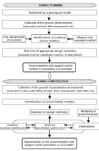
![Figure 1.3.1: Design process for tunnelling (sourced from [77])](https://thumb-eu.123doks.com/thumbv2/123doknet/11579438.298011/75.892.259.628.114.628/figure-design-process-for-tunnelling-sourced-from.webp)
![Figure 1.3.4: Structure of drained double-layer tunnel linings of Murgenthal tunnel (Switzerland) in hard rock (sourced from [81])](https://thumb-eu.123doks.com/thumbv2/123doknet/11579438.298011/79.892.279.607.112.421/figure-structure-drained-double-linings-murgenthal-switzerland-sourced.webp)
![Table 1.3.1: Parameters included in different numerical and function classification systems (sourced from [24])](https://thumb-eu.123doks.com/thumbv2/123doknet/11579438.298011/83.892.116.797.589.896/parameters-included-different-numerical-function-classification-systems-sourced.webp)

![Figure 2.2.4: Clustering results on the discontinuities data of the San Manuel cooper mine (data sourced from [130])](https://thumb-eu.123doks.com/thumbv2/123doknet/11579438.298011/114.892.130.787.110.398/figure-clustering-results-discontinuities-data-manuel-cooper-sourced.webp)
![Figure 2.2.5: Clustering results on the discontinuities data of the San Manuel cooper mine (data sourced from [130])](https://thumb-eu.123doks.com/thumbv2/123doknet/11579438.298011/115.892.126.788.709.1038/figure-clustering-results-discontinuities-data-manuel-cooper-sourced.webp)
