HAL Id: hal-01935073
https://hal.archives-ouvertes.fr/hal-01935073
Submitted on 5 Dec 2018
HAL is a multi-disciplinary open access archive for the deposit and dissemination of sci-entific research documents, whether they are pub-lished or not. The documents may come from teaching and research institutions in France or abroad, or from public or private research centers.
L’archive ouverte pluridisciplinaire HAL, est destinée au dépôt et à la diffusion de documents scientifiques de niveau recherche, publiés ou non, émanant des établissements d’enseignement et de recherche français ou étrangers, des laboratoires publics ou privés.
code framework for multi-modal and multi-dimensional
tomographic reconstruction
Thibaut Merlin, Simon Stute, Didier Benoit, Julien Bert, Thomas Carlier,
Claude Comtat, Marina Filipovic, Frédéric Lamare, Dimitris Visvikis
To cite this version:
Thibaut Merlin, Simon Stute, Didier Benoit, Julien Bert, Thomas Carlier, et al.. CASToR: a generic data organization and processing code framework for multi-modal and multi-dimensional to-mographic reconstruction. Physics in Medicine and Biology, IOP Publishing, 2018, 63 (18), pp.185005. �10.1088/1361-6560/aadac1�. �hal-01935073�
Processing Code Framework for Multi-Modal and
Multi-Dimensional Tomographic Reconstruction
Thibaut Merlin*
INSERM, UMR1101, LaTIM, CHRU de Brest, Brest, France *equally contributed
Simon Stute*
IMIV, CEA, INSERM, Universit´es Paris-Sud and Paris-Saclay, Service Hospitalier Fr´ed´eric Joliot, Orsay, France
*equally contributed
Didier Benoit
INSERM, UMR1101, LaTIM, Universit´e de Bretagne Occidentale, Brest, France
Julien Bert
INSERM, UMR1101, LaTIM, CHRU de Brest, Brest, France
Thomas Carlier
CHU Nantes & CRCINA INSERM UMR 1232 - CNRS ERL 6001 - Universit´e de Nantes, Nantes, France
Claude Comtat
IMIV, CEA, INSERM, Universit´es Paris-Sud and Paris-Saclay, Service Hospitalier Fr´ed´eric Joliot, Orsay, France
Marina Filipovic
IMIV, CEA, INSERM, Universit´es Paris-Sud and Paris-Saclay, Service Hospitalier Fr´ed´eric Joliot, Orsay, France
Fr´ed´eric Lamare
Univ. Bordeaux, INCIA, CNRS UMR 5287, Hˆopital de Bordeaux, France
Dimitris Visvikis
Abstract. In tomographic medical imaging (PET, SPECT, CT), differences in data acquisition and organization are a major hurdle for the development of tomographic reconstruction software. The implementation of a given reconstruction algorithm is usually limited to a specific set of conditions, depending on the modality, the purpose of the study, the input data, or on the characteristics of the reconstruction algorithm itself. It causes restricted or limited use of algorithms, differences in implementation, code duplication, impractical code development, and difficulties for comparing different methods. This work attempts to address these issues by proposing a unified and generic code framework for formatting, processing and reconstructing acquired multi-modal and multi-dimensional data.
The proposed iterative framework processes in the same way elements from list-mode (i.e. events) and histogrammed (i.e. sinogram or other bins) data sets. Each element is processed separately, which opens the way for highly parallel execution. A unique iterative algorithm engine makes use of generic core components corresponding to the main parts of the reconstruction process. Features that are specific to different modalities and algorithms are embedded into specific components inheriting from the generic abstract components. Temporal dimensions are taken into account in the core architecture.
The framework is implemented in an open-source C++ parallel platform, called CASToR (Customizable and Advanced Software for Tomographic Reconstruction). Performance assessments show that the time loss due to genericity remains acceptable, being one order of magnitude slower compared to a manufacturer’s software optimized for computational efficiency for a given system geometry. Specific optimizations were made possible by the underlying data set organization and processing and allowed for an average speed-up factor ranging from 1.54 to 3.07 when compared to more conventional implementations. Using parallel programming, an almost linear speed-up increase (factor of 0.85 times number of cores) was obtained in a realistic clinical PET setting. In conclusion, the proposed framework offers a substantial flexibility for the integration of new reconstruction algorithms while maintaining computation efficiency.
Keywords: PET, SPECT, CT, PET/CT, tomographic reconstruction, software, platform, image reconstruction, nuclear medicine, multimodal, multidimensionnal, dynamic
1. Introduction
In tomographic medical imaging, the interpretation of the underlying biological or pathological processes depends on the precision and the accuracy of the reconstructed images. Thus, tomographic image reconstruction is an essential step for the production of high quality images. Differences in data acquisition techniques have led to the development of many reconstruction methods adapted to the different imaging modalities such as Positron Emission Tomography (PET), Single-Photon Emission Computed Tomography (SPECT) and Computed Tomography (CT). These reconstruction techniques can differ in many aspects: the forward model (i.e. modelling of the direct problem), the optimization algorithm (i.e. algorithm used to solve the inverse problem related to tomographic image reconstruction), the modelling of the system matrix (i.e. use of specific projectors or system response models), the dimensionality of the image (e.g. spatial and temporal basis functions for dynamic studies) or the acquired data (e.g. physiological gating, energy windows), etc.
The large variety of data formats also increases the diversity of reconstruction methods, particularly in PET. The reduction of individual detection elements’ size, Time of Flight (TOF) measurements, as well as the increasing use of dynamic studies (for motion correction or tracer kinetics based analysis) all contribute to larger and sparser histogrammed data sets. As a consequence, the use of list-mode data (Snyder & Politte 1983, Parra & Barrett 1998) as a direct input to reconstruction algorithms has gained much interest in PET (Yan et al 2012). List-mode data provide access to the initial measurement precision in terms of spatial and temporal resolution, but they are not compatible with some reconstruction algorithms, such as fast analytical algorithms or algorithms with specific optimizations for sinogram data sets (Slambrouck et al 2015). The multitude of data formats and reconstruction methods makes the development of generic codes difficult and causes practical issues for assessing, disseminating, and comparing new techniques. Often, the use of a new reconstruction technique is restricted to a given imaging modality and data format, even if in principle it could be compatible with other modalities or data formats. When the same algorithm is implemented in several contexts, implementation details differ more or less and produce results that are not strictly comparable. PET, SPECT and CT use similar components for tomographic reconstruction (e.g. projection operators, iterative optimizations, geometry descriptions). The wide use of iterative methods in PET an SPECT and the re-emergence of iterative reconstruction in CT (Beister et al 2012) suggest that reconstruction software for these three modalities can be efficiently integrated into a unified iterative reconstruction framework.
In an attempt to address some of the aforementioned issues, several image reconstruction libraries have been proposed to the scientific community via open-source or free software. For emission tomography, STIR (Thielemans et al 2012) is an Open Source software providing a Multi-Platform Object-Oriented framework for image reconstruction in PET and SPECT as well as for the estimation of data correction
terms. QSPECT (Loudos et al 2010) is a package using MLEM (Maximum-Likelihood Expectation Maximization) or OSEM (Ordered-Subsets Expectation Maximization) for SPECT reconstruction. Several software packages have been proposed for CT, including RTK (Rit et al 2014) (an ITK-based package focused on cone-beam CT reconstruction), the Astra-Toolbox (van Aarle et al 2015) (a MATLAB and Python toolbox of high-performance GPU primitives for 2D and 3D tomography implementing a large number of algorithms including FBP, SIRT, SART, CGLS) and TIGRE (Biguri et al 2016) (a MATLAB and CUDA toolbox for fast and accurate 3D tomographic reconstruction providing a wide range of easy-to-use iterative algorithms for Cone Beam CT geometries and a beta version for parallel geometries). Other software packages have been proposed for multi-modal reconstruction such as NiftyRec (Pedemonte et al 2010) (a software for tomographic reconstruction using MATLAB and Python interfaces and providing GPU-accelerated reconstruction tools for PET, SPECT and CT) and Occiput (Pedemonte et al 2014) (a computing platform for tomographic reconstruction with tools for SPECT, PET and (partly) CT based on a Python library and a web-based interface enabling the use of the reconstruction tools on the cloud).
In this work, we present and evaluate a generic organization and processing framework for iterative tomographic reconstruction of multi-modal (PET, SPECT and CT) and multi-dimensional (static, dynamic, gated) data. This framework is new in the sense that it is entirely generic: (i) it makes use of a single iterative core algorithm able to process dynamic data sets for any modality and data type, (ii) this algorithm can use any projection model and optimization scheme, and (iii) any particular scanner geometry can be reconstructed. It has been implemented as an open-source C++ platform that makes extensive use of abstraction, favouring modularity and extensibility, while avoiding duplication and/or limited use of code. A special effort has been made in finding the best compromise between genericity and computational efficiency. This software is a research tool primarily dedicated to scientists wishing to reconstruct images from simulated or acquired data, from either clinical or experimental systems. Another potential interest of this software is to be used as a testing platform to help researchers in a specific field of tomographic reconstruction to compare their methods (e.g. projection operators, reconstruction algorithms) to other alternative algorithms.
The paper is organized as follows. Section 2 describes the concept of the framework and how it is implemented. Section 3 presents the performance of the implementation both in terms of computational efficiency and quantitative evaluation. The work is discussed in Section 4. Conclusion and perspectives are presented in Section 5.
2. Reconstruction framework
The proposed reconstruction framework is based on genericity in the sense of pure abstraction, and not according to the definition of generic programming in computer science (i.e. through templates). When applied to the scanner geometry (section 2.1) and the data (section 2.2) descriptions, the genericity allows the reconstruction, by
a single iterative core algorithm, of any kind of dynamic data sets acquired on any supported imaging modalities (PET, SPECT and CT), as described in section 2.3. This framework has been implemented in C++ as the Customized and Advanced Software for Tomographic Reconstruction (CASToR: http://castor-project.org). Some key aspects of the implementation are provided in section 2.4.
2.1. Generic system geometry
The geometry of the PET, SPECT and CT systems is assumed to be a set of indexed individual detection elements of rectangular shape (either crystals or detector pixels). A detection element is defined by its 3D Cartesian coordinates and an orientation vector providing the direction of the potential depth encoding. The current implementation supports PET, parallel- and convergent-beam SPECT (no pinhole collimator) and flat panel CT models. Each specific scanner is described in an input file with a predefined generic format. It can be either a text header file linked to a binary file containing the look-up-table (LUT) of geometrical characteristics of each detection element in the system (enabling complete flexibility), or a text file describing the overall geometry of the scanner, using the same terminology as in the GATE simulation platform (Jan et al
2011), with the corresponding LUT being automatically generated at run-time.
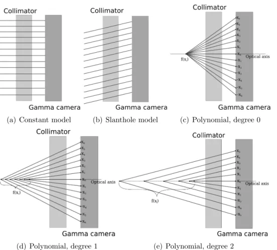
For PET systems, there is no a priori on the detectors’ layout. For SPECT systems, the position of the detection element is defined by the detector head angular and radial positions, and the index of the acquisition matrix element. The direction of the projection ray associated to a detection element depends on the modelling of the collimator. The current implementation of SPECT parallel and convergent collimators does not rely on the full modelling of the collimator within the projector. The collimator is instead characterized by an analytical model which allows the computation of the position of a focal point in the axial and transverse directions for each detection element. Several predefined models can be selected independently for the transverse and axial directions, in order to represent the behaviour of usual collimators, such as parallel-beam, fan-parallel-beam, cone-beam and slant-hole geometries. Figure 1 presents the different predefined SPECT collimator models currently considered within CASToR. A similar principle to that for SPECT has been applied to CT systems, where the position of the detection element is defined by the detector panel angular and radial positions, and the index of the detection element within the panel. The direction of the associated ray is then deduced from the position and shape of the source(s).
2.2. Generic data description
The idea behind the generic data description is to propose a single way of organizing the input data for all supported imaging modalities (PET, SPECT and CT), valid for both list-mode and histogram based formats. The data are represented as a list of generic events, supplied to the iterative core algorithm for reconstruction. This allows a unique implementation of the iterative core algorithm, without having to distinguish between
(a) Constant model (b) Slanthole model (c) Polynomial, degree 0
(d) Polynomial, degree 1 (e) Polynomial, degree 2
Figure 1. Predefined 2-D models for SPECT collimators. The model can differ between the transverse and the axial directions (e.g., fan-beam collimators). (a) Defines a parallel hole collimator. (b) Defines a one-parameter slanthole model where all the collimator septas are rotated according to a given angle. (c-e) A polynomial model is used to characterize mono-convergent and multi-convergent collimators. f (xi) is
the position of the focal point along the optical axis of the collimation model, as a function of the axial or transverse distance xi between the detection element i
and the optical axis. (c) Defines a mono-convergent collimator with a polynomial of degree zero, f (xi) = a0. (d) Defines a multi-convergent collimator with a linear
polynomial, f (xi) = a0+ a1xi. (e) Defines a multi-convergent collimator with a
quadratic polynomial, f (xi) = a0+ a1xi+ a2x2i.
the modalities or the data type (histogram or list-mode). This way and whenever appropriate (for example, for the ML-EM algorithm), the same implementation of an iterative algorithm can process both histogrammed and list-mode data.
A generic event consists either in the detection of one photon (SPECT, CT) or one coincidence (PET) for list-mode data, or, for histogrammed data, in the number of photons (SPECT, CT) or coincidences (PET), acquired within a given time frame, for a given projection bin or a given pair of crystals in coincidence, or for a cardiac and/or respiratory synchronization gate. Each event contains a time flag, information that identifies the scanner elements involved in the detection of the event (thus defining the projection ray in the scanning system, see section 2.1), as well as optional
meta-data (e.g. meta-data correction terms, time-of-flight). For instance, for PET, the position of the projection ray associated to an event is defined by the indices of the two detection elements in coincidence. In the case of transaxial or axial angular mashing, an event is associated to several pairs of detection elements, defining a group of projection rays. Regarding the implementation, the data file format consists of a text header file and a binary file containing all the aforementioned information.
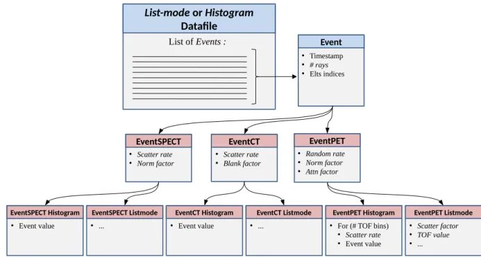
Each generic event is self-consistent and, based on the modality, contains all relevant information for a fully quantitative reconstruction, as presented in figure 2. For histogrammed data, there is no assumption on the organization of acquired data (no requirements whatsoever for the order of sinogram bins). This leads to a greater flexibility for handling any kind of scanner geometry. The amount of information included in the generic events is flexible; only a few items are mandatory. The reconstruction platform does not estimate the correction terms for the loss of sensitivity (attenuation in emission tomography, detector sensitivity) and for the background events (scattered events, random coincidences in PET). When required, these correction terms have to be provided by the user and included for each generic event.
EventPET • Random rate • Norm factor • Attn factor EventSPECT • Scatter rate • Norm factor EventCT Event • Timestamp • # rays • Elts indices List-mode or Histogram Datafile List of Events : • Scatter rate • Blank factor
EventSPECT Histogram EventSPECT Listmode EventCT Histogram EventCT Listmode EventPET Histogram EventPET Listmode
• Event value • ... • Event value • ... • For (# TOF bins)
● Scatter rate ● Event value
• Scatter factor • TOF value • ...
Figure 2. A generic data-file is viewed as a collection of generic Events. This allows a unique implementation of the iterative core algorithm at the highest level. At lower levels (e.g. when computing the system matrix elements associated to an event or when taking corrections into account), the events are ”specialized” depending on the modality (SPECT, CT or PET) and the data mode (histogram or listmode) specified in datafile meta-data. Italic formatting denotes optional attributes.
2.3. Generic iterative core algorithm
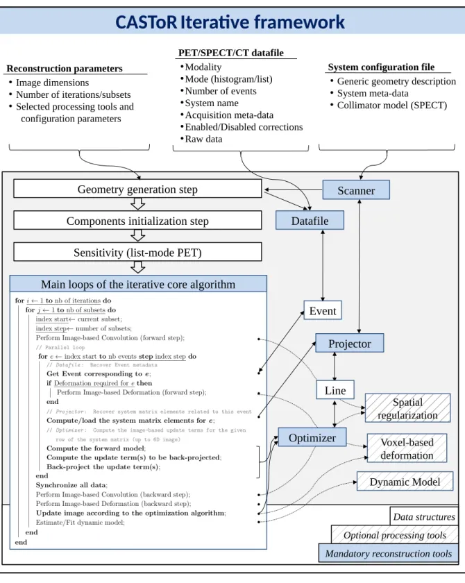
The reconstruction framework is designed to handle three levels of temporal dimensions: framing (related to tracer kinetics) and two levels of gating (related to respiratory and cardiac motions). These three temporal levels could be used simultaneously, resulting in 6-D images (not released yet). The main idea of the iterative core algorithm framework is that all events are processed separately as in list-mode based reconstructions, even for histogrammed data, thanks to the generic data description. This differs from usual histogram-based reconstruction implementations, where several histogram bins (typically, one projection view) are forward-projected or back-projected together. The events are supposed to be ordered with respect to their time flag, except when gating is used in which case the events are supposed to be grouped by gate. The main steps of the iterative core algorithm are sketched in figure 3. For any modality and any data type, a loop over the generic events is performed inside each iteration or each subset for algorithms using ordered subsets. This events loop consists of three main steps.
• Datafile: The content of the generic event is recovered from the datafile buffer. The time frame and gates indices are updated if needed and image deformations associated to motion correction are performed if required (not released yet). • Projector : The system matrix elements associated to this event (that is, one row of
the system matrix) are computed. This is done either by estimating these elements on-the-fly, projecting a ray through the image voxels, or by reading them from a precomputed system matrix (not released yet). The Projector does not perform the forward or the backward projection operations; they are computed within the Optimizer.
• Optimizer : According to the event, the associated system matrix elements and the current image estimate, the image-based update terms related to the optimization algorithm are computed. The Optimizer module embodies both the cost function and the numerical optimization algorithm. For any optimization algorithm, the Optimizer operations consists essentially in (i) computing the forward model along the event ray for the current image estimate (including all correction terms), (ii) back-projecting the sensitivity term for the provided event (only with histogram data), (iii) computing the update term(s) in the data space according to the optimization algorithm, and (iv) back-projecting the update term(s) in the image space along the event ray.
The recovery of the system matrix elements in the Projector step allows for the dissociation between their estimation and their use by the forward and backward projection operations performed in the Optimizer step. In most cases, matched forward and backward projectors are used. As a result, the projector algorithm is called only once, in contrast to many standard reconstruction algorithms, where the computation of the system matrix elements is performed separately for the forward projection and the backward projection. As it is the most costly operation in tomographic reconstruction, the potential speed loss induced by the loop on the individual events can be balanced
Dynamic Model Datafile Spatial regularization Voxel-based deformation
CASToR
Iterative framework
• Image dimensions
• Number of iterations/subsets • Selected processing tools and
configuration parameters
Reconstruction parameters
● Generic geometry description
• System meta-data
• Collimator model (SPECT)
System configuration file
• Modality • Mode (histogram/list) • Number of events • System name • Acquisition meta-data • Enabled/Disabled corrections • Raw data PET/SPECT/CT datafile Scanner
Main loops of the iterative core algorithm Components initialization step
Geometry generation step
Sensitivity (list-mode PET)
Projector Event
Optional processing tools Mandatory reconstruction tools
Data structures
Line
Optimizer
Figure 3. Scheme of the reconstruction framework. The algorithm describes the main loops of the iterative core algorithm over the iterations, the subsets, and the events. All mandatory instructions are written in bold (see text for details).
assessment). Choosing different forward and backward projector algorithms is also possible. In this case, the Projector computes the system matrix elements from both projection algorithms separately. The implementation of attenuated forward and backward projections for SPECT follows a dual loop on the voxels belonging to the projection ray, in order to take into account the varying attenuation from each emission point to the detection point. It thus needs an image of attenuation coefficients.
Iterative optimization algorithms require the computation of a sensitivity image, generated with a backward projection step over all possible (empty or not) detection elements. A sensitivity image is computed for each time frame, and for each gate if no physiological motion correction is performed. When reconstructing histogrammed data, the sensitivity image of the current subset is computed on-the-fly by the Optimizer. The already computed system matrix elements are reused, so the cost of the backward projection associated to the sensitivity image computation is much reduced. This strategy avoids precomputing and storing the sensitivity for each subset and allows for choosing a different number of subsets for each iteration. Also, for some algorithms (e.g. NEGML (Nuyts et al 2002, Slambrouck et al 2015)), the sensitivity image depends on the current image and thus cannot be precomputed. Each event is associated to a given frame/gate, and thus contributes to the sensitivity image of that frame/gate. In PET, the normalization and attenuation correction factors attached to the event are used. In SPECT, the provided attenuation map may be 6-D, so the one corresponding to the current frame/gate is used. Under motion correction, if the gate index changes, the related deformation field is applied to the sensitivity image (not released yet). When reconstructing list-mode data, the sensitivity image is precomputed before starting the iterations. The loop over all possible detection elements is based either on the sole characteristics of the scanner geometry description (thus ignoring detector efficiency effects), or on a user’s provided normalization datafile including the detector efficiency factors and optionally (for PET) the attenuation correction factors. A normalization datafile can be provided for each time frame. Otherwise, a 6-D attenuation map can be provided to correct for attenuation, for each time frame and each respiratory and cardiac gate. In case of motion correction (not released yet), the provided motion correction field is applied to each gate to compute the global sensitivity image. To ease the implementation of fully quantitative reconstruction algorithms for dynamic data, the following quantities are directly included in the system matrix elements: the calibration factor, the decay factors, the decay intensity, and the frame durations.
Optional processing tools can be used during the reconstruction. The current release includes image-based convolution (for applications such as Point-Spread Functions system resolution modelling). Future releases will include image processing algorithms (such as 4D filtering), image-based deformations (for applications such as rigid or elastic voxel-based motion correction), and estimation/fitting of dynamic models (for application such as kinetic modelling or temporal regularization). Like Projectors and Optimizers, the processing tools are all modular in order to be extensible and customizable.
2.4. CASToR architecture and implementation
The above-described reconstruction framework has been implemented as the open-source CASToR platform (http://castor-project.org). The key points of CASToR are genericity, flexibility, and modularity. Object-oriented programming in C++11 has been used to serve that purpose. The genericity has been integrated through extensive use of abstraction, namely by using abstract classes and pure virtual functions. Numerous comments as well as explicit names for variables and functions improve the readability of the code.
The code architecture is divided into several main components. Each component manages a global task; e.g. reading from data-files, managing scanner geometries, getting system matrix elements for a given ray, computing the update contribution of a ray with respect to an optimization algorithm. To do that, each component makes use of one or more abstract classes that generically represent the concept; e.g. a generic event, a generic scanner, a generic projector, a generic optimizer. Pure virtual functions are associated to generic actions onto those abstract classes; e.g. recover the content of an event, get the Cartesian coordinates of a detection element, compute the system matrix elements from a given ray and a given projector, compute the forward model associated to an event. These pure virtual functions are implemented by specific classes, inheriting from abstract classes; for instance:
• recover a PET event with the associated correction factors and crystal indices, • get the Cartesian coordinates of the two crystals from the associated PET scanner, • compute the system matrix elements of that ray using the Siddon projector, • compute the emission forward model associated to that event,
• compute the data or image update term with respect to the MLEM optimizer. In this framework, most of the code is generic, i.e. common to all imaging modalities, projector types, or optimizer algorithms. This generic code is implemented only once in the abstract classes. The few blocks of code, specific to a given modality or a given method, are found in the implementation of the pure virtual functions in the specific classes that inherit from the abstract classes. Those specific classes are viewed as plug-ins. This architecture has many advantages: (i) the addition of a new feature requires a minimal amount of code in a comprehensible manner, (ii) thanks to late binding, a new feature is readily compatible with all components of the reconstruction platform, unless an incompatibility is explicitly specified, (iii) there is no need to understand or modify the rest of the code while focusing on the development of a particular feature, (iv) the duplication of code is avoided.
However, genericity can be a source of inefficiency, so special care has been taken to optimize as much as possible the code efficiency. Firstly, object-oriented programming has been mainly used for code architecture and readability. Within this context, in order to avoid over-segmentation of the code, preference was given to the extensive use of memory pointers in the style of C programming. Secondly, the whole code benefits
from parallel programming. The main loop over the generic events (as described in section 2.3) has two levels of parallelism: one creating multiple instances of the program using the MPI library and one creating multiple threads (inside a MPI instance) using the OpenMP (Open Multi-Processing) API. Both can be used at the same time, typically with MPI distributing the load over several machines (by virtually splitting the data-file into consecutive pieces) and OpenMP distributing the load over several cores of each machine. A synchronization is then operated at the end of the events loop. OpenMP is also used in other parts of the code where the computational load is a burden. Thirdly, typical data-files can easily exceed several gigabytes. As the loop over the events is the central part of the generic algorithm, the best compromise between excessive disk reading and excessive memory usage has been implemented through the use of file mapping. This low-level programming allows to manage automatically the memory and cache usage for the best performance. Its implementation into CASToR works for both Unix and Windows based operating systems. Lastly, the precision of floating point numbers can be chosen at compilation time. The precision of sensitive operations and general operations can be customized, based on the architecture, on the amount of RAM, on user needs, on the precision of input data files and of image matrices.
This paper is based on CASToR version 2.0. TOF-PET list-mode and histogrammed data, as well as SPECT and CT histogrammed data can be reconstructed within this version. Implemented ray-driven projectors include the original Siddon’s algorithm (Siddon 1985), an accelerated version of Siddon’s (Jacobs et al 1998), Joseph’s algorithm (Joseph 1982) and the distance-driven algorithm (Man & Basu 2004). Implemented optimizers include MLEM (Shepp & Vardi 1982) for both emission (list-mode and histogrammed data) and transmission (histogram) data, the Landweber’s (Landweber 1951) for both emission and transmission histogrammed data, MLTR (Nuyts et al 1998, Slambrouck & Nuyts 2014) for transmission histogrammed data, AML (Byrne 1999) and NEGML (Nuyts et al 2002, Slambrouck et al 2015) for emission histogrammed data.
3. Evaluation results
3.1. Computing performance assessment
All the experiments in this section were repeated 5 times and averaged to get a more robust estimation of execution times and efficiencies. At worst, the standard-deviation reached a few percent. Due to its generic nature, CASToR is not intended to be as fast as a reconstruction software optimized and dedicated to a particular system. The computing performance of CASToR and the Biograph 6 TruePoint TrueV PET system (Siemens Healthcare, Erlangen, Germany) manufacturer’s software (e7-tools, version 7) were compared on the same operating computer (Intel i5-3470 processor, four 3.20 GHz cores). A standard single bed position data set of 336 × 336 × 559 sinogram bins was reconstructed using 28 subsets. The manufacturer’s software is highly optimized with
respect to the specific system geometry by matching the sinogram bin size to the voxel width (Hong et al 2007). The reconstruction is thus always performed with 336 × 336 × 109 voxels of roughly 2 × 2 × 2 mm3. If a different sampling is used (e.g. voxels
of 4 × 4 × 2 mm3 for a whole-body reconstruction), an interpolation is performed at
the end of the reconstruction. For a fair comparison, the native sampling was also used for the CASToR reconstruction, using the Siddon projector (Siddon 1985). The 4 cores of the processor were used by both software. In addition, the manufacturer’s software makes use of vectorial instructions from the processor, leading to an additional maximal speed-up factor of 4 (Hong et al 2007). Vectorial computing is not currently supported within CASToR. Despite this, CASToR took an average of 200.4 seconds per iteration compared to 19.5 seconds per iteration (an order of magnitude less) for the manufacturer’s software.
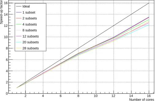
The scalability of the parallel implementation of CASToR was also assessed. Figure 4 shows the speed-up factors achieved with respect to the number of cores used on a dual Intel E5-2650 (2 sockets × 8 cores) at 2.00 GHz. A PET non-TOF histogram data set from the SIGNA PET/MR system (GE Healthcare, Wakesha, WI, USA) corresponding to a single bed position (162 · 106 bins) was reconstructed using
different numbers of subsets. The image sampling was 200 × 200 × 84 voxels of 3 × 3 × 3 mm3, covering a field-of-view of 600 × 600 × 252 mm3. The projector
from (Joseph 1982) was used, with an image-based PSF modelled by an isotropic 3D Gaussian of 4 mm FWHM. The width of the convolution kernel was set to three standard deviations of the Gaussian, leading to a kernel of 5 × 5 × 5 voxels. Note that 3 convolutions are performed for each update: one applied to the forward image, one applied to the backward correction image and one to the sensitivity image which is computed for each subset. For a maximum of 16 parallel threads, the computation time for one iteration with 28 subsets was 237 seconds (224 seconds without image-based PSF modelling). For a given number of threads, the speed-up factor with respect to a single thread seems to depend on the number of subsets (between 12.2 and 13.5), though not in a simple way (see figure 4). Globally, the efficiency factor (i.e. speed-up factor over the number of cores) is 0.85 ± 0.04. This value is due to the growing amount of memory needed for the back-projection to be thread-safe. We suspect that the small variability of the efficiency with respect to the number of cores or subsets is directly related to the computer architecture (i.e. numbers of chipsets, cores, memory channels and links between them, as well as CPU cache).
As explained in section 2.3, CASToR uncouples the computation of the system matrix elements for a given projector algorithm from their use for the actual forward and backward projections. When using the same projector for forward and backward projections, these system matrix elements can be reused, avoiding their computation twice for a given ray. While allowing for global genericity, this feature also contributes to reducing the computational burden associated with a generic software. This feature of CASToR was compared to a version where the forward and backward projections are computed and used on-the-fly, as is generally the case in more conventional
2 4 6 8 10 12 14 16 Number of cores 0 2 4 6 8 10 12 14 16 Speed-up factor Ideal 1 subset 2 subsets 4 subsets 8 subsets 12 subsets 20 subsets 28 subsets
Figure 4. Speed-up factor with respect to the number of cores used for the computation, for different numbers of subsets. Results obtained for a PET non-TOF histogram data set from the SIGNA PET/MR (162 · 106sinogram bins) reconstructed
into 200 × 200 × 84 voxels of 3 × 3 × 3 mm3, using the projector from (Joseph 1982)
and an image-based PSF (3D Gaussian of 4 mm FWHM).
implementations. The speed-up factor of the standard CASToR version with respect to the on-the-fly version was obtained with respect to different parameters as described below.
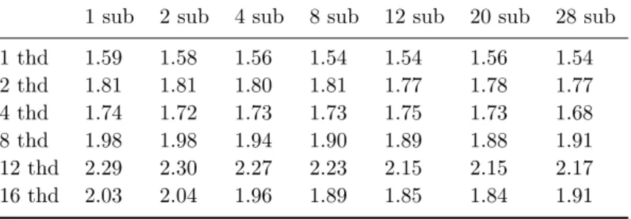
The influence of the number of voxels, subsets and threads was assessed with the same PET non-TOF histogram data set used for the scalability assessment (figure 4), using Joseph’s projector and no resolution modelling. Table 1 presents the speed-up factor for different numbers of threads and subsets, using an image of 200 × 200 × 84 voxels of 3 × 3 × 3 mm3. The speed-up factor ranges from 1.54 to 2.30. The number of
subsets has only a slight influence whereas the number of threads has a greater influence. The influence of the voxel size was assessed while maintaining the same field-of-view, using 16 threads and 28 subsets. For isotropic voxel’s size from 1 mm to 4 mm, the speed-up factor ranges from 1.74 to 1.93. The voxel size has only a small influence. The relationships between speed-up factors and reconstruction parameters were rather complex and did not show any self-evident trends.
Using the same data set again, the influence of the projector algorithm was assessed, without resolution modelling. The implementations of Siddon’s (Siddon 1985), Joseph’s (Joseph 1982) and Distance-Driven (Man & Basu 2004) projectors for histogrammed data with and without TOF and list-mode data with TOF were tested. Table 2 presents the speed-up factors for these different projectors, using 16 threads, 28 subsets and an image of 200 × 200 × 84 voxels of 3 × 3 × 3 mm3. The projector has
reflect the fact that the average number of voxels contributing to a ray is the smallest for Siddon’s, followed by Joseph’s and Distance-Driven projector. Speed-up factors higher than 2 are most probably caused by a more efficient use of CPU cache memory when performing forward and backward projections directly one after the other using already pre-computed system matrix elements.
Table 1. Speed-up factor for the standard CASToR version with respect to the on-the-fly version, varying the numbers of threads and subsets. Results obtained for a General Electric SIGNA PET/MR non-TOF histogrammed data set reconstructed using the Joseph projector and no resolution modelling in an image of 200 × 200 × 84 voxels of 3 × 3 × 3 mm3. For display purposes, the word subset is abbreviated sub
and the word thread is abbreviated thd.
1 sub 2 sub 4 sub 8 sub 12 sub 20 sub 28 sub 1 thd 1.59 1.58 1.56 1.54 1.54 1.56 1.54 2 thd 1.81 1.81 1.80 1.81 1.77 1.78 1.77 4 thd 1.74 1.72 1.73 1.73 1.75 1.73 1.68 8 thd 1.98 1.98 1.94 1.90 1.89 1.88 1.91 12 thd 2.29 2.30 2.27 2.23 2.15 2.15 2.17 16 thd 2.03 2.04 1.96 1.89 1.85 1.84 1.91
Table 2. Speed-up factor for the standard CASToR version with respect to the on-the-fly version, varying the projector algorithm. Results obtained for a SIGNA PET/MR data set reconstructed as a list-mode or histogram with or without TOF. Sixteen threads and 28 subsets were used, an image of 200 × 200 × 84 voxels of 3 × 3 × 3 mm3 and no resolution modelling.
List-mode TOF Histogram TOF Histogram non-TOF Siddon 2.16 2.00 2.50
Joseph 1.77 1.75 1.90 Distance-Driven 2.29 1.80 3.07
3.2. Quantitative evaluation
Figure 5 presents OSEM reconstructions (2 iterations and 28 subsets) of a whole-body [18F]-FDG TOF-PET data set acquired on a SIGNA PET/MR system, using
the manufacturer software and CASToR. This data set takes into account all required corrections for quantitative imaging in Bq/cc (attenuation, scatter, random, normalization, radionuclide, timing and calibration). The Joseph’s projector (Joseph 1982) was used within CASToR. Profiles through an axial slice show good agreement between the different reconstructions. A measure of contrast defined as the ratio of the mean activity inside tumour and liver regions of interest (ROI), and a measure of noise defined as the standard-deviation of voxels values inside the liver ROI, are also provided in figure 5.
0 100 200 300 400 500 Transverse position [mm] 0 2000 4000 6000 8000 10000 12000 14000 Activity [Bq/cc]
Manufacturer ToF recons. CASToR list-mode ToF recons. CASToR histogram ToF recons.
Figure 5. Whole-body [18F]-FDG data set acquired on a SIGNA PET/MR system
with (top) manufacturer (middle) CASToR list-mode and (bottom) CASToR histogram reconstructions including TOF information (see text for details). The horizontal lines in the axial slices show the location of the transverse profiles and the ellipses correspond to the liver ROI. Arrows in the coronal images show the tumour for which the contrast was calculated. Data courtesy of Dr. Micha¨el Soussan.
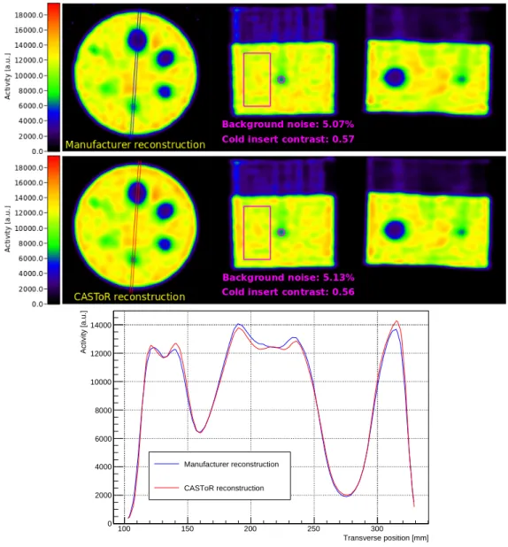
Figure 6 presents OSEM reconstructions (4 iterations and 15 subsets) of a SPECT
99mTc Jaszczak phantom data set acquired on a Symbia Intevo SPECT/CT dual-head
system (Siemens Healthcare, Erlangen, Germany), using the manufacturer’s software and CASToR. Parallel collimators were used. Attenuation and scatter corrections were included. The manufacturer’s Flash 3DT M software was used. This software uses
a non-stationary modelling of the PSF depending on the distance to the collimator. For comparison purposes, CASToR uses the Siddon projector (Siddon 1985) with a stationary PSF modelled as a 3D isotropic Gaussian of 11 mm FWHM. Units are arbitrary as absolute quantification was not available on the system. Images were scaled relatively by matching ROI measurements made into uniform slices. Profiles through an axial slice show good agreement between the two different reconstructions. A measure of contrast defined as the ratio of the mean activity inside the smallest cold insert and the background ROIs, and a measure of noise defined as the standard-deviation of voxels values inside the background ROI, are also provided in figure 6.
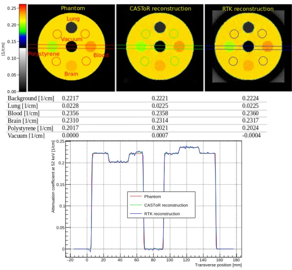
Figure 7 presents a cone-beam CT (CBCT) reconstruction of a simulated cylinder (15 cm diameter) including 5 cylindrical inserts (2.5 cm diameter). The scene is made of air, the cylinder of water, the central insert of vacuum and the 4 peripheral inserts are made of lung, blood, brain and polystyrene materials respectively. The in-house simulation software starts with a random generation of 52 keV X-rays (position and momentum) inside a rectangular source (0.6 × 1.2 mm2). Each photon is then projected through the phantom and a Beer-Lambert draw evaluates if the photon escapes the phantom or not. The photon is finally projected onto the rectangular detector (651 × 651 pixels of 0.444 × 0.444 mm2 without gaps) where a random efficiency between 0.9
and 1.0 is assigned to each pixel. The source-to-axis and detector-to-axis distances are 1049 and 602 mm respectively. The phantom and blank scans are simulated with the same number of primaries. An average of 9.5·103photons per pixel were recorded for the
blank scan, and 900 projections over 360◦ were simulated for the phantom. Scattered events were added by convolving the primaries escaping the phantom with an arbitrary kernel and adding Poisson noise. The scatter to primary (escaping the phantom) ratio was set to 0.3 (Sisniega et al 2013). The reconstruction was based on the maximum-likelihood gradient-ascent algorithm for transmission tomography (MLTR) (Slambrouck & Nuyts 2014) with 30 iterations and 80 subsets. A custom relaxation parameter was applied to the update step, starting at 4 and linearly decreasing to 3 over the successive updates. A non-negativity constraint was applied after each update. The distance driven projector (Man & Basu 2004) was used. A 0.75 mm FWHM 3D Gaussian post-filter was applied. For comparison, the simulated data were also reconstructed with the RTK software (Rit et al 2014), using the Feldkamp-David-Kress algorithm (Feldkamp et al 1984) and a Hann filter (at Nyquist cut-off frequency). A quantitative comparison with respect to real CT data was not feasible due to the unavailability of scatter correction terms from the scanner’s software. A profile through an axial slice of the phantom and the reconstructed images shows an accurate quantification of the attenuation coefficients. Exponential edge-gradient artefacts are visible over the lines common
100 150 200 250 300 Transverse position [mm] 0 2000 4000 6000 8000 10000 12000 14000 Activity [a.u.] Manufacturer reconstruction CASToR reconstruction
Figure 6. 99mTc Jaszczak phantom data set acquired on a Symbia Intevo SPECT/CT dual-head system (parallel collimators) with (top) manufacturer and (bottom) CASToR reconstructions (see text for details). The horizontal lines in the axial slices centred on the cold spheres show the location of the transverse profile. The rectangles and circles in the coronal slices respectively correspond to the background and cold sphere ROIs. The upper part of the phantom includes an insert with cold rods. Units are arbitrary as absolute quantification was not available on the system. Images were scaled relatively.
to anti-aligned inserts with high density variations (Joseph & Spital 2013). Mean attenuation coefficients measured inside multiple ROIs are also provided in figure 7. Noise was not measured since reconstruction algorithms are entirely different.
The data presented in this section were used to build the CASToR benchmarks, available on the website‡. These benchmarks include run-scripts to automatically launch the reconstruction with predefined settings and to compare the resulting image to a ‡ http://www.castor-project.org/benchmarksv2
20 − 0 20 40 60 80 100 120 140 160 180 Transverse position [mm] 0 0.05 0.1 0.15 0.2 0.25
Attenuation coefficient at 52 keV [1/cm]
Phantom
CASToR reconstruction RTK reconstruction
Figure 7. CASToR reconstruction of a CBCT simulated data set (see text for details) with (left) the original phantom, (middle) CASToR reconstruction and (right) RTK reconstruction. The horizontal lines in the axial slices show the location of the transverse profiles. The small circles show the background ROIs. For inserts, the same ROI size was used.
provided reference image. They can be used either by users to test the code or by developers to track down any potential drift in terms of quantification or performance.
4. Discussion
Besides all the advantages covered in this paper, genericity has intrinsic limitations discussed in the following paragraphs: (i) the computation time that may be increased, (ii) the need for a unified data format that requires conversion of input data, and (iii) the methods based on specific geometry organization that may be hardly implementable.
A special effort has been put in finding the best compromise between genericity and computational efficiency. A key feature consists in uncoupling the computation of the system matrix elements from their use for the actual forward and backward projections, for each ray. When using matched projectors, the computed system matrix elements are
used for both forward and backward projections, without having to compute them twice. Speed-up factors ranging from 1.54 to 3.07 (depending on the reconstruction parameters) were obtained when compared to a more conventional implementation in which the system matrix elements are computed within both forward and backward projections. Compared to a manufacturer’s software highly optimized for the Biograph True Point TrueV PET system, CASToR was one order of magnitude slower in the same typical setting. Two levels of parallelism in CASToR allows to spread the computational burden over architectures of multiple computers equipped with multi-core CPUs. In a realistic clinical PET setting, a mean efficiency factor (speed-up factor over the number of cores used) of 0.85 was obtained on a dual Intel E5-2650 computer (16 cores). The image array on which the backward projection is applied is duplicated as many times as the number of threads in order to be thread-safe (i.e. to avoid conflicts when the same voxel is updated by multiple threads at the same time). So for computers with even more physical cores, the efficiency factor may drop for really high number of threads for two reasons. First, the access to the large amount of RAM may slow down due to bus bandwidth. Second, the required summation of these duplicated image arrays at the end of the events loop may become significant with respect to the acceleration of this loop. When splitting the computation over several computers using MPI, a limitation can be the network speed. Indeed, the datafile will usually be located on a shared file system from which each computer will read a portion of it through the network. Then, as for multi-threading, the image arrays on which the backward projection is applied have to be shared through the network amongst all computers at the end of the events loop. Otherwise, the summation of these image arrays may only be a limitation with large numbers of computers, which is rarely the case. The limits will strongly depend on the hardware and should be determined for each tomographic reconstruction setting. While the reported performances reflect a fair balance between genericity and efficiency, the computational burden may be further reduced by introducing specific hardware techniques such as with graphical processing units (GPUs), though it might partly compromise the genericity (Benoit et al 2017). Future work will focus on using vectorial instructions intrinsically available on current CPU architectures.
CASToR uses a dedicated input data file format. This was a requirement in order to be able to process and reconstruct any type of tomographic data. The first consequence is that all correction terms have to be part of the input data for absolute quantitative imaging. Thus, users must be able to get or compute these corrections independently from CASToR. The second consequence is that, in order to use CASToR, simulated or real data have to be converted into this dedicated file format. A growing collection of conversion tools is distributed on the website for that purpose (including tools for GATE simulated data and data acquired on real scanners). If such a tool is not available, users must get all the necessary information from the scanner and understand how to match data projection rays to the physical elements of the scanner.
CASToR can easily reconstruct data from unusual scanner geometries where the use of standard sinograms is impossible (e.g. box-shape scanners or scanners with huge gaps). For the same reason, methods that exploit a specific geometric data organization (e.g. data grouped by projection views) may be hardly implementable within CASToR. The implementation of the RAMLA algorithm (Browne & de Pierro 1996) would need a specific events ordering within the datafile, matching the way the loop over events is performed, in order to be valid. Sinogram-based PSF modeling in PET cannot be implemented using simple sinogram convolutions. The same applies for distance-dependent image-based collimator-detector response modelling in SPECT. In CASToR, such resolution modelling techniques can be implemented directly within the Projector but would be intrinsically less efficient. Finally, some computation optimizations using scanner symmetries are almost impossible due to the generic framework.
Pinhole SPECT has not been implemented in CASToR yet. Single pinhole is simple and straightforward to implement as it is very similar to already implemented SPECT systems (see figure 1). Multi-pinhole is different from all other modalities in the sense that several rays can be associated to each event (one detection element can be paired with several holes). However, it is similar to the case of PET with compression (i.e. axial or azimuthal mashing) that CASToR currently manages by averaging end points positions of the rays contributing to the event in order to extract a single ray. This implementation can easily be adapted to generic multi-pinhole SPECT scanners by replacing the averaging with an independent call to the projection algorithm for each ray.
5. Conclusion and perspectives
This paper presents a generic data organization and processing code framework for multi-modal and multi-dimensional iterative tomographic reconstruction. It makes use of a single iterative core algorithm able to process dynamic data sets for any supported modality (PET, SPECT and CT) and data types (histogrammed or list-mode data). It can use any projection model, optimization scheme, and any specific scanner geometry. It has been implemented in the open-source object-oriented C++ CASToR platform, which makes extensive use of abstraction, favouring modularity and extensibility, while avoiding duplication and/or limited use of code.
This work refers to CASToR version 2.0, available on the website (http://castor-project.org) along with detailed documentation about its use and implementation. Extensive quantitative evaluation was conducted for PET, SPECT (no pinhole) and CT static reconstructions, from which few examples were presented in this work. All dynamic aspects, including the management of physiological and patient motion correction, the use of custom time basis functions and direct parametric imaging, are currently undergoing careful evaluation and will be released as part of a future version. Maximum a posteriori and penalized reconstruction algorithms are also under development and validation.
CASToR has been designed to be a community platform, so the project and its utility depend on the participation of the research community. We aimed at making the implementation of new methods as straightforward as possible, which makes participation and collaboration easier.
6. Acknowledgements
This work was partly funded by the French program Infrastructure d’avenir en Biologie Sant´e ANR-11-INBS-0006 (France Life Imaging). The authors thank both Valentin Vielzeuf and Ma¨el Millardet for their contributions into making simulated and acquired data compatible with the CASToR project. The authors also thank Lionel Kallou for its kind assistance in acquiring and processing the SPECT/CT data.
References
Beister M, Kolditz D & Kalender W A 2012 Iterative reconstruction methods in X-ray CT Physica Medica 28(2), 94 – 108.
Benoit D, Merlin T, Bert J, Carlier T, Lamare F & Visvikis D 2017 CT iterative reconstruction within the CASToR platform using GPU architecture IEEE Medical Imaging Conference (poster presentation).
Biguri A, Dosanjh M, Hancock S & Soleimani M 2016 TIGRE: a MATLAB-GPU toolbox for CBCT image reconstruction Biomedical Physics & Engineering Express 2(5), 055010.
Browne J & de Pierro A B 1996 A row-action alternative to the em algorithm for maximizing likelihood in emission tomography IEEE Transactions in Medical Imaging 15, 687–699.
Byrne C 1999 Iterative projection onto convex sets using multiple Bregman distances Inverse Problems 15(5), 1295–1313.
Feldkamp L, Davis L C & Kress J W 1984 Practical cone-beam algorithm Journal of the Optical Society Of America A 1, 612–619.
Hong I K, Chung S T, Kim H K, Kim Y B, Son Y D & Cho Z H 2007 Ultra Fast Symmetry and SIMD-Based Projection-Backprojection (SSP) Algorithm for 3-D PET Image Reconstruction IEEE Transactions on Medical Imaging 26(6), 789–803.
Jacobs F, Sundermann E, Sutter B D, Christiaens M & Lemahieu I 1998 A fast algorithm to calculate the exact radiological path through a pixel or voxel space Journal of Computing and Information Technology 6, 89–94.
Jan S, Benoit D, Becheva E, Carlier T, Cassol F, Descourt P, Frisson T, Grevillot L, Guigues L, Maigne L, Morel C, Perrot Y, Rehfeld N, Sarrut D, Schaart D R, Stute S, Pietrzyk U, Visvikis D, Zahra N & Buvat I 2011 GATE V6: a major enhancement of the GATE simulation platform enabling modelling of CT and radiotherapy Physics in Medicine & Biology 56(4), 881–901.
Joseph P M 1982 An improved algorithm for reprojecting rays through pixel images IEEE Transactions on Medical Imaging 1, 192–196.
Joseph P M & Spital R D 2013 The exponential edge-gradient effect in x-ray computed tomography Physics in Medicine and Biology 26(3), 473–487.
Landweber L 1951 An Iteration Formula for Fredholm Integral Equations of the First Kind American Journal of Mathematics 73, 615–624.
Loudos G K, Papadimitroulas P, Zotos P, Tsougos I & Georgoulias P 2010 Development and evaluation of QSPECT open-source software for the iterative reconstruction of SPECT images Nuclear Medicine Communications 31(6), 558,566.
Man B D & Basu S 2004 Distance-driven projection and backprojection in three dimensions Physics in Medicine and Biology 49, 2463–2475.
Nuyts J, Man B D, Dupont P, Defrise M, Suetens P & Mortelmans L 1998 Iterative reconstruction for helical ct: A simulation study Physics in Medicine and Biology 43, 729737.
Nuyts J, Stroobants S, Dupont P, Vleugels S, Flamen P & Mortelmans L 2002 Reducing loss of image quality due to the attenuation artifact in uncorrected pet whole body images Journal of Nuclear Medicine 43, 10541062.
Parra L & Barrett H H 1998 List-mode likelihood: Em algorithm and image quality estimation demonstrated on 2-d pet IEEE Transactions on Medical Imaging 17(2), 228–235.
Pedemonte S, Bousse A, Erlandsson K, Modat M, Arridge S, Hutton B F & Ourselin S 2010 in ‘IEEE Nuclear Science Symposuim Medical Imaging Conference’ pp. 2657–2661.
Pedemonte S, Catana C & Van Leemput K 2014 in ‘Bayesian and grAphical Models for Biomedical Imaging: First International Workshop, BAMBI 2014, Cambridge, MA, USA, September 18, 2014, Revised Selected Papers’ Springer International Publishing Cham pp. 61–72.
Rit S, Oliva M V, Brousmiche S, Labarbe R, Sarrut D & Sharp G C 2014 The Reconstruction Toolkit (RTK), an open-source cone-beam CT reconstruction toolkit based on the Insight Toolkit (ITK) Journal of Physics: Conference Series 489(1), 012079.
Shepp L A & Vardi Y 1982 Maximum Likelihood Reconstruction for Emission Tomography IEEE Transactions on Medical Imaging 1(2), 113–122.
Siddon R 1985 Fast calculation of the exact radiological path for a three-dimensional ct array Medical Physics 12, 252–255.
Sisniega A, Zbijewski W, Badal A, Kyprianou I S, Stayman J W, Vaquero J J & Siewerdsen J H 2013 Monte carlo study of the effects of system geometry and antiscatter grids on cone-beam ct scatter distributions Medical Physics 40(5), 051915.
Slambrouck K V & Nuyts J 2014 Reconstruction scheme for accelerated maximum likelihood reconstruction: The patchwork structure IEEE Transactions on Nuclear Science 61(1), 173– 181.
Slambrouck K V, Stute S, Comtat C, Sibomana M, van Velden F H P, Boellaard R & Nuyts J 2015 Bias Reduction for Low-Statistics PET: Maximum Likelihood Reconstruction With a Modified Poisson Distribution IEEE Transactions on Medical Imaging 34(1), 126–136.
Snyder D L & Politte D G 1983 Image reconstruction from list-mode data in an emission tomography system having time-of-flight measurements IEEE Transactions on Nuclear Science 30(3), 1843– 1849.
Thielemans K, Tsoumpas C, Mustafovic S, Beisel T, Aguiar P, Dikaios N & Jacobson M W 2012 STIR: software for tomographic image reconstruction release 2 Physics in Medicine & Biology 57(4), 867–883.
van Aarle W, Palenstijn W J, Beenhouwer J D, Altantzis T, Bals S, Batenburg K J & Sijbers J 2015 The ASTRA Toolbox: A platform for advanced algorithm development in electron tomography Ultramicroscopy 157(Supplement C), 35 – 47.
Yan J, Planeta-Wilson B & Carson R E 2012 Direct 4-D PET List Mode Parametric Reconstruction With a Novel EM Algorithm IEEE Transactions on Medical Imaging 31(12), 2213–2223.
![Figure 5. Whole-body [ 18 F]-FDG data set acquired on a SIGNA PET/MR system with (top) manufacturer (middle) CASToR list-mode and (bottom) CASToR histogram reconstructions including TOF information (see text for details)](https://thumb-eu.123doks.com/thumbv2/123doknet/11570412.297501/17.918.151.732.125.930/figure-acquired-manufacturer-castor-histogram-reconstructions-including-information.webp)