HAL Id: hal-01292135
https://hal.archives-ouvertes.fr/hal-01292135
Submitted on 30 Jun 2016
HAL is a multi-disciplinary open access
archive for the deposit and dissemination of
sci-entific research documents, whether they are
pub-lished or not. The documents may come from
teaching and research institutions in France or
abroad, or from public or private research centers.
L’archive ouverte pluridisciplinaire HAL, est
destinée au dépôt et à la diffusion de documents
scientifiques de niveau recherche, publiés ou non,
émanant des établissements d’enseignement et de
recherche français ou étrangers, des laboratoires
publics ou privés.
GinFlow: A Decentralised Adaptive Workflow Execution
Manager
Javier Rojas Balderrama, Matthieu Simonin, Cédric Tedeschi
To cite this version:
Javier Rojas Balderrama, Matthieu Simonin, Cédric Tedeschi. GinFlow: A Decentralised Adaptive
Workflow Execution Manager. 30th IEEE International Parallel & Distributed Processing Symposium,
May 2016, Chicago, United States. �hal-01292135�
GinFlow: A Decentralised Adaptive Workflow
Execution Manager
Javier Rojas Balderrama
Signal and Image Processing Laboratory (LTSI) Inserm – Université de Rennes 1, France
Matthieu Simonin
†Cédric Tedeschi
‡Institute for Research in IT and Random Systems (IRISA)
† Inria – ‡ Université de Rennes 1, France
{firstname.lastname}@inria.fr
Abstract—Workflow-based computing has become a dominant paradigm to design and execute scientific applications. After the initial breakthrough of now standard workflow management systems, several approaches have recently proposed to decen-tralise the coordination of the execution. In particular, shared space-based coordination has been shown to provide appropriate building blocks for such a decentralised execution. Uncertainty is also still a major concern in scientific workflows. The ability to adapt the workflow, change its shape and switch for alternate scenarios on-the-fly is still missing in workflow management systems. In this paper, based on the shared space model, we firstly devise a programmatic way to specify such adaptive workflows. We use a reactive, rule-based programming model to modify the workflow description by changing its associated direct acyclic graph on-the-fly without needing to stop and restart the execution from the beginning. Secondly, we present the GinFlow middleware, a resilient decentralised workflow execution manager implementing these concepts. Through a set of deployments of adaptive workflows of different characteristics, we discuss the GinFlow performance and resilience and show the limited overhead of the adaptiveness mechanism, making it a promising decentralised adaptive workflow execution manager.
I. INTRODUCTION
Simulation experiments have become the dominant
paradigm for research in many scientific domains. These simulations often relies on the composition of functional building blocks to solve compute-intensive problems. Such compositions are referred as scientific workflows. Formally, a workflow can be represented as a graph in which each node is a function, or service and each edge is data or a control dependency between services. Workflow management systems such as Taverna [1], Kepler [2] and MOTEUR [3] have focused on providing tools to design and execute scientific workflows with a high level of abstraction.
In this paper, we present a decentralised execution work-flow engine. It is built upon a series of works in workwork-flow research which focus on tackling the limitations of centralised engines through the direct cooperation between services. De-centralisation brings about a better scalability and reliability of the execution. In particular, works such as [4], [5] propose mechanisms to make effective the collaboration by means of a shared space containing the information about the workflow. The output of scientific workflows (and their potential intermediary data) is rather hard to characterise prior to ex-ecution. This uncertainty comes together with the scientist’s requirement to be able to explore different scenarios during enactment, as different intermediary results may call for a
different versions of the subsequent workflow. Scientific work-flows are meant to support fields where variability and uncer-tainty is largely present during experimentation. Consequently, workflow management systems should be able to propose ways to specify and execute alternative workflow scenarios, each one getting enabled only if some specific event is detected at run time, such as a hardware failure or, more commonly the non-satisfaction of a specific property or partial data results. This would provide a new chance to obtain meaningful results without having to restart the whole workflow. At run time, this alternative workflow should be triggered on-the-fly by the workflow engine, in a transparent way for the user, saving time and computer power.
Firstly, we present a programmatic way to specify ex-ception handling and alternate workflow scenarios, based on a reactive, rule-based programming paradigm. We show how this specification can get enacted over a decentralised architecture, which relies on a shared space to exchange information among services. Secondly, we introduce the design of GinFlow, which implements these concepts on top of the Kafka1 and ActiveMQ2 middleware for communications, and Mesos [6] for scheduling. Thirdly, we detail the results of an extensive experimental campaign of GinFlow, focusing on its scalability and resilience in different settings. This campaign was conducted on the Grid’5000 platform [7] and made use of the Montage workflow.3
In Section II, we present the architectural and programming framework we rely on. In Section III, we describe program-ming abstractions allowing to modify the workflow on-the-fly. In Section IV, the GinFlow middleware, in which these concepts have been implemented, is introduced. Experimental results of GinFlow in terms of performance, adaptiveness, and resilience are detailed in Section V. Related works are dis-cussed in Section VI. Finally, Section VII draws a conclusion.
II. SHARED-SPACE BASED COORDINATION
GinFlow was inspired by conceptual works intending to decentralise the execution of workflows [5]. These works rely on the use of a shared space to coordinate services involved in the enactment. Services of a workflow can be seen as agents reading and writing information in a shared data space. Such
1http://kafka.apache.org/ 2http://activemq.apache.org/ 3http://montage.ipac.caltech.edu/
a programming model takes its roots in languages such as Linda [8] and KLAIM [9].
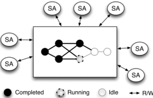
The architecture is depicted in Fig. 1. As detailed in [5], the shared space contains the description of the workflow. During enactment, each time the execution moves forward, this description is updated so as to reflect the execution progress. The service agents (SAs) are essentially workers that encapsulate the invocation of the services. This encapsulation includes an engine able to read, interpret and update the information contained in the shared space. For instance, when a SA completes the invocation of a service and collects the result, it pushes this information to the shared space, allowing another service agent, which was waiting for this result, to collect it and use it as input to invoke the service it encapsulates. This coordination model was implemented as a prototype and experimented in [10]. The current paper is about 1) extending this approach to support adaptiveness, 2) developing the software extensions allowing adaptiveness, and 3) extensively experimenting with the resulting software on a distributed platform.
III. PROGRAMMATIC WORKFLOW ADAPTIVENESS
A workflow execution may fail due to several issues. Firstly, it relies on services which are no longer available or get executed on prone-to-failure platforms so modifying the workflow can cope these problems by using different services or running on other platforms. Secondly, the poten-tial issue may be related to the workflow itself. Typically, scientists devise a workflow without being sure of its exact ability to solve the problem at stake, then observe its results and finally adapt the workflow accordingly. This exploratory process can be repeated several times until reaching some acceptable version of the workflow. In this case, the workflow is modified in an offline manner, the workflow being stopped and restarted each time it is modified. In contrast, we are interested in online adaptation, where scientists already know that something during run time can possibly go wrong, and they identify a functional part of the workflow to replace in case it actually goes in that direction. The process involving to find a workflow which is functionally equivalent to the failed part—based for instance, on ontologies as discussed in [11]— is out of scope. Our work is about dynamically rebranching the workflow so as to go from its initial specification to the alternative one. To achieve this, we rely on chemistry-inspired
SA
Completed Running Idle
SA SA SA SA SA SA R/W
Fig. 1: Shared space-based coordination architecture.
programming, which allows to exploit the shared space at run time, described earlier in Section II, for adaptation purposes. A. HOCL
The GinFlow programming model takes its roots in the Higher-Order Chemical Language (HOCL) [12]. HOCL is a rule-based language in which data is left unstructured in a multiset where a set of rules is applied concurrently. The role of the programmer is to write this set of rules, which given a particular input multiset will output another multiset containing the results. In this model there is only one multiset re-written by the rules. Such a programming approach allows users to concentrate on the logic of the problem to be solved without having to worry on what control and data structures to implement to solve it.
Let us illustrate the HOCL expressiveness through the clas-sic getMax problem, which consists in extracting the highest values from a multiset of values. In HOCL, it is solved by the following program (here on a specific input):
let max = replace x, y by x if x ≥ y in h2, 3, 5, 8, 9, maxi The max rule consumes two integers x and y when x ≥ y and replaces them by x. Initially, several such reactions are possible in the provided multiset, max can use any couple of integers satisfying the condition: 2 and 3, 2 and 5, 8 and 9, etc. The program does not include proper variables, just data being matched to patterns. At run time, the rule will be applied in some order (not known at design time). Whatever the order is, the final content of the multiset will be h9, maxi. This process of applying rules until it is no longer possible to apply any rule, is called reduction. Looking carefully, we see that max is part of the program. This is due to the fact that HOCL provides the higher order: rules are first-class citizens in the multiset. In fact, max is present in the solution from the beginning to the end of the execution. A corollary is that a rule can apply on other rules. Removing max can be done by structuring the multiset and adding a rule in the initial program, as illustrated below:
let max = replace x, y by x if x ≥ y in let clean = replace-one hmax, ωi by ω in
hh2, 3, 5, 8, 9, maxi, cleani
The program has been restructured to put our initial program in an outer multiset containing it and a new clean rule which will extract the result from the inner multiset, and remove max at the same time. However, to be sure that the final (outer) multiset contains the correct result, we need to apply this new rule only when the execution of the inner multiset is completed. This is what the HOCL execution model assumes. Note that the clean rule is a replace-one rule. It is one-shot: it will disappear from the multiset once triggered. The ω symbol has a special meaning: it can match any molecule. In this case, at run time, it will match the result.
The reason behind the chemical inspiration comes from its natural description using the chemical analogy: the multiset is a solution in which data atoms float and react accord-ing to reaction rules when they meet. In the followaccord-ing, we adopt the chemical vocabulary to designate artifacts of the programming model. The terms solution and multiset can
T1
T2
T3
T4
Fig. 2: A simple workflow DAG.
be used interchangeably. The multiset does not provide any structuring of the atoms. An atom can be either a simple one such as a number, a string, and a rule, or a structured one. A structured atom can be either a subsolution (a multiset inside the multiset), denoted hA1, A2, . . . , Ani or a tuple (an ordered
multiset) denoted A1 : A2 : · · · : An. HOCL can also use
external functions that, given a set of atoms as input will return another set of atoms. For instance, the HOCL interpreter used within GinFlow can call Java methods. The previous example shows how the program’s behaviour can change dynamically through the injection or removal of some rules, paving the way for online reconfiguration. It also suggests that the multiset is a container for the state of the program, on which possibly multiple engines can apply rules.
In this paper, we use an extended version of HOCL named HOCLf low. It is introduced specifically for workflow
matters. HOCLf low provides extra syntactic facilities. Firstly,
it includes lists (which are not natively supported by HOCL). Secondly, it offers some syntactic sugar avoiding to double mention catalysts in reaction rules. More precisely, rules of
the form: replace-one X by X, M where X and M are
multisets of molecules, can be written: with X inject M . Thirdly, it includes reserved keywords for specific atoms to ease the workflow management. They will be explained when used hereafter.
B. Workflow representation
A workflow is mostly a set of tasks to be executed in a certain order. A task can be seen as an abstract function, to be implemented by a service. A workflow can be represented as a directed acyclic graph (DAG). Fig. 2 illustrates one possible way to translate this graph into an HOCL multiset. An HOCL workflow definition is composed of as many subsolutions as there are tasks in the workflow. The HOCL code for the workflow in Fig. 2 is given in Fig. 3. Each subsolution is similar and contains (initially) four atoms. The first two tuple atoms, prefixed by the reserved keywordsSRC andDST,
3.01 h 3.02 T1: hSRC: hi,DST: hT2, T3i,SRV: s1,IN: hinputii, 3.03 T2: hSRC: hT1i,DST: hT4i,SRV: s2,IN: hii, 3.04 T3: hSRC: hT1i,DST: hT4i,SRV: s3,IN: hii, 3.05 T4: hSRC: hT2, T3i,DST: hi,SRV: s4,IN: hii 3.06 i
Fig. 3: HOCL definition of a simple workflow.
4.01 gw_setup =
4.02 replace-oneSRC: hi,IN: hωi
4.03 by SRC: hi,PAR: list(ω)
4.04 gw_call =
4.05 replace-oneSRC: hi,SRV: s,PAR: `PAR,RES: hωi
4.06 by SRC: hi,SRV: s,RES: hinvoke(s, `PAR), ωi
4.07 gw_pass =
4.08 replace Ti: hRES: hωRESi,DST: hTj, ωDSTi, ωii,
4.09 Tj: hSRC: hTi, ωSRCi,IN: hωINi, ωji
4.10 by Ti: hRES: hωRESi,DST: hωDSTi, ωii,
4.11 Tj: hSRC: hωSRCi,IN: hωRES, ωINi, ωji
Fig. 4: Generic workflow enactment rules.
specifies the incoming and outgoing dependencies of the task, respectively. The two latter atoms provides the data needed to invoke the service, namely, its name (in the SRV atom) and its parameters (in the IN atom). Recall that SRC, DST, SRV
andIN are reserved keywords in HOCLf low. Still, if the code
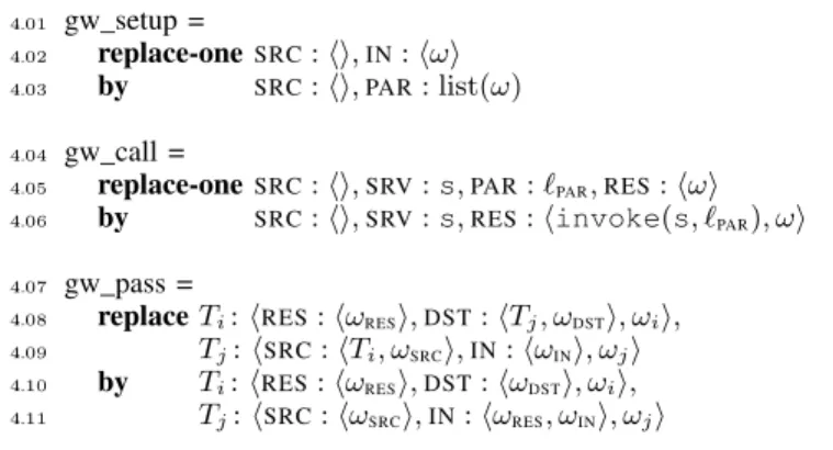
in Fig. 3 is given as input to an HOCL interpreter, it will not trigger anything—it does not comprise rules. Thus, we need to design a set of rules able to, when combined with a workflow description, execute the specified workflow. We now devise a set of three simple rules which constitutes the minimal set of rules allowing any workflow to run. We call these rules generic and prefix their name with gw. They are defined in Fig. 4.
The first two rules prepare and call the service implement-ing a task. They will act inside the subsolution of a service. The third one acts at the workflow level (and will consequently appear at the outermost multiset). It moves data between services as specified by the dependencies. Rule gw_setup detects that all the dependencies of a task have been satisfied by checking that the SRC: hi atom is empty (meaning that it does not have to wait for another element to start) and fills the parameter list in the PAR atom.4 This activates the gw_call
rule which calls the service (with the list of parameters in the
PAR atom), collects the result, and puts it back in the task’s subsolution (in the RES) atom. Rule gw_pass is responsible for transferring results from one source to one destination. Its scope spans two services (one source and one destination). It is triggered after the result has been obtained and placed in the RES atom of the source. It moves the resulting value from the source to each declared destination, through its repeated application. It updates SRC : hi and DST : hi each time it is applied, to remove a satisfied dependency.
Adding these rules (gw_setup and gw_call within each subsolution, and gw_pass inside the global solution) to the abstract workflow described in Fig. 3 makes it a fully func-tional workflow execution program, to be interpreted by an HOCL interpreter. The DAG is the only requirement from the user because the generic rules are inserted automatically prior to execution.
The HOCL workflow description is internal to GinFlow
4Before the execution theINatom can contain data. This input, combined
with the data received from other tasks will constitute the list of parameters of the service (stored in thePARatom). The list() function creates a list.
T1
T2
T3
T4
T2'
Fig. 5: A simple adaptive workflow.
and it is not required directly from the user, who can provide a more user-friendly description of the workflow, for instance using a JSON format (detailed in Section IV). This JSON definition will be then translated internally so as to obtain the required HOCL representation.
C. Adaptive workflow
In this section, we present a programmatic way to change the shape of the workflow on-the-fly. We devise a set of rules, to be included in the HOCL program at run time that will enact this reconfiguration upon the raise of an exception without the need for human intervention during enactment.
Let us consider the workflow depicted in Fig. 5. This is a simple example where Task T2 is considered as potentially
faulty at run time. If T2 actually fails, it is to be replaced
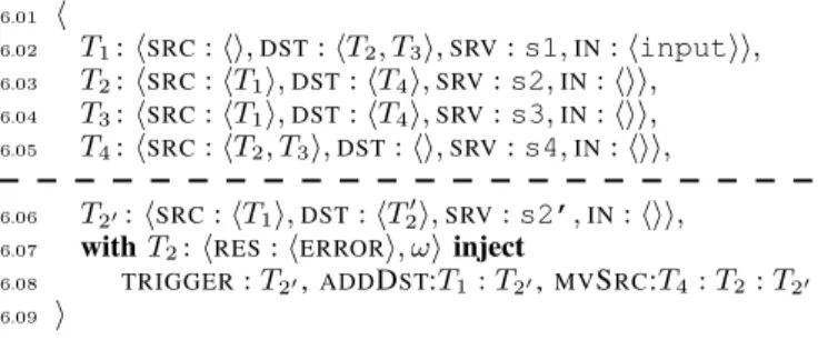
by T20. The corresponding HOCLf low program is given in
Fig. 6. The workflow provided is now organised in two parts. The first part, above the dashed line, is the original workflow (without adaptiveness). The second part, below the dashed line, specifies an alternative behaviour. Line 6.06 defines an alternative task named T20, which is triggered in case T2fails.
The two last lines express the actual adaptation: if the result of T2 is ERROR, then three actions need to be performed:
T20 is injected (to replace T2, and links must be redirected
accordingly). Specifically, T1 needs to resend its result to the
new destination T20 and T4 will not receive its input from T2
but from T20.ADDDSTandMVSRCatoms are simple ways to express these two specific reconfiguration needs, respectively. This code example has been simplified for the sake of clarity. This abstract adaptive workflow, can again be easily derived from the information given by the user, but still
6.01 h 6.02 T1: hSRC: hi,DST: hT2, T3i,SRV: s1,IN: hinputii, 6.03 T2: hSRC: hT1i,DST: hT4i,SRV: s2,IN: hii, 6.04 T3: hSRC: hT1i,DST: hT4i,SRV: s3,IN: hii, 6.05 T4: hSRC: hT2, T3i,DST: hi,SRV: s4,IN: hii, 6.06 T20: hSRC: hT1i,DST: hT20i,SRV: s2’,IN: hii,
6.07 with T2: hRES: hERRORi, ωi inject
6.08 TRIGGER: T20,ADDDST:T1: T20,MVSRC:T4: T2 : T20 6.09 i
Fig. 6: HOCL definition of an adaptive workflow.
7.01 add_dst1 =
7.02 replace-oneDST: hi,ADAPT
7.03 by DST: hT20i
7.04 mv_src4 =
7.05 replace-oneSRC: hωSRCi,IN: hωINi,ADAPT
7.06 by SRC: hωSRC, T20i,IN: hi
7.07 trigger_adapt =
7.08 replace-one T2: hRES: hERRORi, ω2i, T1: hω1i, T4 : hω4i
7.09 by T2: hω2i, T1: hADAPT, ω1i, T4 : hADAPT, ω4i
Fig. 7: Adaptation rules.
needs to get extended to run as intended. The set of rules needed is illustrated in Fig. 7. Firstly, we need rules to adapt destinations and sources. These rules can be derived from the initial ADDDST and MVSRC atoms provided by the user. These rules, namely add_dst1 and mv_src1, are made
explicit in Lines 7.01-7.06. The first one adds T20 as a new
destination to which T1 needs to send its results. The second
one replaces the source from which T4 expects to receive its
input (T2 failed to send its result to T4, and is thus replaced
by T20). Also, it empties the IN tuple atom, which might
contain results that will not be relevant after reconfiguration. Note that the presence of ADAPT is mandatory to apply these adaptation rules. This will make these rules disabled as long as ADAPT is not included. The ADAPT atom is injected into these subsolutions when a failure is detected on T2 (which
is materialised by the trigger_adapt rule). Now we have all the elements to have a concrete adaptive workflow. The full definition for this adaptive workflow is provided in Fig. 8.
Execution: Let us review the execution of the workflow specified in Fig. 8, which illustrates the initial state of the multiset, when the program starts. In this state, the only enabled rule is gw_setup in T1. After it is applied, the gw_call
rule can be applied as gw_setup initialised the PAR atom, required to apply gw_call. A first result is thus created, making gw_pass enabled, matching T1 as the source, and T2 and T3
as destinations. Note that gw_pass is applied twice, filling the
8.01 h
8.02 gw_pass,
8.03 T1: hSRC: hi,DST: hT2, T3i,SRV: s1,IN: hinputi,
gw_setup, gw_call, add_dst1i,
8.04 T2: hSRC: hT1i,DST: hT4i,SRV: s2,IN: hi,
gw_setup, gw_call, trigger_adapti,
8.05 T3: hSRC: hT1i,DST: hT4i,SRV: s3,IN: hi, gw_setup, gw_calli, 8.06 T4: hSRC: hT2, T3i,DST: hi,SRV: s4,IN: hi, gw_setup, gw_call, mv_src4i, 8.07 T20: hSRC: hT1i,DST: hT20i,SRV: s2’,IN: hii 8.08 i
IN atom in T2 and T3. The process can restart in parallel for
T2 and T3. For the sake of illustration, imagine T2invocation
of s2 fails, in which case anERROR atom appears in T2. This
triggers trigger_adapt, making the ADAPT atom appear in
T1 and T4. The presence of this particular atom makes the
add_dst1 and mv_src4 enabled, which adds a destination in
T1and updates the sources in T4so as to switch to the alternate
scenario (include T20). Given this new configuration, gw_pass
is re-enabled and sends T1’s result to T20 which can invoke
s2’. During this time, T3 sent its results to T4. When the
result of T20 also enters T4 subsolution (using gw_pass), the
workflow finishes by triggering gw_call on s4.
Generalisation: The previous examples dealt only with one task being replaced by another one. GinFlow supports more complex adaptations. Any connected part of the workflow can be replaced by another workflow given the following requirement: there must be only one destination for all final services of both (initial and replacement) workflows and it must be the same. The reason behind this restriction is that, if the faulty workflow already produced the output for one of its outgoing links when it fails, this prior-to-failure result will propagate through the rest of the workflow in spite of the computation being replayed through the alternate workflows, possibly leading to conflicting set of data later in the workflow. While this problem could be solved by stopping the workflow, cleaning the execution environment, redesigning the workflow, and restarting it, this falls out of the scope of the paper, which focus on what can be done online.
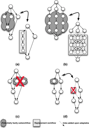
Note that GinFlow can support several adaptations for the same workflow if they concern disjoint sets of tasks. Fig. 9 illustrates these cases: (a) and (b) show valid cases of adapta-tions. In both cases, the programmer defines an alternative sub-workflows satisfying the replacement hypothesis (one common single destination).(c) shows an invalid sub-workflow in the sense that it has multiple outgoing links (leading to potentially inconsistencies in case of adaptation), (d) shows an incorrect reconfiguration: the replacement task communicates with one more service than the service it replaces. As this may have have already been triggered, it could lead again to inconsistencies if it is invoked again. In terms of rules, to propagate the error and trigger the adaptation where required, trigger_adapt rules must be added to any task in the potentially faulty sub-workflow the programmer considers as requiring adaptation if it fails. To allow the sources of the sub-workflow to resend their result, add_dst rules should be added to all the sources of the sub-workflow. To modify the expected sources of result on the destinations of the sub-workflow, a mv_src rule should be added to the destination of the sub-workflow. Each adaptation requires a specific set of the three rules according to the case.
IV. IMPLEMENTATION
This section presents the GinFlow workflow middleware. It is the result of a significant refactoring and extension of the prototype presented in [10]. It sits on the HOCL-core language and interpreter which consists in 18 000 lines of Java code. The middleware itself represents approximately 2 000 more lines of Java code. Fig. 10 depicts the general GinFlow architecture. GinFlow’s distributed core is presented in Section IV-A. Gin-Flow’s resilience mechanisms are discussed in Section IV-B.
X
X
(a) (b)
(c) (d)
Potentially faulty subworkflow Replacement workflow links added upon adaptation
Fig. 9: Valid and invalid cases of adaptations.
Sections IV-C and IV-D focus on the upper layers, namely the executors and the API.
A. The HOCL distributed engine
At the core (the lower layer in Fig. 10), the GinFow middleware consists in a distributed engine. This engine is composed of service agents (SAs) communicating through a shared space (specifically a multiset) containing the description
Local
Command Line Interface
GINFLOW API (JAVA)
JSON Code EXECUTOR Centralized Distributed SSH MESOS EC2* result result HOCL workflow HOCL interpreter S Local multiset start result MQ
of the current status of the workflow. A SA is composed of three elements. The first element is the service to invoke, any wrapper of an application representing this service, or any interface to the service enabling its invocation. The second element is a storage place for a local copy of the multiset. The local copy acts as a cache of the service’s subsolution. The third element is an HOCL interpreter that reads and updates the local copy of the multiset each time it tries to apply one of the rule in the subsolution. In other words, a SA locally stores only its own status. The cache is only read and written locally by this single interpreter, and often pushed back (written) to the multiset. This ensures that coherency problems cannot arise.
Once each SA collect data from the multiset, it communi-cates directly with other agents in a point-to-point fashion, for instance when transmitting data between two workflow tasks. Remind that, as earlier described in Fig. 4, enactment rules have to be generated and injected into the workflow description prior to its execution, (i.e., before any agent starts collecting its initial information from the multiset).
More precisely, the rules presented in Section III-B do not enable a decentralised execution by themselves. In particular, the gw_pass rule is supposed to act from outside subsolutions since it requires to match the atoms from several subsolutions. In the GinFlow environment, this was modified to act from within a subsolution: once the result of the invocation of the service it manages is collected, a SA triggers a local version of the gw_pass rule which calls a function that sends a message directly to the destination SA. It also sends a message to the multiset so as to update the status of the workflow. When the message is received in the multiset, it is simply pushed to the right subsolution. In distributed settings, the trigger_adapt works similarly. The interpreter detecting the failure of its service sends a message to the nodes containing the service to be adapted, by sending them the message containing ADAPT. In GinFlow, the inter-agents communications rely on a message queue middleware which can be either Apache Ac-tiveMQ or Kafka. The choice for one or the other depends on the level of resilience needed by the user, as we detail below. B. Resilience
In this section, we present a mechanism that automates the recovery of failed server agents. This mechanism is orthogonal to the dynamic reconfiguration of the workflow, presented before, and runs in conjunction with it. It takes place at the SA level: when one SA fails, for instance following a hardware crash, another SA will be automatically started to replace it. The difficulty here stands in the ability to replay the work done by the faulty SA prior to its failure.
The state of a SA is reflected by the state of its local solution. Changes in the local solution can result from two mutually exclusive actions : (a) reception of new molecules and (b) reduction of the local solution. Note that a reduction phase is systematically triggered when new molecules are received. This reduction modifies the state of the local solution only if some rule were actually applied during reduction. The SA lifecyle is thus a sequence of receptions and reductions. Consequently, being able to log all incoming molecules of a SA and replay them in the same order on a newly created SA will lead the second SA in the same state as the first.
This soft-stateness nature of the SAs let us envisage a mechanism of fault-recovery which will rebuild the state of a faulty SA. It is assumed that the services invoked are idempotent, or at least free from non-desirable side effects since they can be called several times in case of fault recovery. Thus some duplicated results might be received by some successors of a recovered SA (in case the first SA failed after invoking the service but before finishing the transmission of its results to all its successors). However, the one-shot nature of the rules gw_setup and gw_call ensures that the successors will take into account only the first result received and thus prevent a cascade of useless re-executions.
In the current implementation we exploit the ability of Kafka to persist the messages exchanged by the services and to replay them on demand to facilitate the implementation of this mechanism. The section V-D will present an evaluation of the fault-recovery mechanism.
C. The executors
The role of the executor is to enact the workflow in a specific environment which can be centralised or distributed. The centralised executor will use a single HOCL interpreter to execute the workflow. A distributed executor will (1) claim resources from an infrastructure and (2) provision the dis-tributed engine (i.e., the SAs) on them. In the current version of GinFlow two executors are implemented: SSH-based and Mesos-based. Users have to decide which executor fits the best to their environment. The SSH-based executor starts the SAs on a predefined set of machines, to be specified in the GinFlow configuration file. The Mesos-based executor delegates the deployment of the SAs to the Mesos scheduler [6]. Besides these executors, the abstract nature of the code allows other executors to be implemented (e.g., an EC2 executor to run GinFlow’s distributed engine on EC2-compatible cloud). D. The client interface
Clients can interact in different ways with the GinFlow framework. Firstly, they can use the command line interface, which gives control over various execution options (executor, messaging framework, credentials, etc.). In this case the work-flow is given in a JSON format which will be translated into an HOCL workflow prior to execution. The transformation is done through a Java API. This API is also accessible from another Java program and can be used directly to build the workflow programmatically. Since users only deal with generic workflows (Fig. 2), the phase of rules injection discussed in Section III-C takes place in a transparent way before the actual execution of the workflow starts.
V. EXPERIMENTAL RESULTS
In this section, we present the results of the experimental evaluation of GinFlow. The results exhibited in the following are presented and concerns four dimensions. Firstly, Sec-tion V-A presents a set of performance tests conducted to mea-sure the overhead of the system when increasing the number of services. Secondly, the adaptiveness mechanism is tested in similar settings, and results are presented in Section V-B. Thirdly, in Section V-C, another experiment has been set to evaluate the different configurations of GinFlow, and the
h v
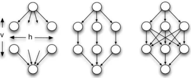
Fig. 11: Diamond workflow, simple and fully connected.
impact of choosing different combinations of executors and messaging middleware. Finally, the SA recovery mechanism detailed in Section IV-B is evaluated in Section V-D using the Mesos/Kafka combination to execute large workflows built with the Montage toolbox. Note that we considered only dis-tributed environments, as it constitutes the natural playground of GinFlow. Thus, the centralised execution of the workflows have not been evaluated.
Experimental setup: All the experiments ran using up
to 25 nodes of the Grid’5000 testbed. Nodes are connected through 1Gbps Ethernet. Debian/Linux Wheezy is installed on the nodes and we used ActiveMQ 5.6.0 and Kafka 0.8.1.1 as the communication middleware. Mesos 0.20 was also installed on the nodes. A total of 568 cores and 1.5 TB RAM were available. The number of SAs per core was limited to two, which allowed to deploy up to 1 000 services. Section V-A and section V-B use ActiveMQ as communication layer.
Case study: Possible shapes of workflows are virtually infinite, however four major patterns, namely split, merge,
sequence and parallel have been recognised to cover the
basic needs of many scientific computational pipelines [13]. We consequently decided to conduct the experiments of Sec-tions V-A, V-B and V-C using a diamond shape depicted in Fig. 11, with h number of services in parallel (for horizontal), and v number of services in a sequence (for vertical). This workflow shape covers all mentioned patterns. This configura-tion comes in two flavours: simple-connected tasks and fully-connectedones. The former is used as base reference and the latter to stress test the executor engine in terms of messages exchanged across the distributed environment. Since we are mainly interested in the coordination time, the tasks (up to 1 000) themselves only simulate a simple script with a (very low) constant execution time. Section V-D uses a workflow whose shape is depicted in Fig. 15. The services are taken from the the well-known Montage toolbox that build mosaic images out of hundreds of astronomical images. This workflow comprises a total of 118 tasks. The output of the workflow is a 3-degree centered image of the M45 star cluster (the pleiades) composed of 100 million pixels.
A. Performance
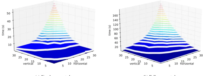
Fig. 12 shows the timespan for both diamond configura-tions. We observe a sustained time increase when the number of services grows. In a simple-connected configuration, the coordination time of the whole workflow execution is close to 54 seconds for 31 × 31 services. This time includes the exchange information between linked services and the update
of the shared multiset. These results are expected because the number of tasks has a direct influence on the time needed for the reduction of sub-solutions: in an HOCL engine, the complexity of the pattern matching process depends on the size of the solution. However, the load of evaluating molecules in the global solution is distributed among all co-engines preventing a combinatorial explosion. The same behaviour is observed confirmed with the fully connected configuration. In this case, we observe the higher cost of coordination and the impact of connections between services. Since a service has to wait for all services of the previous layer, an implicit coordination barrier is set in each service growing the final execution timespan (up to 178 seconds for 31 × 31 services). We can also identify this effect on the projection of the vertical services on the time-vertical plane which shows a higher slope than the time-horizontal one. While a chemical engine has a potential perfomance bottleneck for a large set of services, increasing the number of co-engines limits the final coordination time due to the parallelism, ensuring the scalability of GinFlow in distributed settings.
B. Adaptiveness
In order to evaluate the adaptiveness feature presented in Section III-C, we executed both diamond-shaped workflow flavours in adaptive scenarios. Initially, we performed a regular execution (without adaptiveness) as a reference using square configurations (i.e., with h = v). Then, we executed the same workflows, but raising an execution exception on the last service of the mesh, and replacing the whole body of the diamond on-the-fly. The goal is to observe the effect of adaptiveness after the execution of most of the workflow, and compare it to a complete re-execution of the workflow. These executions are performed in three different scenarios: (1) replacing a simple-connected diamond body by another equivalent, (2) replacing a simple-connected body by another which is fully connected, in a similar way to the schema shown in Fig. 9(b), and (3) replacing a fully connected workflow by another one which is simple-connected. These scenarios were designed to evaluate the cost of adaptiveness when multiple links need to be reconfigured in the outermost (first and last) services of the diamond workflow, to support the replacement of the whole body of the diamond. Fig. 13 exhibits the ratio between the execution with adaptiveness and its counterpart without it, for the three scenarios. In the first scenario, the ratio never exceeds 2. In other words, adaptiveness, in the worst case where every service (except the final one) needs to be replayed, is more performant than a complete re-execution whose time is at least twice the execution of the workflow without adaptiveness. The second scenario shows that for configurations bigger than 1 × 1 the adaptiveness ratio remains in the same order, between 2 and 3, in spite of the significant number of links to reconfigure and the involved services (up to 21 × 21). Finally, the third scenario shows that the ratio remains constant or even decreases when the reconfiguration of the links is simplified during the process of adaptiveness. C. Executor and messaging middleware impact
Fig. 14 depicts the average time (on ten runs) to execute of a 10 × 10 diamond workflow in each executor/communication middleware combination for different numbers of nodes. It is
horizontal 5 10 15 20 25 30 vertical20 15 10 5 25 30 time (s) 10 20 30 40 50
(a) Simple connected
horizontal 5 10 15 20 25 30 vertical20 15 10 5 25 30 time (s) 20 40 60 80 100 120 140 160 (b) Fully connected Fig. 12: Coordination timespan of diamond-shaped workflows.
split in (a) the deployment time (the time taken by the executor to deploy the SAs) and (b) the execution time. Note firstly that the deployment time depends on the scheduling strategy used. The SSH-based executor starts SAs in a round-robin fashion on a preconfigured list of nodes. As the SSH connections are parallelized, the deployment time slighly increases with the number of nodes. GinFlow, on top of Mesos, starts one SA per machine for each offer received from the Mesos scheduler. Thus, increasing the number of nodes will increase the number of machines in each offer and consequently the parallelization in starting the SAs. This explains the linear decrease of the deployment time observed for the Mesos-based executor. Secondly, ActiveMQ outperforms Kafka, as the execution time is approximately 4 times higher in the latter case. Nevertheless, the choice of deploying GinFlow with Kafka is justified by the resilience it helps to provide, as it is experimented in the next section. 1x1 6x6 11x11 16x16 21x21 configuration 0.0 0.5 1.0 1.5 2.0 2.5 3.0 ratio Simple to simple Simple to full Full to simple
Fig. 13: With-adaptiveness-over-without-adaptiveness ratio.
D. Resilience
We now evaluate the resilience mechanisms exposed in Section IV-B. The experiment is based on a realistic workflow (namely, the Montage workflow) and makes use of the Mesos-based executor and Kafka as the communication middleware. The shape of the workflow and tasks’ duration cumulative distribution function (CDF) are depicted in Fig. 15. Note that the services taken from the Montage toolbox are idempotent, in the sense that they can restart safely in regards to a previous failed execution of the same service in the same workflow. The methodology for injecting failures was the following: each running agent failed with a predefined probability p after a certain period of time T . Note that a restarted agent can fail again. Thus, in this model we can expect 1−pp × NT failures
where NT is the number of services whose duration is greater
than T . For each chosen values of p and T , we repeated the execution of the workflow up to 10 times. All the following
5 10 15 5 10 15 5 10 15 5 10 15 Nodes 0 20 40 60 80 100 Time (s) SSH/ActiveMQ SSH/Kafka Mesos/ActiveMQ Mesos/Kafka
10x10 Diamond Simple Connected Execution
Deployment
…108… T< 20 20<T<60 60<T 0 50 100 150 200 250 300 350 Time (s) 0.0 0.2 0.4 0.6 0.8 1.0 1.2 Services (%)
Fig. 15: Shape and CDF for the Montage workflow.
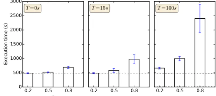
mentioned values are obtained by averaging the values on these runs. The bar plots of Fig. 16 show the execution time with various values for p and T . The dashed line on each subplot corresponds to an execution without any failure. In this case the execution time is 484s in average and the standard deviation is 13.5 seconds.
Firstly, when T = 0, increasing p allows to appreciate the recovery velocity. We observed 26, 114 and 487 failures in average for p = 0.2, p = 0.5 and p = 0.8 respectively. Fig. 16 shows an increase of 3s, 36s and 208s respectively in the average execution time of the workflow, showing that the recovery velocity slightly decrease when increasing the failures rate. In other words, the ratio between the overhead and the number of failures slightly increases. Secondly, choosing T = 15s shows that services can recover even if they fail after some processing. Moreover, note that, according to the CDF, 95% of the services have a running time which is greater than 15s and thus, they may be affected by failures. In our specific workflow, we found that some services may fail silently. More precisely, the durations of the services in the large parallel part of the workflow are quite heterogeneous: from 60s to 310s. Some services in this section can recover without impacting the global execution time. For example, a 60s service can fail five times without exceeding the execution time of a 200s service that do not fail. On the contrary the execution time of the workflow is more sensitive to the failures of some specific services (e.g., the merge sevices). These two considerations can explain the increase of the standard deviation observed in Fig. 16. Finally choosing T = 100s will impact exclusively services in the large parallel part of the workflow. For each value of p we observed that the maximum number of failures for a service was respectively 3, 6 and 21 (averaged on 10 runs), leading to a maximum increase of 300s, 600s and 2100s of the average execution time of the workflow. This values are consistent with Fig. 16.
This experiment, based on a specific but well-known work-flow shows that GinFlow is robust enough to enact workwork-flows even on a very unstable infrastructure dealing with long task executions and large workflows.
VI. RELATED WORKS
Decentralising the coordination of the workflow execution was first pursued relying on direct interactions (based on messaging) between services. In [14], the authors introduce service invocation triggers, a lightweight infrastructure that
0.2 0.5 0.8 p 0 500 1000 1500 2000 2500 3000 Execution time (s) T=0s 0.2 0.5 0.8 T=15s 0.2 0.5 0.8 T=100s
Fig. 16: Execution time with different failure scenarios.
routes messages directly from a producer service to a consumer one, where each service invocation trigger corresponds to the invocation of a service. In [15], a distributed execution engine is proposed based on a peer-to-peer architecture wherein nodes (similar to local engines) are distributed across multiple computer systems, and communicate by direct point-to-point notifications. A continuation-passing style, where information on the remainder of the execution is carried in messages, has been proposed in [16]. Nodes interpret such messages and thus conduct the execution of services without consulting a cen-tralised engine. However, nodes need to know explicitly which nodes to interact with and when, in a synchronous manner. A distributed workflow system based on mobile libraries playing the role of engines was presented in [17]. However, the details of the coordination are not described.
To increase loose coupling between services, a series of works relying on a shared space to exchange information between nodes have been proposed [4], [18], [19]. Following the Linda programming model [8], a tuplespace works as a piece of memory shared by all interacting parties. Thus, using tuplespace for coordination, the execution of a part of a workflow within each node is triggered when tuples, matching the templates registered by the respective nodes, are present in the tuplespace. In the same vein, works such as KLAIM [9], propose a distributed architecture based on Linda where distributed tuplespaces store data and programs as tuples, allowing mobile computations by transferring pro-grams from one tuple to another. However, in these works, the tuplespace is only used to store data information. The chemical programming model enhances the tuplespace model by providing a support for dynamics, and allows us to store both control and data information in the multiset.
The idea of using chemical programming to enact work-flows autonomously is not new [20], [21]. These works, however, remain very abstract, and only few clues are given in these works on how to implement such approach. The recent series of work [5], [10], [22] paved the way in terms of programming model and software prototyping for the present work. The contributions of the present paper over them are (1) a programmatic way to enable on-the-fly workflow updates, (2) the implementation and experimentation of this adaptation in decentralised settings.
Most of workflow manager systems initiatives achieve the required enactment flexibility by means of the infrastructure (e.g., re-submissions strategies [23], pilot jobs [24], task
replications [25]). On the other hand, Tolosana-Calasanz et al. [26] propose an adaptive exception handling for scientific workflows at definition level. Their work proposes two patterns to manage the exception handling based on the Reference Nets-within-Nets formalism: propagation and replacement. In spite of mechanisms for dynamically adapting the workflow struc-ture at run time without having to be aware of the underlying infrastructure, the resulting representation with their reference model suggests a quite complex workflow definition, where the original scenario and the alternative path are mixed.
VII. CONCLUSION
Shared space-based coordination for workflow execution has shown to provide appropriate building blocks for the decentralised execution of workflows. In this paper, we have devised a programmatic way to specify adaptive workflows in decentralised environments. We have shown how, based on the chemical programming model, it is possible to modify the workflow description on-the-fly without needing to stop and restart the workflow from the beginning. We have imple-mented these concepts in the GinFlow middleware. GinFlow was evaluated using synthetic and real workflows extensively in distributed environments. The obtained results show its scalability and resilience even in extremely unreliable settings. GinFlow is currently being integrated inside the Tigres workflow execution environment, developed at Lawrence Berkeley National Laboratory [27].
REFERENCES
[1] K. Wolstencroft, R. Haines, D. Fellows, A. Williams, D. Withers, S. Owen, S. Soiland-Reyes, I. Dunlop, A. Nenadic, P. Fisher, J. Bhagat, K. Belhajjame, F. Bacall, A. Hardisty, A. N. de la Hidalga, M. P. B. Vargas, S. Sufi, and C. Goble, “The Taverna Workflow Suite: Designing and Executing Workflows of Web Services on the Desktop, Web or in the Cloud,” Nucleic Acids Res., vol. 41, no. W1, pp. W557–W561, 2013.
[2] B. Ludäscher, I. Altintas, C. Berkley, D. Higgins, E. Jaeger, M. Jones, E. A. Lee, J. Tao, and Y. Zhao, “Scientific workflow management and the Kepler system,” Concurrency Comput.: Pract. Exper., vol. 18, no. 10, pp. 1039–1065, 2006.
[3] T. Glatard, J. Montagnat, D. Lingrand, and X. Pennec, “Flexible and efficient workflow deployment of data-intensive applications on grids with MOTEUR,” Int. J. High Perform. Comput. Appl., vol. 22, no. 3, pp. 347–360, 2008.
[4] M. Sonntag, K. Gorlach, D. Karastoyanova, F. Leymann, and M. Reiter, “Process Space-based Scientific Workflow Enactment,” International Journal of Business Process Integration and Management, vol. 5, no. 1, pp. 32–44, 2010.
[5] H. Fernández, T. Priol, and C. Tedeschi, “Decentralized approach for execution of composite Web services using the chemical paradigm,” in Proceedings of the 8th IEEE International Conference on Web Services, Miami, FL, Jul. 2010.
[6] B. Hindman, A. Konwinski, M. Zaharia, A. Ghodsi, A. D. Joseph, R. Katz, S. Shenker, and I. Stoica, “Mesos: A platform for fine-grained resource sharing in the data center,” in Proceedings of the 8th USENIX Conference on Networked Systems Design and Implementation, Boston, MA, Apr. 2011.
[7] R. Bolze, F. Cappello, E. Caron, M. J. Daydé, F. Desprez, E. Jeannot, Y. Jégou, S. Lanteri, J. Leduc, N. Melab, G. Mornet, R. Namyst, P. Primet, B. Quétier, O. Richard, E. Talbi, and I. Touche, “Grid’5000: A large scale and highly reconfigurable experimental grid testbed,” Int. J. High Perform. Comput. Appl., vol. 20, no. 4, pp. 481–494, 2006. [8] D. Gelernter, “Generative communication in Linda,” ACM Trans.
Pro-gram. Lang. Syst., vol. 7, no. 1, pp. 80–112, 1985.
[9] R. D. Nicola, G. Ferrari, and R. Pugliese, “KLAIM: A kernel language for agents interaction and mobility,” IEEE Trans. Softw. Eng., vol. 24, no. 5, pp. 315–330, 1998.
[10] H. Fernández, C. Tedeschi, and T. Priol, “Rule-driven service co-ordination middleware for scientific applications,” Future Generation Computer Systems, vol. 35, pp. 1–13, 2014.
[11] N. Cerezo, J. Montagnat, and M. Blay-Fornarino, “Computer-assisted scientific workflow design,” Journal of Grid Computing, vol. 11, no. 3, pp. 585–612, 2013.
[12] J.-P. Banâtre, P. Fradet, and Y. Radenac, “Generalised multisets for chemical programming,” Mathematical Structures in Computer Science, vol. 16, no. 4, pp. 557–580, 2006.
[13] L. Ramakrishnan, S. Poon, V. Hendrix, D. Gunter, G. Z. Pastorello, and D. Agarwal, “Experiences with user-centered design for the Tigres workflow API,” in Proceedings of the 10th IEEE International Confer-ence on e-SciConfer-ence, Guarujá, Brazil, Oct. 2014.
[14] W. Binder, I. Constantinescu, and B. Faltings, “Decentralized or-chestration of composite Web services,” in Proceedings of the IEEE International Conference on Web Services, Chicago, IL, Sep. 2006. [15] R. A. Micillo, S. Venticinque, N. Mazzocca, and R. Aversa, “An
agent-based approach for distributed execution of composite Web services,” in Proceedings of the 17th IEEE International Workshops on Enabling Technologies, Roma, Italia, Jun. 2008.
[16] W. Yu, “Consistent and decentralized orchestration of BPEL processes,” in Proceedings of the ACM symposium on Applied Computing, Hon-olulu, HI, Mar. 2009.
[17] P. Downes, O. Curran, J. Cunniffe, and A. Shearer, “Distributed radiotherapy simulation with the webcom workflow system,” Int. J. High Perform. Comput. Appl., vol. 24, pp. 213–227, 2010.
[18] P. A. Buhler and J. M. Vidal, “Enacting BPEL4WS specified workflows with multiagent systems,” in In Proceedings of the Workshop on Web Services and Agent-Based Engineering, Jul. 2004.
[19] D. Martin, D. Wutke, and F. Leymann, “A novel approach to decen-tralized workflow enactment,” in Proceedings of the 12th International IEEE Enterprise Distributed Object Computing Conference, Munich, Germany, Sep. 2008.
[20] Z. Németh, C. Pérez, and T. Priol, “Workflow enactment based on a chemical methaphor,” in Proceedings of the 3rd IEEE International Conference on Software Engineering and Formal Methods, Koblenz, Germany, Sep. 2005.
[21] C. Di Napoli, M. Giordano, Z. Németh, and N. Tonellotto, “Adaptive instantiation of service workflows using a chemical approach,” in Proceedings of the 16th International Euro-Par Conference on Parallel Processing, Ischia, Italy, Aug. 2010.
[22] H. Fernández, C. Tedeschi, and T. Priol, “A chemistry-inspired work-flow management system for scientific applications in clouds,” in Proceedings of the 7th IEEE International Conference on e-Science, Stockholm, Sweden, Dec. 2011.
[23] D. Lingrand, J. Montagnat, and T. Glatard, “Modeling user submission strategies on production grids,” in Proceedings of the 18th ACM International Symposium on High Performance Distributed Computing, Munich, Germany, Jun. 2009.
[24] A. Casajus, R. Graciani, S. Paterson, and A. Tsaregorodtsev, “DIRAC pilot framework and the DIRAC workload management system,” Jour-nal of Physics: Conference Series, vol. 219, no. 6, 2010.
[25] R. Ferreira da Silva, T. Glatard, and F. Desprez, “Self-healing of workflow activity incidents on distributed computing infrastructures,” Future Generation Computer Systems, vol. 29, no. 8, pp. 2284–2294, 2013.
[26] R. Tolosana-Calasanz, J. A. Bañares, O. F. Rana, P. Álvarez, J. Ezpeleta, and A. Hoheisel, “Adaptive exception handling for scientific work-flows,” Concurrency Comput.: Pract. Exper., vol. 22, no. 5, pp. 617– 642, 2010.
[27] J. Rojas Balderrama, M. Simonin, C. Morin, V. Hendrix, L. Ramakr-ishnan, D. Agarwal, and C. Tedeschi, “Combining workflow templates with a shared space-based execution model,” in Proceedings of the 9th Workshop on Workflows in Support of Large-Scale Science, New Orleans, LA, Nov. 2014.