To link to this article: DOI: 10.1149/2.039112jes
URL : http://dx.doi.org/10.1149/2.039112jes
This is an author-deposited version published in:
http://oatao.univ-toulouse.fr/
Eprints ID: 5783
To cite this version:
Musiani, M. and Orazem, Mark E. and Pébère, Nadine and Tribollet,
Bernard and Vivier , Vincent Constant-Phase-Element Behavior Caused
by Coupled Resistivity and Permittivity Distributions in Films. (2011)
Journal of The Electrochemical Society (JES), vol. 158 (n° 12). pp.
C424-C428. ISSN 0013-4651
O
pen
A
rchive
T
oulouse
A
rchive
O
uverte (
OATAO
)
OATAO is an open access repository that collects the work of Toulouse researchers
and makes it freely available over the web where possible.
Any correspondence concerning this service should be sent to the repository
administrator:
[email protected]
Constant-Phase-Element Behavior Caused by Coupled Resistivity
and Permittivity Distributions in Films
M. Musiani,aM. E. Orazem,b,∗,zN. P´eb`ere,c,∗∗B. Tribollet,d,∗and V. Vivierd,∗∗
aIstituto per l’Energetica e le Interfasi, Consiglio Nazionale delle Ricerche, 35127 Padova, Italy bDepartment of Chemical Engineering, University of Florida, Florida 32611, USA
cUniversit´e de Toulouse, CIRIMAT, UPS / INPT / CNRS, ENSIACET, 31030 Toulouse Cedex 4, France
dLaboratoire Interfaces et Syst`emes Electrochimiques, UPR 15 du CNRS, Universit´e Pierre et Marie Curie, 75252,
Paris Cedex 05, France
A recent proposed model showed that the impedance of a film with a uniform permittivity and a resistivity that varies along its thickness according to a power-law is in the form of a constant phase element (CPE). This model is further considered in order to assess the effect of non-uniform permittivity profiles. It is shown that a power-law permittivity profile is also compatible with a CPE behavior when resistivity and permittivity vary in opposite ways along the film thickness. This work shows that, for important classes of materials which show CPE behavior, relaxation of the assumption of a uniform permittivity does not alter the conclusions developed in the earlier work, and the formula relating film properties to CPE parameters is shown to apply.
[DOI:10.1149/2.039112jes]
In a recent paper, Hirschorn et al.1showed that the impedance of a film, with a uniform permittivity (ε) and a resistivity (ρ) that varies along its thickness (δ) according to a power-law, is in the form of a constant phase element (CPE) in a well-defined frequency range be-tween two characteristic frequencies (defined below). The existence of marked variations in the impedance of organic coatings along their thickness had been experimentally shown some years ago by Kittel et al.2These workers pointed out that it would be desirable “to use a mathematical model integrating a properties gradient over the thick-ness of the coatings,”3but did not propose any specific resistivity or permittivity profiles. In Ref.1the film resistivity was written as:
ρ(ξ) ρ(δ)= · ρ(δ) ρ(0)+ µ 1 −ρ(δ) ρ(0) ¶ ξγ ¸−1 [1] where ρ(0) and ρ(δ) are the boundary values of resistivity at the inter-faces, ξ =x/δ (x is the distance along the film thickness) and γ is a parameter indicating how sharply the resistivity varies. Formulas for the calculation of ρ(0), ρ(δ) and γ from the experimental data were proposed, which however, to be applied, required the knowledge of both δ and ε. In many cases, the film thickness may be measured by microscopic or spectroscopic techniques, and a fairly accurate per-mittivity value may be estimated when the chemical composition of the film is known. In the same paper,1 it was pointed out that, if the resistivity distribution results from an inhomogeneous layer compo-sition, then a permittivity profile may also be expected. Although the variations of ε should be much smaller than those of ρ, they may influence the shape of the impedance diagrams.
The present communication addresses the influence of a non-uniform permittivity on the impedance of a film with a power-law resistivity profile. The discussion is mainly focused on the case of a coating that uptakes an electrolytic solution in an inhomogeneous way, more strongly in its outer part, in contact with the electrolyte, than in its inner part, in contact with the metal, as observed by Kittel et al.3 for epoxy vinyl primer coatings with TiO2and ZnSO4 as additives. Such a situation is compatible with the resistivity profile described by equation1with ρ(0) > ρ(δ), assuming that x = 0 and x = δ denote the metal/coating and coating/electrolyte interfaces, respectively. As the electrolytic solution uptake is expected to cause an increase in the coating permittivity,4–6one should expect a permittivity profile with
ε(0) < ε(δ).
∗ Electrochemical Society Fellow. ∗∗ Electrochemical Society Active Member.
zE-mail:[email protected]
Results and Discussion
For the present analysis, the permittivity was assumed to vary along the film thickness, in a manner similar to that of the resistivity, according to a power-law, i.e.,
ε(ξ) ε(δ)= · ε(δ) ε(0)+ µ 1 −ε(δ) ε(0) ¶ ξγ′¸ −1 [2] In equation2, γ′ is used as power-law exponent to indicate that, in principle, it may not coincide with γ. However, if the cause of the resistivity and permittivity profiles is the same, e.g., a composition profile, it is logical to assume that ρ and ε should vary on the same scale length and therefore γ = γ′. This case is considered, at first, in greater detail; the effect of assuming γ 6= γ′is discussed later.
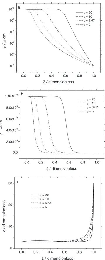
A set of resistivity and permittivity profiles calculated according to equations1and2, respectively, are presented in Figure1for various values of the power-law exponent γ = γ′. The resistivity values at ξ =0 and ξ = 1 are given by ρ(0) = 1010Äcm and ρ(δ) = 105Äcm respectively. The logarithmic scale shown in Figure1aillustrates the power-law nature of the distribution; whereas, the linear presentation of scaled resistivity in Figure1bshows that the resistivity becomes very small with respect to the maximum resistivity, ρ(0), over a sig-nificant portion of the film.
A permittivity ε(0) = 3 was assumed at the metal/coating interface because such a value is within the expected range for dry polymeric materials. A permittivity ε(δ) = 30 was assumed to apply for the coating/electrolyte interface. This value, 10 times larger than ε(0), would correspond to a massive electrolyte uptake4–6 (for example, to ca 50% volume fraction of electrolyte according to Brasher and Kingsbury4 and to at least 28% volume fraction according to other effective medium formulas6). The resulting permittivity, presented in a linear scale in Figure1c, shows that the permittivity increases markedly only in the outer part of the film where the resistivity is very small.
The film impedance, given by Zf(ω) = δ Z 1 0 1 ρ(ξ)−1+ j ωε(ξ)ε 0 dξ [3]
was numerically calculated over a wide frequency range, markedly larger than the one usually employed in experiments. The large fre-quency range is employed here to explore fully the dielectric response of the film. At the highest frequencies reported in the present work, one may expect to observe other high-frequency phenomena, not in-cluded in the model, such as dielectric relaxation of the electrolyte. The frequency dependencies of the real part (a) imaginary part (b), and
0.0 0.2 0.4 0.6 0.8 1.0 105 106 107 108 109 1010 a ρ / Ω cm ξ / dimensionless γ = 20 γ = 10 γ = 6.67 γ = 5 0.0 0.2 0.4 0.6 0.8 1.0 0.0 2.0x10⁹ 4.0x10⁹ 6.0x10⁹ 8.0x10⁹ 1.0x10¹⁰ b ρ / Ω cm ξ / dimensionless γ = 20 γ = 10 γ = 6.67 γ = 5 0.0 0.2 0.4 0.6 0.8 1.0 0 10 20 30 c γ' = 20 γ' = 10 γ' = 6.67 γ' = 5 ε / dimensionless ξ / dimensionless
Figure 1. Resistivity and permittivity profiles calculated according to
equa-tions1and2, respectively, with ρ(0) = 1010Äcm, ρ(δ) = 105Äcm, ε(0) =3, ε(δ) = 30, δ = 2 10−4cm, and γ = γ′as a parameter: a) resistivity on logarithmic scale; b) resistivity on linear scale; and c) permittivity on linear scale.
derivatived log(−Zj)/dlog( f ) (c) are presented in Figure2for the
values of ρ(0), ρ(δ), γ and γ′corresponding to the resistivity and per-mittivity profiles shown in Figure1. These plots clearly show a CPE behavior over the range between 100 Hz and 1 MHz, highlighted by the constantd log(−Zj)/dlog( f ) value which corresponds to the CPE
exponent α,7linked to the power-law exponent γ by the relationship1
α =(γ − 1)/γ [4]
Thus, a non-uniform permittivity profile is compatible with a CPE behavior. However, it is important to note that, in Figure1, the per-mittivity varies sharply only in a ξ range where the resistivity is very small, i.e. in a part of the film that contributes to the overall impedance in an almost negligible way.
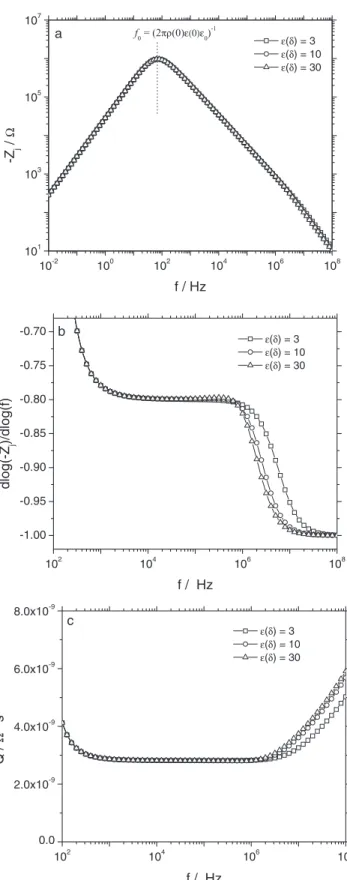
The fact that a CPE behavior is still observed when ε is not uniform does not necessarily mean that the formulas proposed in Ref.1can still be used to calculate ρ(0) and ρ(δ). To clarify this point, the impedance plots shown in Figure3were calculated. A film with a uniform permittivity (ε(0) = ε(δ) = 3) was compared to films with inhomogeneous permittivity; permittivity variations between ε(0) = 3 and ε(δ) = 10 (roughly corresponding to 25% water uptake4at the coating/electrolyte interface) and between ε(0) = 3 and ε(δ) = 30 were considered. The frequency dependence of the imaginary part of the impedance is shown in Figure3a. The real part is not shown, as it does not convey additional information.
Clearly, minor differences are seen only in the very high fre-quency range, where the film behaves as an ideal capacitor.1 Both the frequency range over which CPE behavior is observed and the low-frequency range are unaffected by the permittivity profile. In par-ticular, the characteristic frequency at which the imaginary part goes through a maximumf0, given by
f0=(2πρ(0)ε(0)ε0)−1 [5] does not depend on ε(δ). Thus, the experimental value of f0can still be
used for the calculation of ρ(0), provided the permittivity of the dry coating material is used as ε(0). The values of d log(−Zj)/dlog ( f )
presented in Figure 3b, for the most significant frequency ranges, shows that ε(δ) has almost no influence on the CPE exponent α. The minor differences among the plots would not be significant in experiments. The frequency dependence of the CPE parameterQ, calculated as7 Q = sin³απ 2 ´ −1 Zj(2πf )α [6]
is presented in Figure3c. Clearly, although the range over whichQ is constant is somewhat smaller when ε(δ) is larger, the Q value is unaffected by the permittivity profile. Thus, given that both α andQ are insensitive to the permittivity profile, ρ(δ) can still be calculated as1
ρ(δ) = [ε(0)ε0]α/(1−α)[Qgδ]1/(α−1) [7] using for ε(0) the permittivity of the dry coating material. In equation7,g is a function of α, with a value close to 1, and is given by g =1 + 2.88(α − 1)2.375.1Therefore, if the film resistivity and permit-tivity are given by equations1and2, respectively, the quantities that define the resistivity profile, i.e. γ, ρ(0) and ρ(δ) may be calculated using equations4,5, and7respectively, with the permittivity of the dry coating material given as ε(0).
In Ref.1, ρ(δ) was also expressed as ρ(δ) = (2π fδεε0)−1, wherefδ is the characteristic frequency marking the transition between the CPE and the capacitive behavior. Such a formula cannot be directly used for the calculation of ρ(δ) because fδdepends on ε(δ). In addition, fδis
10-2 100 102 104 106 108 10-4 10-2 100 102 104 106 108 f0 f δ a γ = γ' = 20 γ = γ' = 10 γ = γ' = 6.67 γ = γ' = 5 Z r / Ω f / Hz 10-2 100 102 104 106 108 100 102 104 106 108 γ = γ' = 20 γ = γ' = 10 γ = γ' = 6.67 γ = γ' = 5 fδ f0 b -Z j / Ω f / Hz 10-2 100 102 104 106 108 -1.0 -0.5 0.0 0.5 1.0 γ = γ' = 20 γ = γ' = 10 γ = γ' = 6.67 γ = γ' = 5 c dlog(-Z j )/dlog(f) f / Hz
Figure 2. Impedance plots calculated according to equation3for resistivity
and permittivity profiles given by equations1and2, respectively, with ρ(0) = 1010 Äcm, ρ(δ) = 105 Ä cm, ε(0) = 3, ε(δ) = 30, δ = 2 10−4 cm, and γ = γ′ as a parameter: a) real part of the impedance, (b) imaginary part of the impedance; and c)d log(−Zj)/dlog( f ) corresponding to the CPE
exponent α. 10-2 100 102 104 106 108 101 103 105 107 a f0 = (2πρ(0)ε(0)ε0)-1 ε(δ) = 3 ε(δ) = 10 ε(δ) = 30 -Z j / Ω f / Hz 102 104 106 108 -1.00 -0.95 -0.90 -0.85 -0.80 -0.75 -0.70 b ε(δ) = 3 ε(δ) = 10 ε(δ) = 30 dlog(-Z j )/dlog(f) f / Hz 102 104 106 108 0.0 2.0x10⁻⁹ 4.0x10⁻⁹ 6.0x10⁻⁹ 8.0x10⁻⁹ c ε(δ) = 3 ε(δ) = 10 ε(δ) = 30 Q / Ω -1 s α f / Hz
Figure 3. Impedance plots calculated according to equation3for resistivity
and permittivity profiles given by equations1and2, respectively, with ρ(0) = 1010Äcm, ρ(δ) = 105Äcm, ε(0) = 3, γ = γ′=5, δ = 2 10−4cm, and ε(δ) as a parameter: a) imaginary part of the impedance; b)d log(−Zj)/dlog( f )
102 104 106 108 -1.00 -0.95 -0.90 -0.85 -0.80 -0.75 -0.70 -0.65 Uniform; ε = 3 Power-Law; ε(0) = 3 ε(δ) = 30 Power-Law; ε(0) = 30 ε(δ) = 3 Linear; ε(0) = 3 ε(δ) = 30 dlog(-Z j )/dlog(f) f / Hz
Figure 4. Frequency dependence of the slope d log(−Zj)/dlog ( f )
cor-responding to the CPE exponent α, calculated according to equation 3, for a film with a power-law resistivity profile (ρ(0) = 1010 Ä cm, ρ(δ) = 105 Äcm, γ = γ′ =5, δ = 2 10−4 cm) and for different permittivity profiles as indicated on the figure.
often higher than the upper frequency limit used in the experiments,8,9 and, for such cases, its use for the calculation of ρ(δ) is precluded.
Impedance values were calculated for other permittivity profiles in order to assess which permittivity profiles were compatible with the observation of a CPE behavior, when coupled with a power-law resistivity. In Figure4, values ford log(−Zj)/dlog ( f ) are presented
as a function of frequency for four different cases: (i) uniform per-mittivity; (ii) power-law permittivity profile given by equation2with γ = γ′and ε(0) < ε(δ); (iii) power-law permittivity profile given by equation2with γ = γ′and ε(0) > ε(δ); and (iv) linear permittivity profile, with ε(0) < ε(δ), given by
ε(x) = ε(0) − [ε(0) − ε(δ)]ξ [8]
As already shown above, distributions (i) and (ii) lead to a CPE be-havior, but distributions (iii) and (iv) do not, most probably because, in both cases, the film permittivity changes significantly with ξ in its inner and more resistive part.
Additional simulations were performed with permittivity values following distribution (ii) but with ε(δ) = 300. Such large values
of ε(δ) are consistent with dielectric constant values reported for
some oxides by Shannon.10Even for these more extreme changes in permittivity, the impedance was unaffected by the permittivity distri-bution, and equation7provided an accurate relationship between CPE parameters and film properties. Other simulations were performed which showed that even a staircase distribution of permittivity will show CPE behavior so long as the increase in permittivity takes place in regions where the resistivity is small.
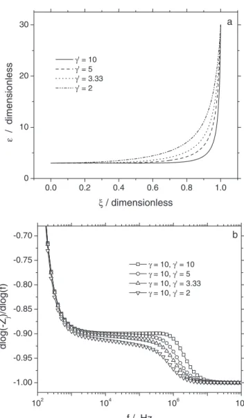
Figure5ashows permittivity profiles calculated for various γ′ val-ues. As γ′becomes smaller, the permittivity profile becomes smoother and the film depth over which a non-negligible ε variation occurs ex-tends to lower ξ values. Figure5bshows the frequency dependence of the sloped log(−Zj)/dlog ( f ), corresponding to the CPE exponent
α, calculated by assuming a constant value of γ = 10, i.e. a fixed ρprofile (dashed curves in Figures1aand1b), and different γ′ val-ues. Clearly, as the difference between γ and γ′becomes larger the
d log(−Zj)/dlog ( f ) vs. frequency plots diverge from a pure CPE
behavior and α becomes frequency dependent. As mentioned above, a significant variation of ε with ξ in the most resistive part of the film appears not to be compatible with a CPE. Of course, the deviation from a CPE behavior would be less evident for differences between
ε(0) and ε(δ) lower than those, quite large, considered in Figure5.
0.0 0.2 0.4 0.6 0.8 1.0 0 10 20 30 a ε / dimensionless ξ / dimensionless γ' = 10 γ' = 5 γ' = 3.33 γ' = 2 102 104 106 108 -1.00 -0.95 -0.90 -0.85 -0.80 -0.75 -0.70 γ = 10, γ' = 10 γ = 10, γ' = 5 γ = 10, γ' = 3.33 γ = 10, γ' = 2 b dlog(-Z j )/dlog(f) f / Hz
Figure 5. Permittivity profiles (a) and d log(−Zj)/dlog ( f ) vs. frequency
plots (b) calculated according to equations2and3respectively, with ρ(0) =1010Äcm, ρ(δ) = 105Äcm, ε(0) = 3, ε(δ) = 30, δ = 2 10−4cm, and the γand γ′values indicated on the figures.
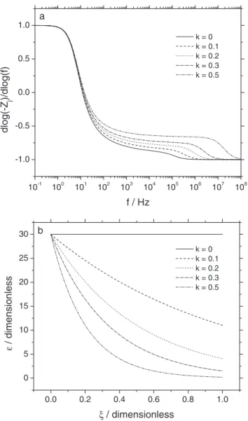
In Ref.1, the power-law resistivity profile was compared to the exponential profile proposed by Young11 and the authors observed that the latter does not yield a CPE behavior, in agreement with G¨ohr et al.12The plots ofd log(−Z
j)/dlog ( f ) as a function of frequency,
shown in Figure6a, were calculated according to equation3, assuming a Young-type resistivity profile with a characteristic length λ, and an exponential permittivity profile, with a characteristic length λ/k, i.e.
ρ(x) = ρ(0) expµ −x λ ¶ [9] and ε(x) = ε(0) expµ −kx λ ¶ [10] wherek is a dimensionless constant relating the two distributions. It may be seen that such a combination of exponential profiles may yield a CPE behavior. In this case, however, both ρ and ε vary withx in the same way, i.e. if ρ(0) > ρ(δ) then ε(0) > ε(δ), and the CPE behavior is better defined for largerk values, i.e. sharper ε profiles, leading to α values quite far from 1, seldom encountered in experimental results. The associated permittivity distributions given in Figure6bshow that largek values are likely to correspond to unrealistically wide variations
10-1 100 101 102 103 104 105 106 107 108 -1.0 -0.5 0.0 0.5 1.0 a dlog(-Z j )/dlog(f) f / Hz k = 0 k = 0.1 k = 0.2 k = 0.3 k = 0.5 0.0 0.2 0.4 0.6 0.8 1.0 0 5 10 15 20 25 30 b k = 0 k = 0.1 k = 0.2 k = 0.3 k = 0.5 ε / dimensionless ξ / dimensionless
Figure 6. Impedance results calculated according to equation3for resistivity
and permittivity profiles given by equations9and10, respectively, with ρ(0) =1010Äcm, ε(0) = 30, δ = 10−6cm, λ = 10−7cm, andk as a parameter: a) d log(−Zj)/dlog ( f ), corresponding to the CPE exponent α, as a function of
frequency; and b) permittivity profiles calculated according to equation10.
of ε across the film. The ε(δ) values are ca. 11 for k = 0.1, 4 for k = 0.2, 1.5 fork = 0.3 and a physically meaningless 0.2 for k = 0.5.
Hirschorn et al.8 reported on the use of equation7, derived un-der the assumption of a uniform permittivity profile, for a variety of systems, including some for which the assumption of a uniform
permittivity was clearly inappropriate. The present work shows that, so long as the permittivity increases according to equation2and the resistivity decreases according to equation1, with γ = γ′, equation7 provides a valid relationship between CPE and film parameters. For systems exhibiting CPE behavior, the distribution in permittivity is overwhelmed by the distribution of resistivity. Thus, changes to the film that influence permittivity in the outer region will not influence the impedance response.
Other distributions, such as the Young model, which employs an exponential variation of resistivity, do not yield CPE behavior. Com-binations of exponential changes in permittivity and resistivity, in which both increase with position in the same way, will give rise to CPE behavior, but the required profiles are physically unreasonable.
In principle, the concepts reported in the present paper for electrolyte-penetrated organic coatings may apply – at least as a first approximation – to other systems like, for example, passive oxide with inhomogeneous properties along their depth (often described as duplex films consisting of an inner compact, resistive layer and an outer hydrated layer), provided the resistivity and permittivity profiles fulfill the requirements described above.
Conclusions
Numerical calculations have been used to assess the influence of a permittivity profile, coupled to a power-law resistivity profile, on the observation of a CPE behavior in films. It has been shown that a power-law permittivity profile is compatible with a CPE behavior when ρ and ε vary with ξ in opposite ways on the same scale length. Such a situation is quite likely to occur in organic coatings which inhomogeneously uptake a conductive water solution. Some other permittivity profiles have been shown to be incompatible with a CPE. A CPE behavior may be observed also for films with exponential profiles of their properties, when ρ and ε vary with ξ in the same way, but the corresponding permittivity variations are likely to be too large to be physically acceptable.
References
1. B. Hirschorn, M. E. Orazem, B. Tribollet, V. Vivier, I. Frateur, and M. Musiani,
J. Electrochem. Soc.,157, C452 (2010).
2. J. Kittel, N. Celati, M. Keddam, and H. Takenouti,Prog. Org. Coat.,41, 93 (2001).
3. J. Kittel, N. Celati, M. Keddam, and H. Takenouti,Prog. Org. Coat.,46, 135 (2003).
4. D. M. Brasher and A. H. Kingsbury,J. Appl. Chem.4, 62 (1954).
5. R. E. Meredith and C. W. Tobias, in Advances in Electrochemistry and Electrochem-ical Engineering, edited by C. W. Tobias, Vol. 2 (Interscience, New York, 1962), p. 15
6. O. A. Stafford, B. R. Hinderliter, and S. G. Croll,Electrochim. Acta,52, 1339
(2006).
7. M. E. Orazem, N. P´eb`ere, and B. Tribollet,J. Electrochem. Soc.,153, B129 (2006).
8. B. Hirschorn, M. E. Orazem, B. Tribollet, V. Vivier, I. Frateur, and M. Musiani,
J. Electrochem. Soc.,157, C458 (2010).
9. S. Amand, M. Musiani, M. E. Orazem, N. P´eb`ere, B. Tribollet, and V. Vivier,
Electrochim. Acta, Submitted.
10. R. D. Shannon,J. Appl. Phys.,73, 348 (1993).
11. L. Young,Anodic Oxide Films (New York: Academic Press, 1961).