OATAO is an open access repository that collects the work of Toulouse researchers and
makes it freely available over the web where possible.
This is an author-deposited version published in :
http://oatao.univ-toulouse.fr/
Eprints ID : 8549
To link to this article : DOI: 10. 1016/j.mvr.2012.08.006
URL : http://dx.doi.org/10.1016/j.mvr.2012.08.006
O
pen
A
rchive
T
OULOUSE
A
rchive
O
uverte (
OATAO
)
To cite this version : Roman, Sophie and Lorthois, Sylvie and
Duru, Paul and Risso, Frédéric Velocimetry of red blood cells in
microvessels by the dual-slit method: Effect of velocity gradients.
(2012) Microvascular Research, vol. 84 (n° 3). pp. 249-261. ISSN
0026-2862
Any correspondence concerning this service should be sent to the repository
administrator:
staff-oatao@listes.diff.inp-toulouse.fr
㩷
Velocimetry of red blood cells in microvessels by the dual-slit method: Effect of
velocity gradients
Sophie Roman, Sylvie Lorthois
⁎
, Paul Duru, Frédéric Risso
Université de Toulouse, INPT, UPS, IMFT (Institut de Mécanique des Fluides de Toulouse), Allée Camille Soula, F-31400 Toulouse, France CNRS, IMFT (Institut de Mécanique des Fluides de Toulouse), Allée Camille Soula, F-31400 Toulouse, France
a b s t r a c t
The dual-slit is a photometric technique used for the measurement of red blood cell (RBC) velocity in microvessels. Two photometric windows (slits) are positioned along the vessel. Because the light is modulat-ed by the RBCs flowing through the microvessel, a time dependent signal is capturmodulat-ed for each window. A time delay between the two signals is obtained by temporal cross correlation, and is used to deduce a velocity, knowing the distance between the two slits. Despite its wide use in the field of microvascular research, the velocity actually measured by this technique has not yet been unambiguously related to a relevant velocity scale of the flow (e.g. mean or maximal velocity) or to the blood flow rate. This is due to a lack of fundamental understanding of the measurement and also because such a relationship is crucially dependent on the non-uniform velocity distribution of RBCs in the direction parallel to the light beam, which is generally unknown.
The aim of the present work is to clarify the physical significance of the velocity measured by the dual-slit technique. For that purpose, dual-slit measurements were performed on computer-generated image se-quences of RBCs flowing in microvessels, which allowed all the parameters related to this technique to be precisely controlled. A parametric study determined the range of optimal parameters for the implementation of the dual-slit technique. In this range, it was shown that, whatever the parameters governing the flow, the measured velocity was the maximal RBC velocity found in the direction parallel to the light beam. This finding was then verified by working with image sequences of flowing RBCs acquired in PDMS micro-systems in vitro. Besides confirming the results and physical understanding gained from the study with computer generated images, this in vitro study showed that the profile of RBC maximal velocity across the channel was blunter than a parabolic profile, and exhibited a non-zero sliding velocity at the channel walls.
Overall, the present work demonstrates the robustness and high accuracy of the optimized dual-slit tech-nique in various flow conditions, especially at high hematocrit, and discusses its potential for applications in vivo.
Introduction
Oxygen and nutrient delivery to living tissues, and also metabolic waste removal, are essentially determined by the dynamics of blood flow in microvascular networks involving vessels of diameters rang-ing from about 4 μm to 100 μm. In these vessels, measurrang-ing the veloc-ity distribution of red blood cells (RBCs), and a fortiori the blood flow rate, is still a challenge for several reasons. Firstly, the size of normal human RBCs, which have a biconcave discoid shape, with a largest diameter of about 8 μm and a thickness of about 2 μm (Popel and Johnson, 2005), is not negligible compared to the vessel diameter. Secondly, the hematocrit, i.e. the RBC volume fraction in a given
microvessel, can reach values as large as 0.8, (Pries et al., 1990). Be-cause of the large hematocrits and strong confinement, dynamical ef-fects induced by RBCs (deformation, hydrodynamic interactions with other RBCs or with the vessel wall) play an important role in micro-vascular flows. These effects induce non-linear complex bio-rheological behavior, including RBC aggregation (Pries et al., 1990; Sherwood et al., 2012). In particular, the shapes of velocity and he-matocrit profiles are unknown.
Consequently, the development of a reliable way to measure both velocity profiles and blood flow rate in microvessels has been the topic of a great deal of research. Several groups have aimed to adapt modern techniques that have been developed to measure velocity fields on single-phase flows in the field of microfluidics: micro-PTV (Particle Tracking Velocimetry), micro-PIV (Particle Image Velocimetry) and confocal micro-PIV. But, so far, the use of these techniques to measure velocities of RBCs and plasma flow in vitro have been limited to large
⁎ Corresponding author at: CNRS, IMFT (Institut de Mécanique des Fluides de Tou-louse), Allée Camille Soula, F-31400 Toulouse, France. Fax: +33 5 61 28 59 93.
microchannels (100 μm diameter) and moderately concentrated RBC suspensions (up to 20% v/v) (Lima et al., 2006; Sherwood et al., 2012; Sugii et al., 2005), while smaller channel sizes (~40 μm) and larger hematocrit (up to 60%) have been reached in a study focusing on the velocity profiles of fluorescent exogenous tracers (Long et al., 2004).
Other groups have worked on improving the temporal or spatial cross-correlation techniques classically used in microvascular re-search (Sourice et al., 2005). In this context, one of the most popular methods for measuring blood flow at the scale of microvessels is the dual-slit (or double-slit) technique. Based on temporal correlation, this technique was introduced byWayland and Johnson (1967). It consists in transilluminating the vessel of interest and using two photosensors (photodiodes or regions of interest in a digitized image of the vessel) separated by a known distance, Ls, along the
ves-sel axis. The time modulation of the light intensity is recorded at both positions. A cross correlation velocity, Vds= Ls/Tmax, is obtained,
where Tmaxis the time delay for which the cross-correlation between
the two signals is maximum.
From its first introduction by Wayland and Johnson, methodolog-ical improvements regarding either the fundamental understanding of the technique or its hardware implementation have never ceased (Wayland and Johnson (1967),Gaehtgens et al. (1969),Gaehtgens et al. (1970b), Wayland (1973),Baker and Wayland (1974),Silva and Intaglietta (1974), Lee et al. (1983), Pittman and Ellsworth (1986),Lee and Duling (1989), andSapuppo et al. (2007)). In its orig-inal version, the dual-slit technique was restricted to capillary vessels, where individual RBCs or trains of RBCs circulate in single file at the same velocity, which can then be measured straightforwardly by temporal correlation.
However, within larger vessels, RBCs are positioned at different depths and thus move at different velocities. Therefore, they do not contribute in the same manner to the modulation of the light signal received by the two photodiodes. Baker and Wayland (1974), suggested that the cross-correlation velocity Vdsmeasured by the
dual-slit for each transverse position (x coordinate) in the channel, should be related to the flow velocity profile by
Vdsð Þ ¼x ∫ D=2 −D=2 H x; yð Þ:u x; yð Þ2dy ∫ D=2 −D=2 H x; yð Þ:u x; yð Þdy ; ð1Þ
where y is the coordinate on the axis parallel to the incident light beam, D is the channel depth, and u(x, y) and H(x, y) are the RBC ve-locity and hematocrit profiles respectively. However, the right-hand side of this equation corresponds to the dynamic average velocity of the RBCs, i.e. the average velocity of the RBCs flowing through a given location during a finite time (Parthasarathi et al., 1999). In con-trast, the cross correlation time delay Tmaxused for calculating the
left-hand-side term represents a unique time shift for which the pho-tometric signals from the two regions have the best match (Lee and Duling, 1989). To the best of our knowledge, despite theoretical work on the influence of flow dispersion (i.e. the fact that the RBCs do not all move at the same velocity) in the study of microvascular flows by the dual-slit technique (Lee and Duling, 1989), the equality between the two terms of Eq.(1)(i.e. the cross-correlation velocity Vdsand the dynamic average defined above) has never been proved.
Consequently, the physical significance of the empirically derived conversion factor usually used to relate the measured velocity to the mean velocity (and, finally, to the flow rate) is still an open question. In particular, the influence of the parameters characterizing the technique (size of the slits, distance between the slits, acquisition frequency, duration of the sequence) on the measured velocity, and their consequences on the conversion factor, are still largely
unknown despite some works emphasizing the importance of the dis-tance between slits (Lee and Duling, 1989; Silva and Intaglietta, 1974) and the width of the slits (Baker and Wayland, 1974; Pittman and Ellsworth, 1986). Moreover, the influence of the bluntness of the RBC velocity profile has also been highlighted (Pittman and Ellsworth, 1986).
In spite of these uncertainties, the dual-slit technique for in vitro (Sakai et al., 2009) or in vivo (Ong et al., 2010; Salazar Vazquez et al., 2010; Villela et al., 2009) investigations of blood microcirculation is still of interest in practice. Recently, Sapuppo et al. (2007) developed and characterized an improved real-time automated measurement system based on the dual-slit methodology. This mea-surement system has been calibrated by using a rotating semitrans-parent wheel with a surface textured to simulate typical images of blood vessels. As inLee et al. (1983), the measured tangential velocity was found to be proportional to the radial position of the slits, as expected. Nevertheless, this calibration does not evaluate the influ-ence of a non-uniform velocity distribution on the cross-correlation velocity Vdsmeasured by the dual-slit.
The aims of the present paper are therefore:
– To determine the relationship between the cross-correlation ve-locity obtained by the dual-slit technique and the actual character-istic velocities of the flow (e.g. mean velocity, maximum velocity or dynamic averaged velocity).
– To determine an optimal set of parameters (slit size, distance Ls
between the slits, acquisition frequency, duration of the sequence) for the velocity measurement.
This is challenging because, in real experiments, the RBC velocity profile in the direction parallel to the incident light beam is not known a priori. To overcome this difficulty, we propose to evaluate the dual-slit method here by using simplified synthetic (computer generated) image sequences of flowing RBCs. In this way, the influ-ence of the velocity profile (varying from a Poiseuille flow to a plug flow), the hematocrit and the vessel depth can be determined. The validity of the results will then be assessed by comparison with microchannel experiments in vitro.
Materials and methods
In this section, the dual-slit technique and its implementation are described, and details are given on the procedure developed to gener-ate synthetic image sequences of RBCs flowing in a channel. The main idea is to simulate images that are inaccessible to the observer during real experiments, whether in vitro or in vivo, i.e. images in the plane defined by both the flow and the light beam directions. In this way, all the parameters governing the flow of RBCs are known, including the velocity profile. Finally, the experimental set-up and protocols for recording in vitro image sequences are presented.
Note that, in the rest of the paper, the y-, x- and z-axes correspond to the directions of the incident light beam and of the transverse and longitudinal axes of the channel respectively (seeFig. 1), the flow being in the positive z direction. The synthetic images are generated in the yz-plane, as indicated inFig. 1, whereas the experimental im-ages are a projected view in the xz-plane, i.e. transverse to the light beam. The notations used are summarized inTable 1.
The dual-slit technique
As mentioned in the introduction, the dual-slit is a temporal corre-lation technique where the vessel under study is transilluminated and two photosensors are positioned along the vessel axis (Oz), sep-arated by a known distance Ls. Note that all distances, including Ls, are
integers expressed in pixel units. In our case, the photosensors are rectangular regions of interest (slits) on a digital image of the vessel.
In each slit, light fluctuations are produced by the passage of the RBCs flowing through the vessel (Wayland and Johnson, 1967). The light intensity modulation with time, i.e. the sum of gray levels in the slit at each time step, is recorded at both positions with a sampling rate F during a time period Tacq. The number of images in a sequence is
therefore M = Tacq× F. The two slits have a width w in the z direction
and a height h in the x direction (seeFig. 1), with the upper left corner of the first slit positioned at (xs, zs) pixels, and that of the second slit at
(xs, zs+ Ls). The upstream signal is thus given by
S1 nð Þ ¼∑xSþh−1
xi¼xS ∑
zSþw−1
zi¼zS G xð i; zi; nÞ; ð2Þ
where G(xi, zi, n) is the gray level value at position (xi, zi) on the nth
image of the sequence, which corresponds to time t = n/F. Similarly, the downstream signal is
S2 nð Þ ¼∑xSþh−1
xi¼xS ∑
zSþw−1
zi¼zS G xð i; ziþ LS; nÞ: ð3Þ
The separation between the slits causes S2 to be delayed with re-spect to S1. The cross-correlation between the two signals, CS1S2, is
calculated on the entire image sequence for every frame delay
CS1S2ð Þ ¼m XM n¼1 S1 nð Þ−S1 " # % S2 n þ m" ð Þ−S2# 1 M ffiffiffiffiffiffiffiffiffiffiffiffiffiffiffiffiffiffiffiffiffiffiffiffiffiffiffiffiffiffiffiffiffiffiffiffiffiffi XM n¼1 S1 nð Þ−S1 " #2 v u u t 0 @ 1 A M1 ffiffiffiffiffiffiffiffiffiffiffiffiffiffiffiffiffiffiffiffiffiffiffiffiffiffiffiffiffiffiffiffiffiffiffiffiffiffi XM n¼1 S2 nð Þ−S2 " #2 v u u t 0 @ 1 A ; m∈ 0; M−1½ '; ð4Þ where S1 ¼1 M XM n¼1 S1 nð Þ; ð5Þ and S2 ¼1 M XM n¼1 S2 nð Þ: ð6Þ
The corresponding time delay is T = m/F.
In the above expressions, the correlation is calculated over an en-tire image sequence, as opposed to individual events. Thus, during such a sequence, a significant number of particles are involved and the velocities of all these particles participate in the modulation of the signal. The cross-correlation function has a maximum for a time delay Tmax, which represents the most probable delay between the
two signals. The cross-correlation velocity is then obtained as: Vds¼
Ls=ðδ % TmaxÞ, where δ is the spatial calibration of the images
(expressed in pixels/μm) and Lsis in pixels.
If the number of particles passing through the slits during the ac-quisition is not sufficient (for example when Vmaxor H is small), there
may be a loss of correlation (see Dual‐slit technique applied to sequences of synthetic images section). In this case, the statistical convergence of the process can be improved by repeating the Vds
measurement N times. For that purpose, N pairs of slits are
Table 1 Nomenclature.
Axes
Ox Channel transverse axis Oy Axis parallel to the light beam Oz Channel longitudinal axis Parameters governing the flow of RBCs
B Bluntness parameter (velocity profile shape)
D Channel depth (μm)
H Hematocrit
HD Feed hematocrit
Vmax Velocity at the center of the channel (μm/s) Vmean Mean velocity of the flow (μm/s)
W Channel width (μm)
Lpart Characteristic size of the particles (pixels)
Parameters used for the implementation of the dual-slit technique δ Spatial calibration (pixel/μm)
Dacq Maximum displacement of a particle during the entire sequence (pixels) Dim Maximum displacement of a particle from one image to the next in
the sequence (pixels)
F Frame rate (fps)
Lp Distance between two pairs of slits (pixels) Ls Distance between the two slits (pixels)
M Number of images
N Number of pairs of slits Tacq Acquisition time (s) w, h Slit width and height (pixels) Output parameters
T Time delay between the two signals
Tmax Time delay that maximizes the cross-correlation Vds Velocity measured by the dual-slit technique Others parameters
CS1S2 Cross-correlation between S1 and S2 signals G(x, z) Gray level value at position (x, z) of an image S1, S2 Photometric signals, upstream and downstream
Fig. 1. Geometry and notations. The two slits are schematized in blue. In the case of synthetic image sequences (left), the flowing particles, i.e. a simplified representation of RBCs, are in a single plane defined by the flow and light beam directions. In consequence, the slit height h is fixed to 1 pixel. In this plane, the velocity profile is schematized by a dashed red line. In contrast, in an in vitro experiment (right), the experimental images provide a projected view in a plane perpendicular to the light beam. The velocity profile at mid-depth of the channel is schematized by a solid red line.
considered, each separated by Lppixels along the z-axis. Typically
Lp= 48, corresponding to 2–3 RBC sizes. For each pair of slits, the
time delay that maximizes the correlation is determined. Among the delays thus obtained, the one that maximizes the magnitude of the corresponding correlation is kept for the calculation of Vds.1
Application of the dual-slit technique to sequences of synthetic images The dual-slit technique was first investigated using simplified syn-thetic image sequences of RBC flows. These sequences were generat-ed on a computer by simulating the flow of particles (representing the RBCs) in a single plane defined by the flow and light beam direc-tions. In this case, the height of the slit, which was in the direction perpendicular to the plane defined above, was set to 1 pixel (see Fig. 1). The following assumptions were made: the particles were rigid, there were no interactions between them, and there were no hydrodynamic interactions. Thus, the RBC velocity profile did not re-sult from these interactions but was imposed, varying from a parabol-ic profile to a plug flow. In addition, the hematocrit distribution was assumed to be uniform. In these conditions, all the parameters governing the flow of RBCs and used for the implementation of the dual-slit technique were known, which allowed their influence on Vdsto be studied.
RBC flow simulation
To generate the first image of a sequence, the first step was to ran-domly distribute the centers of mass of a given number of particles in the yz-plane, seeFig. 1. The channel depth, D ranged from 10 to 30 μm, i.e. the typical range of blood vessel dimensions for which the use of the dual-slit technique is the most challenging. The shape of the particles was chosen to be elliptic, with major axes randomly chosen between 7 μm and 9 μm, and minor axes between 2 and 3 μm, as suggested by our experimental observations. The spatial cal-ibration, δ, was 3 pixels/μm, corresponding to the resolution of the experimental device (seeApplication of the dual‐slit technique to in vitro experimentssection). The major axes of the particles were ran-domly oriented either along the y-axis or the z-axis. Superimposition of two or more particles was not prevented. The resulting hematocrit, H, was defined as the ratio between the area occupied by the particles and the total area of the channel in synthetic images. It typically in-creased with the number of particles considered and could range
between 0.1 and 0.9, which corresponds to the range measured in the microcirculation (Pries et al., 1990).
The second step was to determine the gray level value at each point G(y, z) of the image. To simulate the light signal with pixel values ranging from 0 to 255, the background gray level and the gray level of particles were arbitrarily chosen as 240 and 150 respec-tively, i.e. a ratio of 5/8. When two particles were superimposed, the gray level of their intersection region was once again multiplied by 5/8. The gray level decreased again with the same power law if more particles were superimposed. Two typical images are shown inFig. 2.
The whole image sequence was generated by translating each par-ticle by a given number of pixels along the z axis from one image to another, depending on the y position of its center of mass and on the imposed velocity profile. In the microcirculation, blunted velocity profiles have been described byPittman and Ellsworth (1986)and, for the present case of a square microchannel, can be written: v x ¼ 0; yð Þ ¼ Vmax 1−B y
D=2 , -2
,
-; ð7Þ
where the factor B varies between 0 and 1 and describes the degree of bluntness, B = 1 corresponding to the familiar Poiseuille parabolic ve-locity distribution and B = 0 to a plug flow. The maximal veve-locity Vmax
was chosen in the range of velocities measured in small vessels in vivo: about 10 mm/s in arterioles, 0.2 mm/s in capillaries and from 0.2 to 2.5 mm/s in venules (Popel and Johnson, 2005). Note that, due to the velocity distribution, particles did not all travel the same distance between two images. The total length of the channel and the length of the measurement section (typically 500 pixels) were chosen to ensure that no part of the latter became empty. The gray levels on each image of the sequence were then determined using the same rules as above.
Implementation of dual-slit technique on synthetic images
The dual-slit method was applied for various distances Lsbetween
the slits (from 1 to 300 pixels) and different slit widths w (between 1 and 48 pixels). As seen previously, the slit height h was fixed at 1 pixel. As the images were generated in the yz-plane, the values G(z) for the calculation of the signals S1(n) and S2(n) (seeEqs. (2) and (3)) were simply chosen as the sum of pixels in the y direction at a given z position.
This was, of course, a crude approximation of the light scattering leading to a decrease in light intensity transmitted through the microchannel (which, as remarkably demonstrated by Pries et al. (1983)consists of two contributions, Beer–Lambert like attenuation
1This method is easily applicable when the slits are regions of interest in digital im-age sequences of the flow. If the slits were photodiodes or phototransistors, several pairs of photodiodes positioned along the channel would need to be used.
Fig. 2. Typical synthetic images of RBC flow. a) Parameters governing the flow of RBCs: D=15 μm, H=0.5, B=0.5, and parameters used for the implementation of the dual-slit technique: w = 27 pixels, Ls= 60 pixels. b) Parameters governing the flow of RBCs: D=30 μm, H=0.2, B=1, and parameters used for the implementation of the dual-slit technique: w = 1 pixel, Ls= 100 pixels.
by the hemoglobin contained the RBCs and diffusion by the RBC inter-faces). The important point is that, in the model used here, light mod-ulation at a given position in the image plane resulted from the motion of RBCs moving at different velocities in the depth of the channel. We assumed that this was the main physical ingredient to be taken into account in the image sequence generation. This was subsequently confirmed by the consistent set of results obtained. Application of the dual-slit technique to in vitro experiments
The dual-slit technique was applied to in vitro image sequences of flowing RBCs. A microfluidic system mimicking blood microvessels was used with neutrally buoyant suspensions of washed human RBCs. Microchannels
The microchannels were 8-mm-long segments of square cross-section, 20 μm× 20 μm or 10 μm ×10 μm, molded in Poly(dimethylsi-loxane) (PDMS) with rectangular distribution and drainage channels (15-mm-long, 100 μm×20 μm and 50 μm×10 μm) placed upstream and downstream. The well-known technique of soft lithography (McDonald and Whitesides, 2002) was used to make the micro-channels. Briefly, a glass-chrome photomask was used to create the pos-itive relief of the microchannel in a photoresist (SU8), which was then used as a master in the PDMS molding process (McDonald et al., 2000; Shevkoplyas et al., 2003). A cast of the channels was obtained by pouring transparent liquid PDMS (Silicone Elastomer, Sylgard) onto the master, baking it (1 h, 65°), and removing it from the wafer. Holes for the fluidics interconnections were made in the PDMS, which was then cleaned with detergent (Decon 90) in an ultrasonic bath. An-other cast of PDMS was prepared by pouring liquid PDMS into a flat mold and partially curing it (30–40 min, 55 °C) until it became hard enough to be handled and peeled off the mold (Eddings et al., 2008). The two PDMS layers were then assembled and heated for 15 min at 110° until they were securely bonded.
Fluidics
A precision pressure control method (MicroFluidics Control Sys-tem 8C, Fluigent, France) was used. The pressure drop was typically in the 10 to 50 mbar range. Assuming that the narrower part of the microchannels, i.e. the part with the square cross section of 10 μm × 10 μm or 20 μm × 20 μm, was mainly responsible for the pressure drop, the applied pressure gradient between the inlet and outlet of this square microchannel was in the range ~0.8–4.5 mbar/mm. This pressure-driven flow ensured good stability over long periods, and
very short response times when the set pressure drop was changed. Small reservoirs (dispense tips: Nordson EFD) containing the suspen-sion under study or GASP solution (see below) were connected to the input and output channel, respectively. These reservoirs were directly connected to pressure controllers by lock rings on the reservoirs and soft tubing.
RBC suspensions
Blood (~ 50 μL samples) was collected from healthy volunteers by finger-stick and immediately diluted in a phosphate buffered saline (PBS) solution (1.3 mM NaH2PO4, 9 mM Na2HPO4, 140 mM NaCl,
pH 7.4) containing 1.5 mg/mL EDTA (Ethylenediaminetetraacetic acid, Fluka) for anticoagulation. RBCs were washed by successive cen-trifugation and re-suspension of the pellet in GASP buffer (PBS containing 5.5 mM glucose and 4% Bovine Serum Albumin (Eurobio)). In order to avoid RBC sedimentation, the final suspending medium had the same density as RBCs, i.e. 1.09 to 1.11 g/mL. To that end, a stock solution containing 90% Optiprep (Axis-Shield) and 10% GASP × 10 (GASP 10 times concentrated) was prepared. It was then mixed with GASP after the proportions needed to obtain the desired density (1.1 g/mL), i.e. 35% of stock solution and 65% of GASP, had been determined. The final cell pellet was diluted at the desired con-centration (feed hematocrit) in this last solution.
Imaging
The imaging system consisted of a Leica DMRXA2 microscope with × 20 (NA = 0.4) long-working-distance objective. Image acquisition was performed by a high-speed digital camera (APX, with a 1024 × 1024 pixel CMOS sensor and 10 bit signal dynamics). The channel depth (10 μm or 20 μm) was less than the depth of field of the optical setup. To obtain usable signals, it was observed that the particles had to travel less than one pixel per frame (see Dual‐slit technique applied to sequences of synthetic imagessection), so the sampling rate F was chosen according to the velocity of the flow. To that end, two successive images of the flow were considered. For a given F, the displacement of particles – or particle groups – was eval-uated and F was adapted if necessary. The acquisition frequency could vary from 500 to 10,000 frames per second (fps). The exposure time of each image was set to 1/F. The spatial calibration δ of the images obtained was about 3 pixels per μm (seeFig. 3).
RBC velocity measurement by dual-slit technique
The dual-slit technique was applied for each position x on the channel. First, the channel edges were detected on the images,
Fig. 3. Typical in vitro images of RBC flow. a) 100 μm×20 μm channel, feed hematocrit: HD= 0.1, F= 2000 fps. b) 100 μm ×20 μm channel, HD= 0.45, F = 1000 fps, c) 10 μm × 10 μm channel, HD= 0.4, F = 1000 fps.
which allowed the spatial calibration of the images of the sequence to be determined, knowing the channel width in μm.
The dual-slit technique was then applied for various distances Ls
between the two slits: from 1 to 300 pixels. Results
The influence of the parameters characterizing the dual-slit tech-nique (size of the slits, distance between the slits, acquisition fre-quency, and duration of the sequence) on the measured velocity was studied first (Optimization in the case of a reference flow sec-tion). Because many parameters are involved in velocity measure-ment by the dual-slit technique, a reference case was considered , in which synthetic image sequences were generated using fixed flow parameters representative of a typical experimental situation (Vmax= Vref= 100 μm/s, D = Dref= 20 μm, H = Href= 0.5 and B =
Bref= 1). Thus a set of optimal parameters was sought, for which
the measured velocity had a physical significance. Once such an opti-mal set of parameters had been determined in the reference case, the influence of the other parameters, i.e. parameters related to the flow, could be investigated, once again using synthetic image sequences (Influence of flow conditionssection). Finally, the results obtained were validated using image sequences recorded in vitro (Dual‐slit technique applied to in vitro image sequencessection).
Dual-slit technique applied to sequences of synthetic images Optimization in the case of a reference flow
Effect of Ls. Several studies, including those ofLee and Duling (1989)
andSilva and Intaglietta (1974), suggest that the velocity measured by the dual-slit technique is highly dependent on the spacing, Ls,
be-tween the slits. Thus, the influence of Lson Vdswas studied first. Ls
was varied from 1 to 300 pixels, which corresponds to more than 10 times the particle size. The frame rate and acquisition time were both set to large values (F = 5000 fps and Tacq= 30 s, corresponding
to M = 150000 images) in order to minimize their influence. For the rest of the paper, it is useful to introduce dimensionless quantities in order to compare the results obtained with different sets of parameters. The dimensionless quantities corresponding to the above dimensional variables (Lsand Vds) are denoted with bars
(Lsand Vds). As is usual in the field of fluid mechanics, the velocities
were non-dimensionalized by Vmax, the velocity at the center of the
channel, which provided a natural characteristic scale for the veloci-ties ( Vds¼ Vds=Vmax). The characteristic time scale was chosen as
the minimum transit time of the flowing particles through each slit. This time scale was equal to Lpartþ w−1=ðVmax% δÞ, where the
refer-ence particle size Lpartwas 24 pixels, corresponding to the average
length of the major axis of the particles. This was indeed the only rel-evant time scale that was independent of the slit separation distance, the effect of which was to be studied. The characteristic length scale was then consistently chosen as the previous time scale multiplied by the velocity characteristic scale, i.e. (Lpart+ w−1)/δ (μm). Finally,
the dimensionless slit separation distance was Ls ¼ Ls=ðLpartþ w−1Þ:
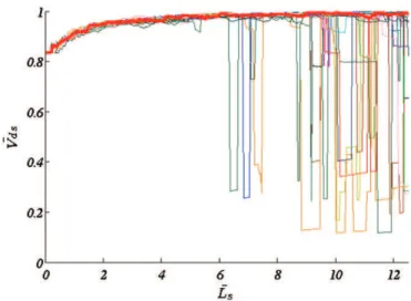
The results are shown onFig. 4. The red curve demonstrates that, when Lsincreases, Vdstends progressively towards 1. In other words,
the cross correlation velocity measured by the dual-slit technique reaches the velocity at the center of the channel when Lsbecomes
suf-ficiently large. Therefore, in the case of large slit separations, i.e. typ-ically larger than 5 times the size of a single particle, the measured velocity directly corresponds to the maximum velocity in the direc-tion parallel to the incident light beam. For smaller values of Ls, the
velocity value measured is smaller.
In fact, when the distance between the slits becomes sufficiently large, the photometric patterns representative of the slow particles become decorrelated between the two slits, leading to a decrease in
Tmaxand an increase in the measured velocity, which progressively
approaches the velocity of the fastest particles (Vmax). In contrast,
for small distances between the slits, every particle, the slowest as well as the fastest ones, contributes to the cross correlation signal. Compared to the case where the slits are sufficiently distant, this in-duces an overestimation of the time shift for which the photometric signals from the two regions have the best match, and leads to an underestimated value of the velocity.
When F and Tacq were increased further, the above results
remained unchanged (data not shown), demonstrating that the cho-sen values were large enough and did not affect the measurement. Influence of frame rate. The results obtained for smaller frame rates (100 to 2000 fps) are also shown onFig. 4. For these values of F, fluctuations occurred around the velocity measured at high frame rates (red curve). Their amplitude decreased with both increasing frame rate and increas-ing slit separation distance. This was because the relative uncertainty on Tmax(=0.5/(FTmax)) and therefore on the measured velocity Ls/Tmax,
increased when the temporal resolution decreased (smaller F) and/or when the slit separation Lsdecreased (smaller Tmax). This effect is
simi-lar to peak-locking in measurements performed by Particle Image Velocimetry (PIV), a spatial correlation technique, where the effect ap-pears when the displacement of particles is small compared to the size of a pixel (Huang et al., 1997; Raffel et al., 2007).
Of course, the value of the temporal resolution for which these fluctuations disappear depends on the flow velocity. In the case illus-trated in Fig. 4, where Vmax= 100 μm/s, fluctuations typically
disappeared above F = 2000 fps. An important question is therefore how to choose an adequate value of F when performing a velocity measurement by the dual-slit technique. We propose an operational criterion, based on the maximum displacement of particles from one image to the next in the sequence. This parameter, denoted Dim,
is equal to Vmaxδ/F and is easily accessible in experiments in vitro or
in vivo. In the case of the reference flow, Dimmust be smaller than
or equal to 0.6 pixels/frame to avoid fluctuations. When 0.6b Dimb 1.2 (pixels/frame), fluctuations are present for small values of Lsbut
they do not interfere with the measurement because they vanish for large values of Ls. As a result, Vdsstill tends towards Vmax (Fig. 4,
green curve: Dim= 1.2 pixels/frame). However, when Dim becomes
too large (Dim> 1.2 pixels/frame in this case), in addition to a large
oscillation amplitude, the evolution of the measured velocity with slit separation exhibits sudden jumps toward smaller values. These sudden jumps are the signature of insufficient statistical convergence
Fig. 4. Normalized dual-slit velocity versus the normalized distance between the two slits for the reference flow parameters (Href= 0.5, Dref= 20 μm, Vref= 100 μm/s, Bref= 1). The results are shown for five frame rates. In all cases, Tacq= 30 s and w = 1 pixel.
of the cross-correlation process (Fig. 4, light blue curve: Dim=
3 pixels/frame).
Influence of acquisition time. Once a sufficiently large F, corresponding to a small Dim, has been chosen, the result of the cross-correlation will
depend on the acquisition time or, in an equivalent fashion, on the number of images in the sequence. To illustrate this, Fig. 5 once again shows the variation of the measured velocity versus the separa-tion between slits, with M varying from 5000 to 150,000 images. As before, when M is very high (See Fig. 5 red curve, where M = 150,000), Vdsreaches 1 when Ls increases. No sudden jump is
ob-served. If M is smaller, however, fewer particles are involved in the recorded signals S1 and S2. In consequence, sudden jumps are ob-served when Ls increases, but, except for these jumps, Vds still
con-verges to 1 (seeFig. 5, purple curve, M = 60,000 images). When M becomes too small, i.e. M≤10,000 images, the measured velocities fluctuate a lot and Vdsno longer reaches 1. Here, the operational
crite-rion regarding the statistical convergence is related to the maximal displacement of particles from the first to the last image in the se-quence, Dacq= MDim. In the case of the reference flow, Dacqmust be
greater than 9,000 pixels to totally avoid sudden jumps (seeFig. 5, red curve), at least if the maximal separation between slits stays in a reasonable range, i.e. below 10 times the particle size. When Dacq
decreases, the number of sudden jumps increases and, for Dacq
below 3600, obtaining a reliable measurement of Vmax becomes
impossible.
In between (3600 bDacqb 9000), the information extracted from the image sequence can be improved by repeating the measurement over multiple pairs of slits, seeThe dual‐slit techniquesection. The ef-fectiveness of this method is demonstrated inFig. 6, where 15 itera-tions of the dual-slit were performed. By iterating the dual-slit several times (thus correlating at different locations on the channel) and choosing the best correlation, the sudden jumps disappear, lead-ing to a smooth evolution of the measured velocity accordlead-ing to the slit separation distance.
This is important because, in practice, it is not always possible to record as many images as needed, depending on the experimental system. A small value of Dimmust be chosen to avoid fluctuations.
On the other hand, a large value of Dacqis needed to avoid losses of
statistical convergence, which imposes a number of images to be
recorded (M = Dacq/Dim) which may be larger than the storage
capac-ity of the camera system.
Effect of slit width. To conclude this study of the reference case, the dual-slit technique was applied for slit widths varying from w = 1 to w = 48 pixels, i.e. ranging from the smallest possible width to the size of two particles. The results are shown inFig. 7. It is noteworthy that, when w increases, the value of Lrefalso increases. Therefore, the
maximum achievable Lsdecreases. However, it has been shown
pre-viously that a large Ls is needed for a relevant implementation of
the dual-slit technique. Moreover, when w increases, the asymptotic value of one is not reached for the largest values of the slit separation distance. This demonstrates that the optimal value of w is the smallest one, i.e. a single pixel. Moreover, in this case, Lref= Lpart, which
facili-tates the interpretation of the results. Influence of flow conditions
This section addresses the question of whether the optimal set of parameters determined above in the flow reference case remains op-timal in other conditions. In particular, the influence of the flow-governing parameters is studied.
The influence of the maximal velocity can be analyzed analytical-ly and will be addressed first. For this purpose, the flow reference case is considered, where F is fixed at any Frefchosen in the optimal
set, i.e. Vrefδ/Frefb 0.6. If the maximal velocity Vrefis multiplied by a
given parameter α, maintaining a constant Dimrequires Frefto be
multiplied by α also. The displacement of any particle from one image to the next in the sequence will then remain unchanged. The resulting image sequence (V = αVref, F = αFref) is similar to the
refer-ence image sequrefer-ence (V = Vref, F = Fref). Thus, the evolution of the
measured velocity as a function of the slit separation distance will be identical to the evolution obtained with Vrefand Fref, as long as
the other parameters are unchanged.2Of course modifying V
ref
with-out simultaneously changing F involves an increase or decrease of Dim. If Dimand Dacqremain in the optimal range (seeTable 2), the
Fig. 5. Normalized dual-slit velocity versus the normalized distance between the two slits for the reference flow parameters (Href= 0.5, Dref= 20 μm, Vref= 100 μm/s, Bref= 1). The results are shown for 5 values of M. In all cases, F = 5000 fps, Dim= 0.06 pixels/frame, and w = 1 pixel. Sudden jumps to infinite values (light blue curve) correspond to situations where autocorrelation dominates (Tmax= 0).
Fig. 6. Normalized dual-slit velocity versus the normalized distance between the two slits, showing the effectiveness of repeating the measurement over multiple pairs of slits. Each curve was obtained for a different longitudinal position of the first slit, 15 equi-spaced values being considered. The bold red curve was obtained, as explained inThe dual‐slit techniquesection, by choosing, among the 15 delays, the one maximiz-ing the correlation for a given Ls. The parameters used for the implementation of the dual-slit technique were: F = 500 fps, M = 15000 images, Dim= 0.3 pixels/frame, Dacq= 4500 pixels, w = 1 pixel, N = 15 and Lp= 48 pixels. The flow-governing param-eters are: Vmax= 50 μm/s, D=30 μm, H=0.53, B=1.
2In particular, if the number M of images in the sequence is unchanged, the optimi-zation parameter Dacqremains constant, as Dacq= MDim.
measurement of Vmaxby the dual-slit technique is still valid. Thus,
modifying the maximal velocity is equivalent to changing the acqui-sition frequency, the effects of which have been described in the pre-vious section.
In the following, the influence of the remaining parameters, i.e. chan-nel depth, D, hematocrit, H, bluntness, B, of the velocity profile is studied, with Vmaxfixed at Vref. All other parameters, except the separation
dis-tance between the two slits, are kept constant (F=1500 fps, Tacq=
30 s, w=1 pixel, δ =3 pixels/μm). With this set of parameters, Dim=
0.2 pixels/frame and Dacq= 9000 pixels.
Fig. 8shows that the influence of the slit separation distance on the measured velocity is independent of D and H. For low values of the hematocrit, however, sudden, large jumps are observed because too few particles travel through the slits, which impair the calculation of the cross-correlation (seeFig. 8, dark blue curve, where H = 0.13). Once again, this can easily be solved by applying the method intro-duced inThe dual‐slit techniquesection and validated in the previous section (seeFig. 6), where the dual-slit measurement is repeated.
In contrast,Fig. 9shows that the degree of bluntness of the veloc-ity profile strongly influences the shape of the curve. As expected, when the velocity profile is flat (B= 0), implying that all the particles travel at the same velocity, the measured velocity corresponds exact-ly to Vmaxregardless of the value of Ls. When B increases
progressive-ly, Vdsreaches Vmaxfor larger slit separation distances because the
fastest particles become relatively less numerous in the channel. Thus, the case of a parabolic profile (B= 1), thoroughly studied in the previous section, is the most unfavorable for the implementation of the dual-slit technique.
All together, the above results demonstrate that, regardless of the flow parameters, the dual-slit technique always allows the maximal velocity in the channel to be measured, provided that the optimal conditions for implementing the technique are used and Lsis in the
range of 5 to 10 particle sizes. In these conditions, summarized in Table 2, Vmaxcan be measured with an error of less than 2%, which
represents the intrinsic error due to the principle of the dual-slit technique.
Dual-slit technique applied to in vitro image sequences
The case of synthetic image sequences of particle flow in microchannels has been carefully studied. However, these image se-quences were generated on the basis of strong assumptions. In partic-ular, the RBCs were considered as rigid tracers, and their interaction with each other and with the wall were not taken into account. Actual blood flows are much more complex. Moreover, the rendering of indi-vidual RBCs (shape and variations in intensity) was considerably sim-plified in the synthetic images. The question of whether the results obtained using sequences of synthetic images are relevant in the con-text of in vitro experiments or not is therefore examined in the pres-ent section.
First, it is useful to recall that, while synthetic images represent the channel in a plane parallel to the light beam, the experimental im-ages of in vitro flows are in a plane perpendicular to the light beam (seeFig. 1).
Therefore, unlike previously, the height of the slits, h, is not set to 1 pixel. As the signals extracted from experimental images contain some noise, slightly increasing the height of the slits improves the correlation. In all that follows, the height of the slits is fixed at 3 pixels. As this value is smaller than the size of a single RBC, it is still possible to determine the velocity variations in the transverse di-rection of the channel.
Fig. 7. Normalized dual-slit velocity versus normalized distance between the two slits for the reference flow parameters (Href=0.5, Dref=20 μm, Vref=100 μm/s, Bref=1), showing the influence of the slit width. The parameters used for the implementation of the dual-slit technique are: F=1000 fps, Tacq=30 s, Dim=0.3 pixels/frame, and Dacq=9000 pixels.
Table 2
Operational parameters for an optimal implementation of the dual-slit.
F (fps) M (images) w (pixels) Ls
Dim¼VmaxFδb0:6 Dacq= MDim≥9000 w = 1 5 to10
particle sizes
Fig. 8. Normalized dual-slit velocity versus normalized distance between the two slits, for various values of H and D. The parameters used for the implementation of the tech-nique were: F = 1500 fps, M= 45000 images, and w = 1 pixel with the flow conditions Vmax= 100 μm/s and B =1.
Fig. 9. Normalized dual-slit velocity versus normalized distance between the two slits for various values of B from 0 to 1. The parameters used for the implementation of the technique were: F = 1500 fps, M= 45000 images, and w = 1 pixel with the flow conditions Vmax= 100 μm/s, D=20 μm, and H=0.5.
Several cases are considered:
• RBCs flowing in single file in a square 10 μm× 10 μm channel at high feed hematocrit (HD= 0.5),
• Flow in a larger rectangular channel (100 μm× 20 μm) at lower feed hematocrit (HD= 0.2),
• Flow in a square channel of the same depth (i.e. 20 μm ×20 μm) at HD= 0.4.
In the first case, a flat velocity profile is expected. In the second case, in a similar experimental configuration (Lima et al., 2008), the RBC maximal velocity profile in the Ox direction was reported to be markedly blunt in the central region, mainly due to the low aspect ratio of the channel.
In all cases, images were 512 pixels long and the measurement was repeated over multiple pairs of slits (N = 10 and Lp= 40 pixels).
Plots of experimental Vdsversus Lswith slits positioned along the
cen-terline of the channel are shown inFigs. 10a, b and c (red curves) for the three cases studied.
In all cases, the variation of Vdswith the slit separation distance
was very close to that already observed when using synthetic image sequences: global increase of Vdswith a concomitant decrease in the
observed fluctuations and existence of an asymptotic regime at large separation distances. This important result demonstrates that all the main features of the influence of the slit separation distance were captured in the previous simplified analysis. Thus, in experi-ments in vitro, the highest value of the measured velocity for Ls
be-tween 5 and 10 RBC sizes can be considered as the maximal RBC velocity in the direction parallel to the light beam. Quantitatively, the measured values of the maximal velocity were 495, 542 and 1278.5 μm/s in the three examples shown in Figs. 10a, b and c, respectively.
The corresponding transverse velocity profiles are plotted on Figs. 11a, b and c. For each measurement along the x axis, plots of Vdsversus Lswere examined to ensure that fluctuations or sudden
jumps did not significantly affect the result. As previously, the mea-sured velocity was chosen to be the maximum of Vdsvalues for Ls
be-tween 5 and 10 RBC sizes. As expected, a flat transverse velocity profile was obtained in the smallest channel (B =0.04 by least square adjustment to Eq.(7), seeFig. 11a). In addition, in the rectangular channel, a markedly blunt profile was obtained in the central region. This result is consistent with the results obtained by Lima et al. (2008)using a micro-PIV system. However, the present analysis pro-vides a significantly higher spatial resolution, especially near the walls. Thus, it is possible to evaluate the maximal sliding velocity of the RBCs at the channel walls (200 μm/s in the present case, i.e. 39% of the velocity at the channel center). Finally, in the 20 μm × 20 μm square channel, the RBC velocity profile exhibited a larger sliding ve-locity with quite a small bluntness parameter (B = 0.19 by least square adjustment to Eq.(7), seeFig. 11c).
Therefore, the dual-slit technique clearly appears to be a powerful and straightforward technique for the quantitative determination of the RBC maximal velocity profile in the transverse direction in microchannels. The useful information lies in the asymptotic value of the measured velocity (Vds) for large slit separation distances.
Below, we show that additional information on the shape of the velocity profile in the direction parallel to the light beam can be extracted from the behavior of Vdsat small to moderate separation
distances. To that end, results obtained in square channels, where identical profiles of maximal velocity can be expected in both Ox and Oy directions, are useful. In this case, it is possible to generate synthetic sequences of images for which the imposed velocity profile matched the experimental one (i.e. identical values of Vmaxand B in
Eq.(7)). The behavior of the measured velocity versus the slit separa-tion distance, with F, M, δ, H and D chosen to reproduce the experi-mental conditions, is represented in Figs. 10a and c (dark blue
Fig. 10. Dual-slit velocity measured at the center of the channel (x = 0) versus the distance between the two slits for sequences of in vitro and synthetic images. a) 10 μm ×10 μm in vitro channel. For the three sequences: F =3000 fps, M=40000 images, HD= 0.5, D = 10 μm, δ= 3 pixels/μm, w=1 pixel. Moreover, in vitro: ΔP = 12 mbar and h = 3 pixels. For the synthetic image sequences, Vmax= 495 μm/s. b) 100 μm ×20 μm in vitro channel. For the three sequences: F =2000 fps, M= 20000 images, HD= 0.2, D = 20 μm, δ=2.79 pixels/μm, w=1 pixel. Moreover, in vitro: ΔP= 2.5 mbar and h = 3 pixels. For the synthetic image sequences, Vmax= 542 μm/s. c) 20 μm × 20 μm in vitro channel. For the three sequences: F=4000 fps, M= 30000 images, HD= 0.4, D = 20 μm, δ=2.9 pixels/μm, w= 1 pixel. Moreover, in vitro: ΔP = 13.5 mbar and h = 3 pixels. For the synthetic image sequence, Vmax= 1278.5 μm/s.
curves). For comparison purposes, the curves obtained for synthetic image sequences corresponding to a parabolic velocity profile are displayed on the same figures (light blue curves). In both cases, the behavior of Vdsas a function of Lsat small to moderate separation
dis-tances is closer to the experimental behavior when the synthetic pro-file matches the experimental one. To quantify this, the normalized mean square differences between the measured velocities for syn-thetic image sequences and the corresponding images recorded in vitro were calculated for all Ls below 40 μm. In the case of the
10 μm × 10 μm microchannel, these differences were 0.23 for B = 1 and 0.06 for B = 0. Similarly, for the 20 μm × 20 μm channel, the er-rors were 0.35 for B = 1 and 0.11 for B = 0.19.
In the case of the high-aspect-ratio rectangular channel, the as-sumption that the (unknown) velocity profile in the (small) channel depth is close to the velocity profile in a square channel of the same size, even if quite rough, can be made. The results obtained with the corresponding bluntness parameter (B = 0.19) are plotted in Fig. 10b (dark blue curve). Once again, the comparison with the ex-perimental behavior is much better than when a parabolic velocity profile is assumed. The normalized mean square differences are 0.42 and 0.05 for B = 1 and B = 0.19, respectively.
Discussion and conclusion Main findings of the study
As indicated in the Introduction, the objectives of the present study were twofold.
Firstly, we aimed to understand the physical signification of the cross-correlation velocity measured by the dual-slit technique in sit-uations where the flow showed velocity gradients, the shapes of which were, a priori, unknown. In this framework, the main result of this paper is the following. Provided the distance between the two slits is large enough for the slowest RBCs to “decorrelate” and small enough to avoid complete loss of correlation, the cross-correlation velocity measured by the dual-slit technique corresponds to the maximal velocity in the direction parallel to the light beam. This distance is typically between 5 and 10 times the characteristic size of a single RBC. Moreover, the results obtained suggest that studying the variations of the measured velocity versus the slit sepa-ration distance at small to moderate sepasepa-ration could provide qualita-tive information on the shape of the velocity profile in the same direction.
Secondly, we aimed to determine a robust way of choosing the ex-perimental parameters to allow this maximal velocity to be measured with high accuracy. These parameters are summarized inTable 2.
The present discussion is organized as follows. Firstly, the validity of the approach chosen in order to overcome the lack of knowledge about the RBC velocity profile, i.e. comparison of the results obtained using simplified synthetic image sequences and in vitro movies of flowing RBCs, will be discussed. Secondly, the impact of the choice of the slit separation distance on the results of a dual-slit measure-ment and the corresponding conversion factor usually used to deduce the mean velocity and flow rate will be addressed. Then, the practical robustness and the limitations of the optimized dual-slit technique will be presented. Finally, the implications of the above results in the field of microvascular research will be highlighted.
Validity of the present approach
The synthetic sequences of images used to validate and optimize the dual-slit technique are a very rough representation of blood flow. Firstly, the rendering of RBCs on real image sequences is much more complex, with shapes more complicated than ellipsoids, and with variations in gray level depending on their orientation relative to the light beam. Secondly, at large concentration, several RBCs
Fig. 11. Maximal velocity profiles obtained by dual-slit in the transverse direction of in vitro channels. In all cases, the dual-slit was implemented using w = 1 pixel and h = 3 pixels. The error bars represent the cumulated contributions of the intrinsic error due to the principle of the dual-slit technique (2%) and the experimental uncer-tainties. The latter (~3%) include the uncertainties on Lsand Tmax(1 pixel and 1/F, respectively) and the relative uncertainty on δ (~1%). These three contributions are of the same order. a) 10 μm ×10 μm channel, F= 3000 fps, M= 40000 images, HD= 0.5, D = 10 μm, δ=3 pixels/μm, ΔP =12 mbar. The least square adjustment to Eq.(7)yields B = 0.039 and Vmax= 499.3 μm/s. b) 100 μm × 20 μm channel, F =2000 fps, M= 20000 images, HD= 0.2, D = 20 μm, δ= 2.79 pixels/μm, ΔP =2.5 mbar. c) 20 μm ×20 μm channel, F =2000 fps, M=20000 images, HD= 0.4, D = 20 μm, δ= 2.9 pixels/μm, ΔP =13.5 mbar. The least square adjustment to Eq. (7)yields B = 0.19 and Vmax= 1305.5 μm/s.
may overlap in the optical path, with a non-linear light attenuation (Pries et al., 1983). In addition, in this case, the estimation of the resulting hematocrit as the ratio between the area occupied by the synthetic particles and the total area of the channel is a mere approx-imation. Finally, the dynamical effects induced by RBCs (deformation, hydrodynamic interactions between RBCs or with the vessel wall) are ignored, even though these effects induce a faster deformation of the patterns formed by the RBCs inducing faster losses of correlation be-tween the two slits.
Despite these strong simplifications, the results obtained by dual-slit with real image sequences of RBCs flowing in a microchannel closely match the results obtained using synthetic image sequences. In particular, the variations of the measured velocity with the slit sep-aration distance, which contains all the useful information necessary to interpret the results of a dual-slit measurement, are identical. Moreover, our results demonstrate that these variations are indepen-dent of both hematocrit and height of the channel. In consequence, any uncertainty on their values does not impair the measurement, which, a posteriori, validates the use of a very rough representation of individual RBCs in our synthetic images generator.
Altogether, by going back and forth between synthetic and real in vitro image sequences, the above results demonstrate that the dual-slit technique can be used for measuring the maximal RBC veloc-ity in the depth of a microchannel. This is consistent with previous theoretical work on the influence of slit separation distance (Lee and Duling, 1989), see below.
Influence of slit separation distance
To our knowledge, the influence of the slit separation distance (Ls)
was first studied bySilva and Intaglietta (1974), who focused on the degree of correlation between the upstream and downstream signals. By performing intravital experiments on cat microvessels, they dem-onstrated that the value of the correlation peak decreased monoton-ically with increasing slit separation distance. In fact, the farther apart the slits were, the more the traveling RBCs changed shape and orientation, with subsequent modifications of their contribution to the light modulation between the slits. In addition,Intaglietta et al. (1975) suggested that, while choosing small separation distances maximizes the cross-correlation, too-small distances induce addition-al autocorrelation in the caddition-alculation. Consequently, they recom-mended that the spacing between the two slits should be at least one RBC size, which, given our results, is still insufficient.
Lee and Duling (1989)reexamined the influence of Lson the
mea-sured velocity. To do so, they assumed a Poiseuille flow and that the light signal received by the first slit, a photodiode, was a sine function. In this case, using the indicator dilution theory in the frequency do-main, they analytically demonstrated that the signal in the second slit was also a sinusoid, attenuated from the input and shifted in phase. They argued that the corresponding time delay was the time maximizing the cross correlation between both slits, and computed it from the previous analytical results as a function of the slit separa-tion distance and the frequency of the input signal. However, Lee and Duling chose to non-dimensionalize the resulting velocity using the mean velocity. In other words, following previous authors, they fo-cused on determining the empirical conversion factor, i.e. the ratio of the measured velocity (Vds) to the mean velocity (Vmean).
Consequently, while they reached the correct conclusion that, for a large dimensionless time delay between the two slits, i.e. for asymptot-ically large slit separation distances and/or high frequency photometric signals, the measured velocity asymptotically approached the maximal velocity, they did not take advantage of this result for practical pur-poses. On the other hand, they demonstrated that, when this dimen-sionless time reached zero, i.e. the spacing between the slits was made infinitesimal and/or the photometric signals were composed of low fre-quency fluctuations, the measured velocity corresponded to the mean
velocity. In between, they demonstrated that the measured to mean ve-locity ratio increased monotonically. Altogether, their results suggest that, in order to perform a velocity measurement by dual-slit that is di-rectly related to an actual velocity flow scale (i.e. mean or maximal ve-locity), asymptotically small or large slit separation distances must be used. In real experiments, however, the light signals are not ideal sinu-soids and autocorrelation dominates for the calculation of the cross-correlation at small separations. Therefore, within this limit, the corresponding time delay equals zero, leading to an undetermined value of the measured velocity. Moreover, at small separation distances, fluctuations induced by insufficient acquisition frequencies are maxi-mal, which renders the small separation distance limit unsuitable for practical purposes. Consequently, consistently with our approach, large slit separations must be considered in order to measure the RBCs' maximal velocity. Of course, the drawback is that the degree of correlation decreases monotonically with the slit separation distance. In other words, in practice, a high degree of correlation does not guaran-tee a correct and meaningful measurement. Our study indeed has shown that, in the large separation limits, the correlation is sometimes lost. This leads to sudden jumps in the variations of the measured veloc-ity versus the slit separation distance, which can be easily detected. In this case, the statistical convergence can be improved by repeating the measurement over multiple locations along the channel (see The dual‐slit techniquesection).3
Conversion factor and velocity profile
Because flow rate is one of the most important physiological pa-rameters and because of the uncertainties on the actual signification of the measurement provided by the dual-slit technique,Baker and Wayland (1974)performed a detailed experimental study using con-trol experiments with prescribed flow rate. They concluded that the flow rate, within 10% error, corresponded to the measured centerline velocity divided by a factor 1.6 and multiplied by the tube cross sec-tion, in tubes less than 90 μm in diameter. They presented an averag-ing model (see Eq. (1)) in an attempt to take account of the modulation of light by concentric laminae of RBCs moving at different velocities to explain the 1.6 conversion factor. With this model and assuming a parabolic velocity profile and a negligible transverse ex-tent of the sensing region, the centerline velocity measured by dual-slit should be 1.6 times the mean velocity, in accordance with their experimental results. However, this averaging approach is not able to reproduce the strong dependence of the conversion factor on the slit separation distance, i.e. the monotonic increase from 1 to 2, theoretically predicted byLee and Duling (1989) and confirmed in the present work in both synthetic and real experiments. This dem-onstrates that the Baker and Wayland averaging approach is incor-rect, the factor 1.6 being obtained by chance in the admissible range. Nevertheless, this conversion factor is still used to relate the mean flow velocity and the velocity measured by dual-slit for investi-gations of blood microcirculation, see, e.g.,Ong et al. (2012).
Moreover, the Baker and Wayland assumption of a Poiseuille ve-locity distribution for the RBCs is invalidated by the present results, which demonstrate the relevance of Eq.(7)(Pittman and Ellsworth, 1986) for describing the blunt velocity profile of RBCs measured at midplane in square channels. Compared to previous works (Baker and Wayland, 1974; Gaehtgens et al., 1970b; Lima et al., 2008; Sherwood et al., 2012), the present analysis provides much higher spatial resolution for the velocity measurement, especially near the
3Note that, the degree of correlation decreased faster in our experiments in vitro than when studying synthetic image sequences. This is consistent with a faster defor-mation of the RBC patterns induced by their defordefor-mation and by hydrodynamic inter-actions. Counteracting these effects, RBC aggregation is likely to improve the patterns stability over time. Moreover, the non-uniform distribution of aggregate size is likely to increase the variety of patterns which should improve the quality of the correlation.
walls. Thus, for the first time, it is possible to measure the maximal sliding velocity of the RBCs at the channel walls, with great accuracy, in various flow configurations and to deduce the bluntness parameter without any further assumption regarding the boundary conditions.
Nevertheless, despite these improvements, information on both the hematocrit distribution and the velocity of plasma relative to RBCs, especially near the channel wall, is still lacking for the evalua-tion of the flow rate.
Robustness and limitations of the DS technique
When the dual-slit technique needs to be applied, the optimal conditions for measuring the maximal velocity cannot always be sat-isfied. In particular, the choice of photosensor size and/or spacing may be limited by the kind of photosensors that are used: phototransistors (Baker and Wayland, 1974; Gaehtgens et al., 1970a), photodiodes (Pries et al., 1989; Sapuppo et al., 2007; Silva and Intaglietta, 1974), optical fibers (Lee and Duling, 1989), or areas of interest in digitized image sequences (Intaglietta et al., 1975; Liu et al., 2009). Whatever the photosensors used, the present results demonstrate that their width (transverse extent) should be small compared to the size of an RBC, as also suggested byIntaglietta et al. (1975). This is easily achieved when using digitized image sequences of RBCs, as in the present work, and leads to a very good spatial resolution, typically 0.3 μm in the present study. In contrast, the use of photosensors that are large compared to the channel width averages the light modulations over large regions and greatly reduces the sensitivity of the dual-slit method, thus producing signif-icant distortions in the measured velocity profiles, especially in re-gions of large transverse velocity gradients, typically near the walls (Baker and Wayland, 1974).
Moreover, when using video image sequences, the separation be-tween the two slits can be varied, which provides valuable informa-tion on the validity of the measurement (see below), and allows the measurements to be repeated over multiple slit locations to improve statistical convergence.
In this case, the dual-slit appears to be a precise (less that 5% error, seeFig. 11and legend), robust method for measuring the maximal velocity in the direction parallel to the light beam, especially for in vitro applications. Our results demonstrate that the measurements are independent of the shape of the velocity profile, the hematocrit and, provided that the depth of field of the optical set-up is sufficient, the depth of the channel.
Several limitations must, however, be highlighted as far as in vivo RBC flows are concerned. First, the vessel must be sufficiently straight and long for the distance between the two slits to be satisfactory for the application of the technique. Second, it is not possible to measure unsteady flows because of the need for time averaging to ensure statis-tical convergence. In contrast, the shape of the channel cross-section certainly has no effect on the dual-slit results. Moreover, the shape of
RBCs flowing in PDMS microchannels and in the actual in vivo microcir-culation is very similar (Shevkoplyas et al., 2003). This suggests that the optimized dual-slit technique can also be useful for measuring time-averaged velocities in vivo.
Implications in microvascular research
Many pathophysiological studies have measured the velocity of RBCs using the dual-slit technique. Most of the time, they were based on previous metrological works, which are summarized in Table 3. However, even in these works with a metrological focus, the parameters used for the implementation of the dual-slit tech-nique have never been optimized. As a result, none of these studies fulfilled all the criteria defined inTable 2. In particular, LSdid not
ex-ceed the size of one RBC for most of these studies, which implies that the asymptotic value of Vmaxwas not reached. Also, the frame rate and
acquisition time proved to be small with respect to the measured ve-locity range.
While the order of magnitude of the errors in these previous works is difficult to quantify, mainly because some of the relevant quantitative information is missing, the data collected inTable 3 sug-gest that the errors on the measured velocities were not negligible. In fact, in the present work, large fluctuations of the measured velocity were observed when the parameters used were far from the optimal conditions (e.g. inFig. 4). This may explain why significant inaccura-cies in the interpretation of in vivo photometric measurements, up to a factor 10 for blood flow rate measurements, have already been identified byCokelet et al. (1998), who aimed to quantify the mea-surement errors by evaluating the deviation from mass conservation. To conclude and sum up, a detailed analysis of the dual-slit tech-nique has been performed using synthetic image sequences representing the flow of RBCs in a plane parallel to the light beam di-rection, i.e. images which are inaccessible to the observer in experi-ments in vitro or in vivo. This parametric study has identified the optimal conditions for using the dual-slit technique and determined the operational criteria that must be fulfilled to satisfy them. In this case, the measured velocity has been shown to be the maximal veloc-ity in the direction parallel to the light beam, whatever the flow rate, hematocrit and channel depth. This optimized dual-slit technique was then validated using in vitro image sequences, permitting the profile of maximal RBC velocity across the channel to be measured. These profiles are blunter than a parabolic profile, and have a non-zero sliding velocity at the channel walls.
Acknowledgments
We gratefully acknowledge D. Bourrier, M. Dilhan and P. Joseph from LAAS-CNRS, Toulouse for their help in the microfabrication and microfluidic experiments, and Sébastien Cazin from IMFT for his help in image acquisition and post-processing. We also thank Susan
Table 3
Parameters used in previous studies for dual-slit implementation.
Authors Ls(RBC size) F (Hz or fps) Tacq(s) w (μm) h (μm) Vdsrange
(mm/s)
Conversion factor (Vds/Vmean) a) In vivo studies
Gaehtgens et al. (1970a) n/a 120 12.5 × 10⁻³–0.125 n/a n/a ~1.7–30 n/a
Silva and Intaglietta (1974) 0.5–9 n/a ~20 2.5–5 n/a ~3 n/a
Intaglietta et al. (1975) ~1 ≤30 n/a b8 n/a 0.6–3 n/a
Pries et al. (1989) b1 n/a n/a ~8 ~8 n/a 1.64–1.8
Lee and Duling (1989) b1 6200 0.2 2.5 4.7 ~1 ~1.58
Liu et al. (2009) ~1 2000 10 1 pixel = vessel diameter 0.7–2.6 n/a b) In vitro studies
Baker (1972) ~1 ≤500 n/a 2–5 2–5 1–50 1.6
Lipowsky et al. (1980) ~1 n/a n/a ~8 ~8 n/a n/a