This is an author-deposited version published in:
http://oatao.univ-toulouse.fr/
Eprints ID: 5685
To link to this article:
DOI:10.1016/J.IJHYDENE.2010.05.101
URL:
http://dx.doi.org/10.1016/J.IJHYDENE.2010.05.101
To cite this version:
De Silva Munoz, Leonardo and Bergel, Alain and Féron,
Damien and Basséguy, Régine (2010) Hydrogen production by electrolysis of a
phosphate solution on a stainless steel cathode. International Journal of
Hydrogen Energy pp. 8561-8568. ISSN 0360-3199
O
pen
A
rchive
T
oulouse
A
rchive
O
uverte (
OATAO
)
OATAO is an open access repository that collects the work of Toulouse researchers and
makes it freely available over the web where possible.
Any correspondence concerning this service should be sent to the repository
administrator:
[email protected]
Hydrogen production by electrolysis of a phosphate solution
on a stainless steel cathode
Leonardo De Silva Mun˜oz
a,1, Alain Bergel
a, Damien Fe´ron
b, Re´gine Basse´guy
a,*
aLaboratoire de Ge´nie Chimique (CNRS-Universite´ de Toulouse), 4 alle´e Emile Monso, 31432 Toulouse cedex 4, FrancebService de la Corrosion et du Comportement des Mate´riaux dans leur Environnement, CEA-Saclay, 91191 GIF-SUR-YVETTE Cedex, France
a b s t r a c t
The catalytic properties of phosphate species, already shown on the reduction reaction in anaerobic corrosion of steels, are exploited here for hydrogen production. Phosphate species work as a homogeneous catalyst that enhances the cathodic current at mild pH values. A voltammetric study of the hydrogen evolution reaction is performed using phosphate solutions at different concentrations on 316L stainless steel and platinum rotating disk electrodes. Then, hydrogen is produced in an electrolytic cell using a phos-phate solution as the catholyte. Results show that 316L stainless steel electrodes have a stable behaviour as cathodes in the electrolysis of phosphate solutions. Phosphate (1 M, pH 4.0/5.0) as the catholyte can equal the performance of a KOH 25%w solution with the advantage of working at mild pH values. The use of phosphate and other weak acids as catalysts of the hydrogen evolution reaction could be a promising technology in the development of electrolysis units that work at mild pH values with low-cost electrodes and construction materials.
1.
Introduction
In the global energy context, increased needs, security of supplies and environmental risks (carbon dioxide emissions and global warming) must be taken into consideration. Further research has therefore to be developed, focusing on diversification and the use of optimal primary resources (fossil, nuclear, sustainable, etc.). The synthetic fuel mainly considered is hydrogen, which could make up the future energy vector for supplying power to the various sectors of industry, as it allows energy to be stored and distributed under very flexible conditions with low pollution[1]. Hydrogen is the most abundant element on our planet (in water), but the molecule is not available directly in the natural world. To be economically and ecologically feasible, the massive use of
hydrogen as an energy source (thermal or electric) depends upon the development of all steps of the process (production, storage, distribution). Its production by electrolysis using electricity coming from sustainable sources such as sun, wind or sea power is certainly the most elegant solution for storing energy. Currently, most of the industrial production of hydrogen through water electrolysis is performed using aqueous KOH (30%w) at 80!C and applying a cell potential from 1.65 to 1.8 V[2]. Research on alkaline electrolysis has mainly focused on investigating materials for electrocatalysis in order to increase current density and life span. Nickel based alloys deposited on the electrode surface are the most commonly used as electrocatalysts[3,4]. Currently, some new research shows that less technical quality materials can be used as cathodes to reduce the equipment cost[5,6].
* Corresponding author. Tel.: þ33 (0) 534615251; fax: þ33 (0) 534615253. E-mail address:[email protected](R. Basse´guy).
In the domain of electro-analysis, many papers have shown that weak acids may act as homogeneous catalysts for hydrogen evolution. The most widely accepted mechanism for the reduction of weak acids is of the chemicaleelectrochemical (CE) type, where the dissociation of the acid takes place before the electrochemical reduction of free protons[7e9]:
HB $ HþþB# (1)
2Hþþ2e#$H
2 (2)
The dissociation step for most weak acids is considered to be very rapid because, in most cases, no chemical limitation is found.
An alternative mechanism has been proposed by other authors who claim that the hydrogen atoms of undissociated weak acids (HB) could be directly reduced without a dissocia-tion step [10e13]. Stojek et al. [13]studied the influence of a supporting electrolyte in the reduction of polyprotic acids on platinum electrodes. They proposed that, after the electro-chemical reduction of the undissociated acid in the presence of a supporting electrolyte, the conjugate base of the acid (B#)
reacted with water or with protons (Hþ) to re-establish the
acidebase equilibrium in the solution. O’Neil et al.[14]and Takehara et al. [15] showed that hydrogenated phosphate species may undergo an electrochemical deprotonation on platinum electrodes and Da Silva et al.[10]showed that this electrochemical deprotonation of phosphate was possible on stainless steel electrodes according to the following reaction mechanism:
A two step electrochemical reduction:
H2PO4#þe#$HadþHPO42# (3)
HadþH2PO4#þe#$H2þHPO42# (4)
2Had$H2 (5)
coupled with the acidebase equilibrium:
HPO42#þH2O $ H2PO4#þOH# (6)
This type of reaction system is normally known as a cata-lytic ElectrochemicaleChemical (EC’) mechanism [16]. It should be noted that coupling reactions (3) and (4) with the acidebase equilibrium of phosphoric acid (6) leads to water reduction as the global reaction:
2H2O þ 2e#$H2þ2OH# (7)
The experimental data and the theoretical model proposed by Da Silva et al. in their corrosion studies showed that a significant quantity of molecular hydrogen was produced by this mechanism[10].
The objective of this work was to test phosphate species as catalysts of water electrolysis for hydrogen production. A voltammetric study of the hydrogen evolution reaction was performed using phosphate solutions at different concentra-tions on stainless steel and platinum rotating disk electrodes. Then, hydrogen was produced in an electrolytic cell using various experimental conditions (various anodic and cathodic electrolytes) to evaluate the potential of the phosphate solu-tion as a new catholyte for hydrogen producsolu-tion. Particularly, the performance of the system was compared to classical alkaline electrolysis by using a 25%w KOH solution.
2.
Materials and methods
2.1. Chemicals
The chemical substances used in the experiments were: dihydrogen potassium phosphate (KH2PO4, Prolabo),
potas-sium chloride (KCl, Sigma Aldrich), hydrochloric acid (HCl, Acros Organics), potassium hydroxide (KOH, Prolabo), and deionised water (ELGA PURELAB Option-R, 10e15 MU cm).
2.2. Voltammetric study
The experiments were performed in a three-electrode cell (Metrohm) using a Solartron 1286 potentiostat controlled by the ‘Corrware’ software. The working electrode was a rotating disk made of platinum (2 mm diameter) or AISI 316L stainless steel (5 mm diameter, composition in percentage: C 0.03; Cr 17; Fe 65; Mn 2; Mo 2.5; Ni 12; S 0.03; P 0.045; Si 1) embedded in Teflon"
. Both rotating electrodes were purchased from Radio-meter. The rotation speed was controlled by a Radiometer CTV101 speed control unit. The counter-electrode was a grid made of a platinumeiridium alloy (10% iridium, from Patecxis, France) and a saturated calomel electrode (SCE) was used as the reference electrode (Radiometer Analytical). Experiments were carried out in solutions containing 0.1 M potassium chloride as the supporting electrolyte and different phosphate concentrations at pH 8.0. Before each voltammetric experi-ment, the working electrode was polished with a 1 mm grade abrasive sheet (3M 262x Imperial) and then ultrasonically cleaned in deionised water for 5 min to eliminate any pollu-tion. Before the electrode was introduced into the cell, the solution was deoxygenated with a nitrogen gas flux for 15 min. The nitrogen flux was maintained above the solution throughout the experiment. Then, with a rotation speed of 1000 rpm, the linear voltammetry curves were recorded at 20 mV s#1from #0.1 V vs. SCE for the platinum electrode and
from #0.5 V vs. SCE for the stainless steel electrode to #1.1, #1.3 or #1.5 V vs. SCE.
2.3. Electrochemical production of hydrogen
Experiments were performed in a Plexiglas filter-press type reactor with two 90 cm3compartments separated by a Nafion"
N417 membrane (DuPont). The measurements were made by imposing a constant cell voltage or current using a Solartron 1286 potentiostat controlled by the ‘Corrware’ software. The cell voltage and current were measured with the potentiostat
while the cathodic and anodic potentials were measured separately using multimeters (Fluke) with two saturated calomel electrodes (Radiometer) connected to the corres-ponding compartment by a luggin capillary. The 316L stainless steel (composition in percentage: C 0.019, Cr 17.3, Mo 2.04, Ni 11.3, Mn 1.04, N 0.041, Fe bulk) cathode (20 cm2) was polished
with abrasive paper from grades P600 to P2400 (Lam-Plan). The anode was a platinumeiridium alloy grid (10% iridium, from Patecxis, France) with a projected area of 20 cm2. Temperature
was measured with a digital thermometer (TP3001) and pH with a combined pH electrode (Radiometer). The cathodic compartment was hermetically closed and equipped with an outlet tube that collected the hydrogen produced in an upside down 10 mL graduated glass cylinder filled with water. Precautions were taken to avoid over-pressure in the reactor.
3.
Results and discussion
3.1. Voltammetric study
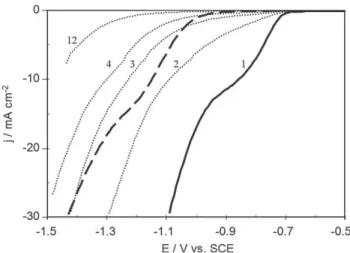
Figs. 1 and 2show the linear voltammetry curves made with platinum and stainless steel rotating disk electrodes (1000 rpm) using different phosphate concentrations at pH 8.0 with KCl 0.1 M as supporting electrolyte. In the presence of phosphate, a reduction wave was observed, starting at approximately #0.7 V vs. SCE for platinum (Fig. 1) and #0.9 V vs. SCE for stainless steel (Fig. 2). For both electrodes, the current density values of the waves were of the same order of magnitude with the same concentration of phosphate, as shown onFig. 3for 0.5 M phosphate solution. The reduction current density depended strongly on phosphate concentration. Insets inFigs. 1 and 2show a linear relationship between current density and phosphate concentration at #0.85 and #1.20 V vs. SCE for the platinum and stainless steel electrodes respectively.
The results clearly show that the cathodic wave corres-ponds to the reduction of a species whose concentration is directly proportional to the phosphate content in the solution.
At constant pH, the increase in the cathodic current with total phosphate concentration cannot be attributed to an increase in proton concentration, which remained the same in each experiment. Furthermore, at pH 8.0 the proton concentration was too small to explain the high current obtained. The current density augmentation has been explained in other works by the electrochemical deprotonation of phosphate
[10,17]. At this pH, the predominant phosphate species involved in the reduction reaction were H2PO4#and HPO42#(14
and 86% of total phosphate respectively). Daniele et al. [8]
found that the reduction curves of weak acids appeared at less negative potentials as the dissociation constant of the
Fig. 1 e Linear voltammetry curves with the platinum rotating disk electrode (1000 rpm, 20 mV sL1) at different
phosphate concentrations (KCl 0.1 M as supporting electrolyte, pH 8.0). Inset, current density vs. phosphate concentration at L0.85 V vs. SCE.
Fig. 2 e Linear voltammetry curves with the stainless steel (316L) rotating disk electrode (1000 rpm, 20 mV sL1) at
different phosphate concentrations (KCl 0.1 M as supporting electrolyte, pH 8.0). Inset, current density vs. phosphate concentration at L1.2 V vs. SCE.
Fig. 3 e Linear voltammetry curves with platinum (d and ..) and stainless steel (d d) rotating disk electrodes (1000 rpm, 20 mV sL1) in phosphate 0.5 M, KCl 0.1 M at pH
8.0. Numbers beside the curves for platinum correspond to the scan number. Only one curve with stainless steel is presented as all the obtained curves had no significant difference between them for up to 4 consecutive potential scans.
acid increased. As H2PO4#has a higher dissociation constant
than HPO42# (10#7.21 for H2PO4# and 10#12.33 for HPO42# [18]),
H2PO4#would be easier to reduce and should be the species
involved in the formation of the reduction wave.
Fig. 3 presents successive linear voltammetry curves (20 mV s#1) obtained with platinum and stainless steel
elec-trodes in a 0.5 M phosphate, 0.1 KCl solution at pH 8.0. The curves show an evolution of the platinum electrode behaviour that renders it less and less active, shifting the curves towards more negative potentials. The curves also show an alteration on the reaction mechanism since the reduction wave disap-pears after the first polarization. In contrast, the stainless steel electrode did not show any evolution during the successive potential scans. It remained stable reproducing the same curve, shown inFig. 3, which had higher values than those obtained with the poisoned platinum electrode after 3 or more scans. These various behaviours can be explained by some differences in adsorption phenomena of phosphate species on platinum and stainless steel: an irreversible adsorption on platinum may lead to poisoning the electrode whereas the adsorption/desorption may be reversible on stainless steel.
3.2. Electrochemical production of hydrogen
3.2.1. Potentiostatic electrolysis
The production of hydrogen was performed in a filter-press type reactor with two 90 cm3 compartments separated by
a Nafion"
N417 membrane, using a stainless steel plate (AISI 316L) as the cathode and a platinum grid as the anode. The electrolyte was a 0.5 M phosphate solution at pH 8.0 with 0.1 M KCl as supporting electrolyte. Control experiments were per-formed with a phosphate-free 0.1 M KCl solution at pH 8.0. The electrolysis was achieved by imposing a cathodic potential of #1.1 V vs. SCE on the stainless steel cathode with respect to the reference electrode of the cathodic compartment. This potential was chosen because it was situated in the area where the influence of the phosphate species on the hydrogen evolution was the best highlighted: it is related to the middle of the cathodic wave observed inFig. 2.
The current density (cathodic negative values) was found, as expected, to be higher when phosphate species were present than in the control experiment without phosphate
(Fig. 4). During the first 5 min of electrolysis, the current densities decreased rapidly (in absolute value) for both solu-tions, corresponding to the reduction of the dioxygen present in the compartment. After this, the current density for the phosphate-free solution drifted slowly from #0.39 mA cm#2to
#0.16 mA cm#2. In the phosphate solution, the current density
remained relatively stable around #1.35 mA cm#2during the
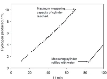
100 min of electrolysis, presenting only some minor oscil-lating variations. In the presence of phosphate, the hydrogen production rate was approximately 10 mL h#1 (T ¼ 298 K,
P ¼ 101.3 kPa) (Fig. 5) whereas the phosphate-free solution gave no measurable production of hydrogen.
After 100 min, the total electricity consumed was 156.6 C in the presence of phosphate, which corresponded to a faradic efficiency of 91.4% with respect to hydrogen production (collected gas þ dissolved hydrogen). With the phosphate-free solution, the electricity consumed in the 100 min was 30.1 C. As no gaseous hydrogen was produced in this case, it may be supposed that the hydrogen produced could, at the most, saturate the 90 cm3of cathodic solution with a solubility of
7.8 % 10#4M at 101.3 kPa. Consequently the faradic efficiency
of the process in the absence of phosphate would be less than 45.0%. The rest of the charge, 55.0% of the electricity used (i.e. 16.5 C), was spent in the reduction of the oxide layer (mainly chromium oxide) present on the surface of the stainless steel cathode; this reduction can occur at such a cathodic potential (#1.1 V/ECS) at pH ¼ 8 in the presence or absence of phosphate species. This last quantity can be considered as the contri-bution of the residual current. So if this quantity is subtracted from the electricity used in the presence of phosphate, the faradic efficiency of the process in the presence of phosphate becomes higher than 100%. This means that the excess current obtained thanks to the presence of phosphate was completely used to produce hydrogen.
3.2.2. Galvanostatic electrolysis
Galvanostatic electrolysis experiments were carried out in different solutions at #1.35 mA cm#2, which was the average
current density obtained in the previous experiment with Fig. 4 e Cathodic current density at L1.1 V vs. SCE obtained
with a 316L stainless steel electrode in 0.1 M KCl solutions with and without 0.5 M phosphate. Initial pH [ 8.0.
Fig. 5 e Hydrogen produced (mL at T [ 298 K,
P [ 101.3 kPa) on a 316L stainless steel electrode at L1.1 V vs. SCE in 0.5 M phosphate, 0.1 M KCl solution, pH 8.0.
a phosphate solution. The conditions are listed inTable 1. The hydrogen production was the same for all conditions with an approximate production rate of 11 mL h#1 (T ¼ 298 K,
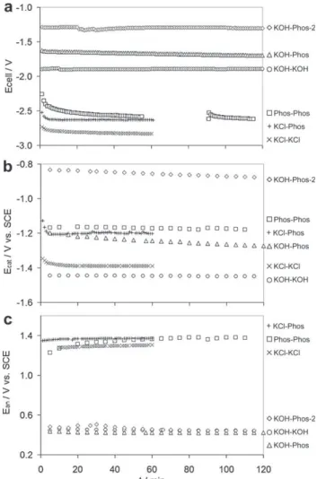
P ¼ 101.3 kPa) with a faradic efficiency of 92.1%.Fig. 6presents the cell voltage and the cathodic and anodic potentials measured during 2 h of continuous galvanostatic electrolysis for the conditions mentioned inTable 1. The experiments using KCL as anolyte (conditions ‘KCl-KCl’ and ‘KCl-Phos’) were kept operating for only 1 h. The lowest cell voltage was found when KOH 25%w was used as the anolyte and phosphate 1 M as the catholyte (condition ‘KOH-Phos-2’) with a stable value of 1.30 V, while the highest cell voltage was obtained when using a 0.1 M KCl solution in both the anodic and cathodic compart-ments (condition ‘KCl-KCl’), attaining 2.83 V (Fig. 6a).
The cathodic potential (Ecat) showed a strong dependency
on the electrolyte composition (Fig. 6b). The highest cathodic potential was found with KOH 25%, with a value of #1.45 V vs. SCE, which is not surprising when one considers the alkalinity of the solution, with pH near 15 (Table 2). A 0.1 M KCl solution also gave high cathodic potentials (#1.39 V vs. SCE) because of its lack of buffering capacity, which allowed the pH of the catholyte to increase from 5.5 to 11.9 (Table 2). When phos-phate 0.5 M was used (conditions ‘KCl-Phos’, ‘Phos-Phos’ and ‘KOH-Phos’) the cathodic potential was less negative, with values between #1.15 and #1.27 V vs. SCE. When the anolyte was KOH and the catholyte was 0.5 M phosphate (condition ‘KOH-Phos’), the cathodic potential decreased by 0.5 mV min#1due to a pH augmentation from pH 8.0 to 11.0.
This pH modification was probably caused by proton diffusion from the cathodic compartment to the anodic one because of the great pH difference between the two compartments of about 7 pH units. A similar phenomenon was observed when a higher concentration of phosphate was used in the cathodic compartment (condition ‘KOH-Phos-2’) but with a slightly smaller decrease of the potential with time (0.4 mV min#1)
even though the initial pH gradient was much higher with about 11 pH units of difference between the two compart-ments. This was due to the higher phosphate concentration, which increased the buffering capacity of the catholyte. In these last conditions (‘KOH-Phos-2’), the cathodic potential
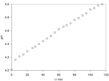
was the lowest and went from #0.83 to #0.88 V vs. SCE, thanks to a lower pH (between 4.0 and 5.0) and a higher phosphate concentration.
The anodic potential (Ean) curves were distributed in two
different zones (Fig. 6c): one with high anodic potentials, between 1.23 and 1.37 V vs. SCE, which corresponded to conditions where the anolyte was not a KOH solution (condi-tions ‘KCl-KCl’, ‘KCl-Phos’ and ‘Phos-Phos’), and the other with potentials between 0.4 and 0.5 V vs. SCE, which corres-ponded to the experiments done using KOH 25%w as anolyte (conditions ‘KOH-KOH’, ‘KOH-Phos’ and ‘KOH-Phos-2’). The low anodic potentials obtained with KOH 25%w were due to a high concentration of OH#, which implied a lower
equili-brium potential (Nernst potential) and a low overpotential. The ohmic drop, cathodic and anodic overpotentials, process efficiency, energy efficiency, and total energy
Table 1 e Conditions used for each experiment performed in galvanostatic mode. Condition name Anolyte Catholyte KCl-KCl KCl 0.1 M pH ¼ 5.5 KCl 0.1 M pH ¼ 5.5 KCl-Phos KCl 0.1 M pH ¼ 5.5 KH2PO40.5 M, KCl 0.1 M, initial pH adjusted to 8.0 with KOH Phos-Phos KH2PO40.5 M, initial pH adjusted to 8.0 with KOH KH2PO40.5 M, initial pH adjusted to 8.0 with KOH
KOH-KOH KOH 25%w pH ¼ 15.2 KOH 25%w pH ¼ 15.2 KOH-Phos KOH 25%w pH ¼ 14.7 KH2PO40.5 M, initial pH adjusted to 8.0 with KOH
KOH-Phos-2 KOH 25%w
pH ¼ 14.7
KH2PO41.0 M pH ¼ 4.0
Fig. 6 e Variation of cell voltage (Ecell), cathodic (Ecat) and
anodic (Ean) potentials during galvanostatic electrolysis at
L1.35 mA cmL2for different conditions. The lack of points inFig. 6a, for ‘KOH-Phos-2’ condition is due to a data storage failure. The perturbation observed at 90 min was caused by stopping and restarting the electrolysis. Points were lacking for the cell voltage only; the cathodic and anodic potentials were measured independently with a multimeter.
consumed after 55 min of electrolysis are reported inTable 3for each experimental condition carried out in galvanostatic mode. The ohmic drop due to the resistance of the solution and the membrane, calculated as Uohm¼Ecell#(Ecat#Ean), had the
lowest values for conditions using KOH 25%w as anolyte, with 10 mV when the catholyte was KOH (condition ‘KOH-KOH’) and a value close to zero when the catholyte was phosphate solution (condition ‘KOH-Phos’) (Table 3). The experiments carried out without KOH showed ohmic drops between 50 and 140 mV, which were 5e14 times larger than when using KOH. This can be explained by the difference of ionic concentration (then difference of conductivity) for the various solutions: concentration is almost 10 to 50 greater in KOH 25%w solution than in phosphate 0.5M or KCl 0.1 M ones, respectively.
The overpotentials were calculated as the difference between the equilibrium potential and the potential measured in galvanostatic mode. By considering the Nernst equation applied to the reduction of a weak acid (HB), the equilibrium potential is written: Eeq HB=H2¼E o HB=H2þ RT 2Fln ½HB'2 !B#"2 PH2 (8) where Eo HB=H2¼ RT FlnKdiss (9)
with Kdissas the dissociation constant of the acid.
Substituting (9) in (8): Eeq HB=H2¼ RT FlnKdissþ RT 2Fln ½HB'2 !B#"2 PH2 (10) At equilibrium (no net current flowing):
½HB' !B#" ¼ !Hþ" Kdiss (11) Substituting (11) in (10): Eeq HB=H2¼ RT 2Fln !Hþ"2 PH2 (12) The Nernst equation for the reduction of protons in solution is, logically, found again as HB acts as a homogeneous catalyst. Equations (8)e(12) show that the equilibrium or Nernst potential for a weak acid depends on the pH of the solution and is independent of the analytic concentration of the weak acid. The anodic pH was measured continuously while the cathodic pH was measured at the beginning and at the end of the experiments. The anodic Nernst or equilibrium potentials ðEeq
anÞwere calculated using the measured anodic pH values and the cathodic equilibrium potentials ðEeqcatÞwere calculated with estimated cathodic pH values. The cathodic pH was estimated by considering a linear variation between initial and final pH values. This hypothesis was based on the linear behaviour of the measured anodic pH when phosphate or KOH were used (Fig. 7) and was confirmed with the ‘KOH-Phos-2’ condition, an experiment where the cathodic pH was measured continuously (Fig. 8). For the experiment using KCl solution in the two compartments (condition ‘KCl-KCl’), the cathodic pH measured at the end of the experiment was the value used to calculate Eeqcat. The cathodic overpotential ðhcat¼Ecat#EeqcatÞ was about 0.5 V when the catholyte was a 0.5 M phosphate solution (conditions ‘KCl-Phos’, ‘Phos-Phos’ and ‘KOH-Phos’). With 1.0 M phosphate as the catholyte (condition ‘KOH-Phos-2’), the overpotential was 0.34 V. For this condition, the pH of the catholyte was between 4.0 and 5.0 and the species involved in the cathodic reaction was H2PO4#, present in 99% of the total
phosphate concentration, proving once more that the pre-sence of a protonated phosphate species had a catalytic effect on the cathodic current. A higher concentration of phosphate, for example 1.5 M at pH between 4 and 5, would certainly
Table 3 e Cell voltage (Ecell), ohmic drop (Uohm), cathodic (hcat) and anodic (han) overpotentials, energy efficiency, equilibrium
cell potential ðEeqcellÞ, process efficiency, and energy spent for each experimental condition after 55 min of electrolysis at 1.35 mA cmL2.
Condition Ecell(V) Uohm(V)
(Ecell#
(Ean#Ecat))
han(V)
ðEan#EthanÞ
hcat(V)
ðEcat#EthcatÞ
Energy eff. (%) (100 % 1.23/Ecell) Ecelleq(V) ðEeq an#E eq catÞ Process eff. (%) ð100 % Eeqcell=EcellÞ Spent energy (kWh/Nm3H 2)b KCl-KCl 2.8 0.14 0.43 #0.44 44 1.82 64 7.3 KCl-Phos 2.6 0.06 0.45 #0.48 47 1.63 62 6.8 Phos-Phos 2.6 0.05 0.85 #0.46 47 1.23 47 6.6 KOH-KOH 1.9 0.01 0.37 #0.31 65 1.21 64 4.9 KOH-Phos 1.7 0.00 0.30 #0.47 72 0.90 54 4.3 KOH-Phos-2 1.3 #0.01a 0.33a #0.34a 95 0.64 49 3.4
a These values are not exactly the real ones because the ohmic drop for condition ‘KOH-Phos-2’ was negative. The error can be attributed to a slight deviation of the reference electrodes.
b Energy spent per normal cubic meter of produced hydrogen at T ¼ 273.15 K, P ¼ 101.3 k.
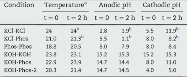
Table 2 e Initial (t [ 0) and final (t [ 2 h) values of pH and temperature of the cell.
Condition Temperaturea Anodic pH Cathodic pH
t ¼ 0 t ¼ 2 h t ¼ 0 t ¼ 2 h t ¼ 0 t ¼ 2 h KCl-KCl 24 24b 2.8 1.9b 5.5 11.9b KCl-Phos 21.0 21.3b 5.5 1.1b 8.0 8.2b Phos-Phos 18.8 20.5 8.0 7.9 8.0 8.4 KOH-KOH 23.8 23.1 15.2 15.3 15.2 15.3 KOH-Phos 22.9 23.9 14.7 14.4 8.0 11.0 KOH-Phos-2 20.3 21.4 14.7 14.5 4.0 5.0
a The temperature was measured on the anodic side. b t ¼ 1 h.
generate lower overpotentials. The cathodic overpotential found with the KOH catholyte, although similar to the value obtained in phosphate 1M catholyte (condition ‘KOH-Phos-2), was the lowest of the five experiments because the proton sources were the water molecules themselves. The large concentration of water molecules (about 56 M) at the surface of the electrode produced a high reaction rate.
The lowest anodic overpotentials ðhan¼Ean#EeqanÞ, with values between 0.37 and 0.31 V, were obtained using KOH 25% w as the anolyte because the large concentration of OH#
produced high reaction rates. The high anodic overpotential of 0.8 V found with phosphate 0.5 M as the anolyte (condition ‘Phos-Phos’), was probably caused by a poisoning of the plat-inum anode due to the adsorption of phosphate ions on its surface, as was seen to happen in the linear voltammetic study using platinum as the working electrode for the cathodic side (Fig. 3). Using another anode material may prevent anode poisoning and give lower overpotentials.
The energy efficiency (Eneff), calculated as the ratio
between the Gibbs free energy of hydrogen combustion (DGcomb¼ #237.2 kJ mol#1) and the Gibbs free energy of the
electrochemical process DGelec ¼ #2FEcell (equation (13))
ranged from 44% for the system with KCl solution as both electrolytes (condition ‘KCl-KCl’) to 94.6% when using KOH as anolyte and 1 M phosphate solution as catholyte (condition ‘KOH-Phos-2’) (Table 3). Eneff¼ #DG! comb DGelec $ %100 ¼ # 237:2 kJ=mol 2FEcell $ %100 ¼ #1:23 V Ecell $ %100 (13)
The energy efficiency of 94.6% obtained for this last case (condition ‘KOH-Phos-2’) is quite high if compared to the efficiencies found in industrial processes (70e79%)[2]. Further analysis showed that the high efficiency found for condition ‘KOH-Phos-2’ came from the low cell voltage obtained thanks to the pH difference between the compartments. To take the effect due to the pH of the solutions into account, the process efficiency was calculated as
Peff¼ # Eeq an#Eeqcat Ecell $ %100 (14)
which represents the percentage of the energy that was used to produce hydrogen and oxygen and was not lost in the form of anodic or cathodic overpotentials or ohmic drop. Its values were between 47 and 64% (Table 3). These values show that the performance of the reactor is not optimal, but it serves well enough for the purpose of this section, which is to eva-luate the use of phosphate solutions as catholytes and compare them with KOH and KCl solutions.
In industrial electrolysis, typical values for the energy consumption are between 4.5 and 5 kWh Nm#3H
2. The total
energy consumption found in the present work for each operating condition is listed inTable 3. The best values were found when using KOH as anolyte and KOH or phosphate solution as catholyte (conditions ‘KOH-KOH’, ‘KOH-Phos’, Phos-2’). For the alkaline electrolysis (condition ‘KOH-KOH’) and the electrolysis in the presence of 0.5 M phosphate (condition ‘KOH-Phos’), the energy consumption values were inside the range of those found in classical electrolysis. However, the system with 0.5M phosphate (‘KOH-Phos’) was better than alkaline electrolysis by 12%. When the concentra-tion of phosphate was higher (condiconcentra-tion ‘KOH-Phos-2’), the energy spent to produce 1 Nm3of hydrogen (T ¼ 273.15 K,
P ¼ 101.3 kPa) was 3.4 kWh Nm#3H
2, which is 31% less than the
energy required in the alkaline condition (‘KOH-KOH’). Although this energy gain was principally due to the pH difference between the compartments, the presence of phos-phate was necessary to maintain the pH difference and to allow low overpotentials. Nevertheless although a process with an acid catholyte and a basic anolyte would seem to give an energetic advantage over using a KOH solution in both compartments, such a process would need a constant feed of acid and alkaline solutions into the cathodic and anodic compartments respectively. The regeneration of the electro-lytes would also be necessary to avoid phosphate salt precipi-tation. Here the purpose of using a KOH solution as the anolyte was simply to focus on the performance of the cathodic side. It Fig. 7 e Measured pH values in the anodic compartment for
each condition during galvanostatic electrolysis at L1.35 mA cmL2.
Fig. 8 e Measured pH in cathodic compartment for condition ‘KOH-Phos-2’ during galvanostatic electrolysis at L1.35 mA cmL2.
was clearly shown that phosphate species have a real interest. This new technology, using a phosphate solution at mild pH as catholyte to produce hydrogen on stainless steel, may be an efficient cathodic system for the microbial electrolysis cells (MEC) where the oxidation of water is replaced by the oxidation of organic compounds catalysed by a microbial biofilm. Our recent results gave convincing proofs that the phosphate/ stainless steel system was successfully applied in a MEC pilot, ensuring high hydrogen production rates[19].
4.
Conclusions
A voltammetric study of the reduction of phosphate solutions was made on stainless steel 316L and platinum cathodes. The results confirm that phosphate species serve as a source of hydrogen atoms that need less energy than water for their reduction. This suggests that phosphate could be a promising homogeneous catalyst for the reduction of water to produce hydrogen. Stainless steel electrodes of type 316L show a stable behaviour when used as the cathode in the electrolysis of phosphate solutions.
Hydrogen was produced by the electrolysis of KCl, KOH and Phosphate solutions in a two compartment filter-press Plexi-glas reactor using a stainless steel 316L cathode and a platinum grid anode. Phosphate 1 M at pH between 4.0 and 5.0 as the catholyte can equal the performance (same cathodic over-potential) of a KOH 25%w solution but with the advantage of working at mild pH values. A more concentrated phosphate solution at the same pH values, without reaching the saturation concentration of about 1.6 M at 20!C[20], could give even better results by generating lower cathodic overpotentials. Working at mild pH values allows the use of low-cost construction mate-rials and reduces the maintenance cost by increasing the life-span of membranes, joints, pumps etc. The mild pH conditions and the homogeneous catalysis of phosphate permit the use of stainless steel electrodes instead of electrodes using catalysts such as nickel. Furthermore, the system stainless steel/phos-phate constitutes a very promising cathodic system for the microbial electrolysis cells that are now being developed[21].
The hydrogen production process presented here is the subject of an international patent[22]. Progress is being made to optimise the process, with a double purpose: to design a hydrogen production plant requiring less capital invest-ment, reaching lower maintenance costs than traditional electrolysis plants, and to develop efficient MECs.
Acknowledgements
This work was possible thanks to the financial support of CNRS and CEA-Saclay, France, and of CONACYT, Mexico.
r e f e r e n c e s
[1] Dunn S. Hydrogen futures: toward a sustainable energy system. Int J Hydrogen Energy 2002;27:235e64.
[2] Wendt H, Kreysa G. Ge´nie Electrochimique. Paris: DUNOD; 2001.
[3] Kibria MF, Mridha MS, Khan AH. Electrochemical studies of a nickel electrode for the hydrogen evolution reaction. Int J Hydrogen Energy 1995;20:435e40.
[4] Podesta JJ, Piatti RCV, Arvia AJ. The influence of iridium, ruthenium and palladium on the electrochemical behaviour of Co-P and Ni-Co-P base amorphous alloys for water electrolysis in KOH aqueous solutions. Int J Hydrogen Energy 1995;20:111e22.
[5] Marcelo D, Dell’Era A. Economical electrolyser solution. Int J Hydrogen Energy 2008;33:3041e4.
[6] Olivares-Ramı´rez JM, Campos-Cornelio ML, Uribe Godı´nez J, Borja-Arco E, Castellanos RH. Studies on the hydrogen evolution reaction on different stainless steels. Int J Hydrogen Energy 2007;32:3170e3.
[7] Albery WJ. Electrode kinetics. Oxford: Clarendon Press; 1975. [8] Daniele S, Lavagnini I, Baldo MA, Magno F. Steady state
voltammetry at microelectrodes for the hydrogen evolution from strong and weak acids under pseudo-first and second order kinetic conditions. J Electroanal Chem 1996;404:105e11. [9] Heyrovsky J, Kuta J. Principles of polarography. New York:
Academic Press; 1966.
[10] Da Silva S, Basse´guy R, Bergel A. Electrochemical
deprotonation of phosphate on stainless steel. Electrochim Acta 2004;49:4553e61.
[11] Marinovic V, Despic AR. Hydrogen evolution from solutions of citric acids. J Electroanal Chem 1997;431:127e32. [12] Marinovic V, Despic AR. Pyrophosphoric acid as a source of
hydrogen in cathodic hydrogen evolution on silver. Electrochim Acta 1999;44:4073e7.
[13] Stojek Z, Ciszkowska M, Osteryoung JG. Self-enhancement of voltammetric waves of weak acids in the absence of supporting electrolyte. Anal Chem 1994;66:1507e12. [14] O’NeiIl P, Busi F, Concialini V, Tubertini O. The use of
phosphate to generate H-atoms at pH 5-8 as determined by photocurrents: electrochemical properties of H-atoms. J Electroanal Chem 1990;284:59e65.
[15] Takehara K, Ide Y, Nakazato T, Yoza N. On the assignment of the redox peaks observed in phosphate and phosphite solutions at a Pt electrode. J Electroanal Chem 1990;293: 285e90.
[16] Molina A´, Morales I. Singularities of the catalytic mechanism in its route to the steady state. J Electroanal Chem 2005;583: 193e202.
[17] De Silva Mun˜oz L, Bergel A, Basse´guy R. Role of the reversible electrochemical deprotonation of phosphate species in anaerobic biocorrosion of steels. Corros Sci 2007;49: 3988e4004.
[18] Dissociation constants of inorganic species. In: Lide DR, editor. CRC handbook of chemistry and physics, Internet version 2007. Boca Raton, FL: Taylor and Francis; 2007. [19] De Silva Munoz L, Erable B, Etcheverry L, Riess J, Basse´guy R,
Bergel A. Combining phosphate species and stainless steel cathode to enhance hydrogen evolution in microbial electrolysis cell (MEC). Electrochem Commun 2010;12:183e6. [20] Aqueous solubility of inorganic compounds at various
temperatures. In: Lide DR, editor. CRC handbook of chemistry and physics, Internet version 2007. Boca Raton, FL: Taylor and Francis; 2007.
[21] Logan BE, Call D, Cheng S, Hamelers HVM, Sleutels T, Jeremiasse AW, et al. Microbial electrolysis cells for high yield hydrogen gas production from organic matter. Environ Sci Technol 2008;42:8630e40.
[22] Basse´guy R, Bergel A, Da Silva S, De Silva Mun˜oz L, Feron D, Roy M, deposited by CEA&INPT. Dispositif d’e´lectrolyse de l’eau et son utilisation pour produire de l’hydroge`ne. Water electrolysis device, France Patent FR 2 904 330, 2006, International Patent WO08012403, EP 2 047 011, AU 2007279151; 2009.