Effect of Temperature on the Relaxation of Polyvinyl
Chloride Flanges
by
Zijian ZHAO
THESIS PRESENTED TO ÉCOLE DE TECHNOLOGIE SUPÉRIEURE
IN PARTIAL FULFILLMENT FOR THE MASTER’S DEGREE WITH
THESIS IN AEROSPACE ENGINEERING
M.A.Sc.
MONTREAL, JUNE 05 2017
ÉCOLE DE TECHNOLOGIE SUPÉRIEURE
UNIVERSITÉ DU QUÉBEC
This Creative Commons licence allows readers to download this work and share it with others as long as the author is credited. The content of this work can’t be modified in any way or used commercially.
BOARD OF EXAMINERS THIS THESIS HAS BEEN EVALUATED BY THE FOLLOWING BOARD OF EXAMINERS
Mr. Hakim Bouzid, Thesis Supervisor
Département de génie mécanique at École de technologie supérieure
Mr. Anh Dung Ngô, President of the Board of Examiners
Département de génie mécanique at École de technologie supérieure
Mrs. Martine Dubé, Member of the jury Département de génie mécanique
THIS THESIS WAS PRENSENTED AND DEFENDED
IN THE PRESENCE OF A BOARD OF EXAMINERS AND PUBLIC MAY 28, 2017
ACKNOWLEDGMENT
I would like to thank my wife, Mingxia Wang, for her invaluable support during my studies. Without her contribution, there is no possible to finish my work.
I would like to thank my parents, give me immense support and motivation.
I would like to thank my director, Hakim A. Bouzid, for sharing his knowledge and experience without restriction. M. Bouzid has been a driving force and a great mentor from the beginning of this long quest.
I would like to thank my friends and colleagues, Aweimer, Xiaofan, Rahual, Long, Vafadar, for their friendship and advises.
Finally, I would like to thank the team of technicians, engineers and teachers at the Ecole de Technologie Superieure for their support in this project.
EFFET DE LA TEMPÉRATURE SUR LA RELAXATION DES BRIDES BOULONNÉES EN CHLORURE DE POLYVINYLE
Zijian ZHAO RÉSUMÉ
Après seulement un demi-siècle, le chlorure de polyvinyle (PVC) a remplacé presque toutes les applications des matériaux traditionnels, tels que l'argile, la fonte, l'acier et l'amiante-ciment pour devenir le premier matériau de tuyauterie. Le PVC est couramment utilisé dans le domaine de la corrosion et de la résistance biologique. Son installation et sa manipulation sont également deux facteurs contribuant à sa popularité.
Les systèmes de tuyauterie en PVC ont été largement utilisés pour le transport des fluides dans les sites industriels ainsi que pour la construction et le domaine domestique. Les assemblages à brides boulonnées sont des composants importants des systèmes de tuyauterie. Ils sont principalement utilisés comme une connexion démontable entre pression et intégrité structurelle et étanchéité. Pendant ce temps, la bride est un moyen recommandé de connecter deux équipements de matériaux différents.
En tant qu'autre matière plastique, PVC présente également du fluage dans le temps, dont la vitesse est influencée par la charge et la température. Les assemblages à brides boulonnées en chlorure de polyvinyle subissent une relaxation sous compression pour laquelle les propriétés de fluage sont différentes de celles sous tension. La performance d'étanchéité d'une connexion à bride est influencée par sa capacité à résister à la relaxation. Dans le but d'améliorer la capacité de charge et de réduire les pannes de fuites des assemblages à brides en PVC, il est important de bien comprendre et prévoir leur comportement de relaxation. Le premier objectif de ce travail est de développer un modèle de fluage du PVC basé sur des données de test de fluage obtenues à différentes charges de compression et à différentes températures. Le deuxième objectif est de simuler numériquement par la méthode des éléments finis la relaxation de la bride en PVC en utilisant le modèle de fluage développé à l'aide d'un assemblage de brides boulonnées NPS 3 classe 150 de matériaux différents, l'un en SA105 et l'autre en PVC. Cette étude présente les résultats d'un comportement de fluage-relaxation des brides en PVC dans diverses conditions de fonctionnement.
Mots Clés : fluage en compression, relaxation des brides boulonnées, fluage du PVC, distribution de température des brides
EFFECT OF TEMPERATURE ON THE RELAXATION OF POLYVINYL CHLORIDE FLANGES
Zijian ZHAO ABSTRACT
After a comparatively short half century, PolyVinyl Chloride (PVC) has invaded almost all applications of traditional materials, such as clay, cast iron, steel and asbestos cement, and becomes the premier pipe material. PVC is popular due to its advantages of immunity to corrosion and biological resistance. Convenient installation and handling are also two contributing factors to its popularity.
PVC Piping systems have been widely used for fluids conveyance in industrial and building sites and household. Bolted flange joints are important components of piping systems. They are mainly used as dismountable connections between pressure equipment ensuring structural integrity and leakage tightness. Meanwhile, the flange is a recommended mean to connect equipment of different materials.
As other plastic materials, PVC also experience creep over time, the rate of which is influenced by load and temperature. Polyvinyl Chloride bolted flange joints undergo relaxation under compression for which the creep properties are different from those under tension.
The sealing performance of a flange connection is impacted by its capacity to resist relaxation. For the purpose of improving the load currying capability and reduce leakage failures of PVC flange joints, it is important to properly understand and predict their creep-relaxation behavior.
The first objective of this work is to develop a PVC creep model based on creep test data obtained at various compressive loads and temperatures. The second objective is to simulate PVC flange relaxation using the developed creep model using a real NPS 3 class 150 bolted flange joint of dissimilar materials one made of SA105 and the other one of PVC materials. This study provides a fundamental understanding on how compression creep data obtained from the UGR fixture may be used to predict the short-term creep-relaxation behavior of PVC flanges under various operating conditions.
Keywords: Compression creep, relaxation of bolted flange, PVC creep model, Flange thermal distribution
TABLE OF CONTENTS
Page
INTRODUCTION ...1
CHAPITRE 1 LITERATURE REVIEW ...9
1.1 The History of PVC ...9
1.2 Types of PVC ...11
1.2.1 Unplasticized polyvinyl chloride (UPVC) ... 11
1.2.2 Cthlorinated polyvinyl chloride (CPVC) ... 12
1.2.3 Oriented polyvinyl chloride (OPVC) ... 12
1.3 PVC creep ...13
1.4 The Relaxation of Bolted Flange Joints ...15
1.5 Previous work on HOBT and UGR ...16
CHAPITRE 2 EXPERIMENTAL SET-UPS ...19
2.1 General ...19
2.2 Compression creep experiment fixture ...19
2.2.1 Overview of UGR assembly ... 19
2.2.2 Hydraulic system ... 21
2.2.3 Temperature measurement and control ... 22
2.2.4 Load measurement ... 24
2.2.5 Specimen strain measurement ... 24
2.3 Bolted flange joint experimental fixture ...25
2.3.1 Overview of the joint assembly ... 25
2.3.2 Temperature measurement and control ... 27
2.3.3 Deformation measurement ... 28
2.3.4 Bolt load measurement ... 31
2.3.5 The data acquisition system ... 31
2.3.6 Mounting specifications ... 32
2.3.7 Data recored system ... 32
2.4 Specimens ...33
2.4.1 Creep rings ... 33
2.4.2 PolyVinyle chloride flange ... 35
2.5 The experiment procedure ...38
2.5.1 The procedure of creep rings ... 38
2.5.2 The procedure of bolted joint relaxation experiment ... 39
CHAPITRE 3 FINITE ELEMENT MODELING ...43
3.1 Creep model ...43
3.1.1 Introduction ... 43
3.1.2 Creep model in ANSYS ... 44
3.1.3 Calculation of creep in ANSYS ... 45
3.2 Bolted flange joint model...46
3.2.1 Geometry model ... 47
3.2.2 Static model ... 48
3.2.3 CFD model ... 51
CHAPITRE 4 CREEP TEST RESULT ...57
4.1 General ...57
4.2 Test parameters ...57
4.3 Young’s modulus ...58
4.4 Thermal expansion coefficient ...58
4.5 Creep results...59
4.5.1 Creep data and curve fitting. ... 60
4.5.2 Creep strain ... 65
4.6 Identification the parameters ...67
4.6.1 Parameters interpolation ... 69
4.6.2 Creep parameters table ... 72
CHAPITRE 5 FLANGE TEST RESULTS AND DISCUSSION ...75
5.1 Introduction ...75
5.2 FEA results...75
5.2.1 Thermal loading ... 75
5.2.2 Heat convection and air flow surrounding the flange joint ... 76
5.2.3 Temperature distribution on the flange ... 76
5.2.4 Creep strain and bolt load relaxation ... 78
5.2.5 The axial displacement of the flange ... 81
5.3 Experimental results...81
5.3.1 Temperature measurements ... 81
5.3.2 Bolt load relaxation ... 82
5.3.3 The axial displacement of the flange due to rotation ... 83
5.4 Comparison of FEA and experimental results ...85
5.4.1 Temperature distributions ... 85
5.4.2 Blot load relaxation ... 86
5.4.3 Temperature bolt load sensitivity test ... 88
5.4.4 Bolt load fluctuation during heating phase ... 90
5.4.5 The axial displacement of the flange ... 91
CONCLUSION ...95
RECOMMENDATIONS AND FUTURE WORK ...97
LIST OF TABLES
Page
Table 2.1 Parameters and characteristics of the HOBT assembly ...32
Table 2.2 The groups of creep test ...39
Table 2.3 Recommended bolt torque ...40
Table 2.4 Bolt and washer ...41
Table 3.1 Bolt pre-tension ...50
Table 4.1 The temperatures and stress for creep tests...57
Table 4.2 Young's modulus ...58
Table 4.3 Thermal expansion coefficient ...59
Table 4.4 Goodness of fit for 140 °F ...62
Table 4.5 Goodness of fit for 113 °F ...64
Table 4.6 Goodness of fit for 83 °F ...65
Table 4.7 Curve fitting deviation ...69
Table 4.8 Creep parameters function table ...70
Table 4.9 Goodness of parameters interpolations ...72
Table 4.10 Creep parameters table ...73
Table 5.1 Temperatures in fixture ...81
LIST OF FIGURES
Page
Figure 0.1 PVC pipe system ...1
Figure 0.2 Standard Saddle Fusion Joint ...5
Figure 0.3 Bolted flange joint between PVC to ductile iron ...6
Figure 1.1 Effect of orientation on the polymeric structure ...13
Figure 1.2 PVC creep tensile test ...15
Figure 1.3 Old HOBT test rig (Bouzid, 2013) ...17
Figure 2.1 UGR fixture ...20
Figure 2.2 UGR UI 1 ...21
Figure 2.4 Cooling system on UGR ...22
Figure 2.5 Thermocouples on upper platen ...23
Figure 2.6 Thermocouples on the ring ...23
Figure 2.7 The load sensor of UGR ...24
Figure 2.8 LVDT on UGR fixture ...25
Figure 2.10 HOBT fixture ...26
Figure 2.11 Typical cross section of HOBT fixture ...27
Figure 2.12 HOBT strain gauges ...29
Figure 2.13 The LVDT positions on HOBT ...29
Figure 2.14 HOBT LVDT calibrator ...30
Figure 2.15 HOBT calibration factors ...30
Figure 2.16 The bolt-rod assembly ...31
Figure 2.17 The UI of HOBT LabVIEW ...33
Figure 2.19 PVC pipe ...34
Figure 2.20 Van Stone type flanges and Solid type ...35
Figure 2.21 Solid PVC flange ...36
Figure 2.22 The lower face of PVC flange ...36
Figure 2.23 The machined lower face of PVC flange ...37
Figure 2.24 LVDT screws on flange ...38
Figure 2.25 Tightening torque ...41
Figure 2.26 Torque sequence ...42
Figure 3.1 Creep strain due to constant applied stress ...43
Figure 3.2 The main fcators of PVC flange ...47
Figure 3.3 ¼ geometry model of the PVC bolted flange joint ...47
Figure 3.4 Expansion flange FEM model ...48
Figure 3.5 Expansion test assembly FEM model ...48
Figure 3.6 Symmetry surfaces of static model ...49
Figure 3.7 Bolt coordination ...50
Figure 3.8 Bolt load direction...50
Figure 3.9 Boundary condition for the static model ...51
Figure 3.10 CFD model ...52
Figure 3.11 Refined areas ...53
Figure 3.12 Fluid domains...54
Figure 3.13 The opening boundaries ...54
Figure 3.14 Symmetry planes in CFD model ...55
Figure 4.1 Thermal expansion ...59
XI
Figure 4.3 Fitted creep data at 140 °F ...62
Figure 4.4 Creep displacements at 113 °F ...63
Figure 4.5 Fitted creep data at 113 °F ...63
Figure 4.6 Creep displacements at 83 °F ...64
Figure 4.7 Fitted creep data at 83 °F ...65
Figure 4.8 Creep at 140 °F ...66
Figure 4.9 Creep at 113 °F ...66
Figure 4.10 Creep at 83 °F ...67
Figure 4.11 Curving fitting for creep data at 83 °F ...68
Figure 4.12 Curving fitting for creep data at 113 °F ...68
Figure 4.13 Curving fitting of creep data at 140 °F ...69
Figure 4.14 Parameters interpolation of f1(T) ...71
Figure 4.15 Parameters interpolation of f2(T) ...71
Figure 4.16 Parameters interpolation of f3(T) ...72
Figure 5.1 The air flow of environment ...76
Figure 5.2 Thermal distribution of the bolted flange ...77
Figure 5.3 Thermal distribution of the flange and tube ...78
Figure 5.4 Creep strain for the flange ...79
Figure 5.5 The simulation result for load relaxation with heat first ...80
Figure 5.6 The simulation result for load relaxation with tighten first ...80
Figure 5.7 The test load relaxation with heat first ...82
Figure 5.8 The test load relaxation with tighten first ...83
Figure 5.9 The LVDT data for the test with tighten first ...84
Figure 5.11 The relaxation of bolt load for first test ...86
Figure 5.12 The relaxation of bolt load for the second test ...87
Figure 5.13 HOBT sensitivity test ...88
Figure 5.14 Load sensitivity test ...89
Figure 5.15 The load and temperature change in heat phase ...90
Figure 5.16 The FEA and experiment displacement results of heat first ...91
Figure 5.17 The FEA and experiment displacement results for tightening ...91
LIST OF ABREVIATIONS
ASME American Society of Mechanical Engineers CFD Computational Fluid Dynamics
HOBT Hot Blowout Test
LVDT linear variable differential transformers PID Proportional Integral Derivative
PTFE Polytetrafluoroethylene UGR Universal Gasket Rig
PVC PolyVinyl Chloride
SSE Sum of Squared Error SST Sum of Squares Total
LIST OF SYMBOLS
cr
ε Change in equivalent creep strain with respect to time (mm/mm/s) cr
ε Equivalent creep strain (mm/mm) et
ε Equivalent total strain x ε Strain is x direction y ε Strain is y direction z ε Strain is z direction
σ
Equivalent stress (MPa)t Time (s)
T Temperature (K)
ID Inner diameter OD Outer diameter
INTRODUCTION
The features of PVC piping systems
The first PVC copolymer tubes were produced by 1932. Three years later, the first PVC pipes were produced by melting PVC powder on a roll mill and rolling the sheet produced up to a billet and then PVC pipes were made by a ram extruder in a discontinuously working process. However, this process was not suitable enough for PVC since it was used for celluloid which could cause the unreliable quality of related products.
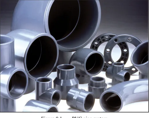
Figure 0.1 PVC pipe system Uni-Bell PVC Pipe Association (2011) .
Nevertheless, these early PVC pipes were suitable for drinking water supply piping and waste water piping because of their chemical resistance, odorless, tasteless and smooth interior surface. During 1936 to 1941, a number of PVC pipelines were laid in central cities
of Germany. As expected, those pipelines are still in use today without serious problems except few damages caused by bombing during World War II.
It was not until 1950 that PVC pipe experienced a drastic improvement and became widely used as the extrusion technology evolved. Several European and American companies recognized the potential of PVC pipes and pursued the formulation and processing technologies with prominent achievements in the development of stabilizers, lubricants, processing aids and processing machinery engineered particularly for PVC. During this period, PVC pipe became competitive with traditional products in various areas, such as water and gas distributions, sewer and drainage, electrical conduit, chemical processing and drain, waste and vent piping. With the development of PVC materials, current PVC pipes have been used in areas like compressed gas and oil systems. The following section discusses the major features of PVC piping systems.
Durability
PVC pipe is a durable material because of its resistance to corrosion, chemical rotting, fatigue, fracture, and earthquake. It is resistant to almost all types of corrosion which occur in underground piping systems because PVC does not conduct electricity nor support biological growth. PVC pipe cannot be damaged by corrosive waters or aggressive soils and this outstanding feature makes it the first material choice for severe chemical environment.
The relatively high strength of PVC materials another advantage for its resistance to fatigue. It can withstand the magnitude of pressure surges which allows PVC pipe operate at maximum pressure without failure.
PVC pipe is able to yield under loading without fracturing. Thus it is well suited for underground piping applications where road surfaces experience external large deformation under traffic. The PVC material elasticity is also an important feature which makes it well suited for applications where dynamic soil movement or vibration is anticipated.
3
Therefore PVC pipes are the preferred choice for various medium and long-term applications. Presently, PVC accounts for about 85% of piping systems in the building and construction area, and it is estimated that over 75% of PVC pipes have a working live from 40 years up to 100 years. In other applications like cable insulation and window profiles, the statistics are also encouraging. Over 60% of PVC pipes have in-service lives of over 40 years.(Americanplasticscouncil, 2005)
Cost effectiveness
Based on its exceptional physical and technical properties, PVC pipes have great cost-effective performance in terms of lower maintenance cost, cheaper transportation, and easy installation. The long lifespan of PVC pipes, as discussed above, is a distinct characteristic for reduced system operating cost. In addition, PVC pipes provide an outstanding weight advantage compared with other piping materials. The low weight of PVC piping means fewer people required for installation and reduced manual handling difficulties thus saves the cost of labor. Less weight also leads to cheaper transportation charges and enables more payloads to be loaded.
When designing piping systems, one of the major requirements is joint tightness. PVC pipes are available with various assembly type joints such as fusion joint, gasketed joint, deep insertion joint and solvent cement joint, which can provide a high leakage performance.. While fusion joints are self-restraining and can fully seal the pipeline avoiding costly thrust restraints or thrush blocks, bolted gasketed joint provide the possibility of de-assembly and still maintain joint integrity.
In addition to the low pressure losses the smooth wall surfaces of PVC pipes are able to reduce fluid friction and eliminate encrustation and tuberculation. The combined features of PVC pipes such as light weight, flexibility, and self-restrained joints enable cost-effective installation methods which cannot be applied to other piping materials. These installation
methods including horizontal directional drilling, sliplining, pipe bursting and submerged or floating pipe can greatly save time and cost on many installations. (Association, 2006)
Safety
The feature of safety includes two aspects: the safety of PVC materials and the safety in applications that use PVC piping systems.
Firstly, PVC is a non-toxic and safe material which is widely used in water distribution and medical applications. It meets the international standards for safety and health in products and applications. It is also a safe choice for ecologically sensitive environments which requires the most reliable pipe materials.
The study 'A discussion of some of the scientific issues concerning the use of PVC' (1) by the Commonwealth Scientific and Industrial Research Organization (CSIRO) in Australia concluded in 2000 that PVC in its building and construction applications has no more effect on the environment that its alternatives. " (PVCConstruct, 2008)
PVC fire resistance and ductility enhance the safety of related applications and products. PVC material is difficult to ignite and will stop burning in the absence of an external ignition source because of its self-extinguishing feature. The fire safety characteristic of PVC makes it a favorable choice material in the building because it tends to char rather than generate flaming droplets. Additionally, the acid emission when heated is irritating thus can alert people to run away from the fire.
Ductile materials like PVC can deform under intense pressure without fracture or ultimate failure. Therefore, PVC material used for water, natural gas and industrial piping systems can safely handle localized increased stress that is caused by external impinge on the PVC piping equipment outside surface. (Association, 2006)
5
PVC Pipe Joints
In order to join piping components, the most appropriate engineering design should consider the joint type, the joint efficiency and joint durability. The integrity and versatility of the joining techniques used for PVC pipe allow the designer to take advantage of the performance and benefits of PVC in a wide variety of applications.
Typical connection methods for PVC pipe system include General Provision, Fusion methods, Thermal Heat Fusion Methods, Electrofusion (EF), Mechanical Connections and Flanged Connections.
Figure 0.2 Standard Saddle Fusion Joint Plastic pipe institute (2012)
PVC flange joint
PVC piping system began to replace the old ductile iron piping in water and waste water infrastructures in urban renewal since the advantages of PVC have been discovered. According to Edmonton’s water-distribution utility, only 1% of annual water breaks related to PVC pipes in spite that fact that 45% of the city’s network is PVC.
In most cases, it is difficult to completely replace the old piping system at the same time, which means a joint has to be used to connect the old piping (which is normally ductile iron)
and the new PVC piping as shown in Figure 0.3. Compared with other joint types, the bolted flange joint is more convenient because it is easy to align and assemble.
Figure 0.3 Bolted flange joint between PVC to ductile iron Shutterstock (2016)
Problems
Because the properties of PVC and metal are quite different, it is more difficult to predict the behavior of a flange joint between these two materials. The flange rigidity of PVC to metal is higher than a joint between PVC, which tends to leak more easily caused creep relaxation.
PVC piping normally could work over 100 years (Plastic Pipes in Water and Waste Water), however, this amount of time decreased significantly when the operational temperature is increased. In practical applications, the service period will be much less when PVC piping is utilized for a hot water (140F) supply system. Therefore, investigating the behavior of PVC under various temperatures will be helpful to determine the working condition of PVC piping and to create a related maintenance plan.
7
Research methodology
The service period of PVC piping systems is significantly reduced in high-temperature environments, mainly due to the creep relaxation. It greatly increases with temperature rising. Therefore, accurate simulation of creep behavior is very important in the prediction of leakage for PVC flange joints due to creep relaxation and to determine the flange operating conditions.
The appropriate PVC creep data and a suitable creep model are essential for creep simulation. In order to obtain the compression creep data, several PVC rings directly cut from PVC pipes were tested on the UGR at various compressive loads and temperatures. Since PVC creep strain is very sensitive to temperature (creep strain at 140 F is almost 10 times higher than the strain at 80 F in creep tests), the existing time hardening creep model cannot accurately predict the creep behavior under various temperatures. Thus, a modified time hardening creep model with functional parameters was built in this study.
Furthermore, two bolted flange relaxation tests were conducted using the Hot Blowout test (HOBT). These experiments use Van Stone type NPS 3 class 150 bolted PVC flanges. Results from these experiments are compared with the results obtained from a finite element analysis, which used the creep model with the functional parameters mentioned above to evaluate the new creep model.
Thesis content
This dissertation is divided into five chapters. The first chapter presents a literature review of PVC and the previous studies on HOBT and UGR and especially emphasizes the creep of PVC. The relaxation of bolted flange joints is also described.
The second chapter is devoted to introding UGR and the HOBT used in this study, including temperature, load and deformation measurement systems. It also includes a description of the specimens used in these two fixtures and the experiment procedures.
The third chapter presents the FE models used in static and CFD analysis and gives a detailed description of the creep model applied in finite element analysis.
The fourth chapter is divided into two parts. The first section deals with the material properties, including thermal expansion and young’s modulus. The second part focuses on analyzing creep test results and determining the creep model parameters.
The fifth chapter highlights the flange creep relaxation test results obtained by HOBT assembly, as well as the simulation result from FEA, to emphasize how the creep contributed to the relaxation of bolted flange joint. In the discussion part, except the relaxation of bolt load, it also presents flange deformation obtained from the tests and discusses the sensitivity of HOBT fixture.
CHAPITRE 1 LITERATURE REVIEW 1.1 The History of PVC
In 1912, a German chemist, Fritz Klatte, discovered the easiest method for PVC industrial production, which is of great significance in the history of PVC industry. However, before him, there are few scientists who contributed to the development of PVC that are worth of mention.
In 1835, Henry Victor Regnault, a French scientist explained the existence of the monomer called vinyl chloride. In 1842, Eugen Baumann, a German chemist determined the density and the basic structural formula of PVC resin. He started a detailed research on this material and investigated the result of sunlight exposure of vinyl chloride in 1872 (Americanplasticscouncil, 2005, May). Fritz Klatte’s production method, which is based on the reaction of acetylene and the catalyst at elevated temperature in the presence of hydrogen, was allowed to lapse and the first industrial production commenced in the late 1920s in the USA. In 1931, PVC resin production plant was built in Germany which marked the breakthrough of PVC commercial production.
During the 100 years of discovery of PVC resin, this material was just treated as art treasures. The turning point was the appearance of vinyl chloride/vinyl acetate copolymer and the plasticized PVC resin, which provides a processable material at an appropriate melting temperature into a product that is permanently soft and flexible.
In 1928, Union Carbide, an American chemical company, improved the PVC material to make it easily processed for use in lacquers and hard molded articles. In 1932, US Goodrich Corporation discovered that plasticized PVC resin has soft and flexible characteristics and is resistant to corrosion under acid and alkaline solutions.
In 1937, The British ICI Company replaced rubber by plasticized PVC substance as layers for wire insulation. At this time, PVC as an effective macromolecular material was put into mass production.
The early stage of PVC resin manufacturing process is emulsion polymerization and solution polymerization, and the primary purpose is to replace the production of rubber coating, packaging containers, and other flexible materials.
However, the poor performance of emulsion resin and its high level of impurity content and production costs limit its application. In 1941 BF Goodrich produced PVC resin by suspension polymerization which presented better quality than the emulsion polymerization method especially in the aspects of electrical insulation, mechanical strength, and corrosion resistant. Additionally, the suspension polymerization method needs fewer auxiliaries and operates simpler than emulsion polymerization thus was rapidly adopted around the world.
This alternative manufacturing method of PVC resin has been further improved especially on the later treatment procedure of polymerization such as drying, packaging, dust reduction and obturated storage and transportation, which greatly promoted PVC resin production in the 1950s.
In the 1970s, environmental pollution and waste management became a serious problem, which affected the rapid economic growth of the 1960s. In PVC industry, mercury pollution was the main environmental issue, while the carcinogen of VCM as a severe problem which almost threatened the PVC industry. Therefore, many countries established regulations to limit VCM content in PVC production areas, and PVC manufacturers invested heavily in improving manufacturing environment. Although the toxicity of VCM reduced the PVC production and increased the manufacturing cost during that period, technological progress of PVC industry has also promoted and these techniques like the PVC suspension polymerization and continuous emulsion polymerization method have been still applied at present.
11
Due to its resistance to light, chemicals, and corrosion, PVC products presented an excellent performance for building applications thus became essential to the construction industry. The low cost, excellent durability and processability of PVC also make it the better option of materials for various industries such as healthcare, IT, transport and textiles. Currently, PVC is the third largest commodity plastic in the world after polyethylene and polypropylene.
1.2 Types of PVC
Polyvinyl chloride consists of PVC resin compounded with different proportions of stabilizers, lubricants, fillers, pigments, plasticizers and processing aids. Various types of PVC can be obtained from varying compounds of these ingredients to develop specific groups to meet the needs of various applications. However, the main part of each compound is PVC resin.
This chapter will introduce three major PVC types which are widely used in different areas: unplasticized polyvinyl chloride (UPVC), chlorinated polyvinyl chloride (CPVC) and oriented polyvinyl chloride (OPVC).
1.2.1 Unplasticized polyvinyl chloride (UPVC)
The unplasticized polyvinyl chloride (UPVC) compounds have the greatest short-term and long-term strengths, contain no plasticizers and include minimum compounding ingredients. As a low maintenance material, UPVC is extensively used for general purpose in building and construction industry. It is also used in products such as window frames, bottles, food packs, pipes, and pipe fittings. UPVC is rigid and hard in nature with an ultimate tensile strength of approximately 52 MPa at 20°C and can resist corrosion of most chemicals. Generally, unplasticized polyvinyl chloride can be used at temperatures up to 60°C, although the actual temperature limit depends on stress and environmental conditions.
1.2.2 Cthlorinated polyvinyl chloride (CPVC)
Chlorinated polyvinyl chloride (CPVC) is a high-performance thermoplastic produced by chlorination of polyvinyl chloride (PVC) resin with an increase in the chlorine content. Most of the features of CPVC are similar to PVC such as its resistance to fire because of its excellent corrosion resistance at a higher temperature. It is especially difficult to ignite and self-extinguish without being directly applied flame.
In addition to the shared features with standard PVC, as the chlorine content is increased the CPVC glass transition temperature increases significantly, which makes the service temperature of CPVC higher than standard PVC. Additionally, the mechanical properties of CPVC are more ductile which allows more flexure and crush resistance than PVC.
These characteristics of CPVC contribute to its wide range of popular applications in daily life, for example, the hot and cold water piping systems used for residential as well as construction purposes.
1.2.3 Oriented polyvinyl chloride (OPVC)
Oriented polyvinyl chloride (OPVC) is manufactured by a process giving the preferential orientation of long chain PVC molecules in the hoop or circumferential direction for pipes show as Figure 1.1. This greatly enhances the physical and mechanical properties in the hoop direction of PVC and provides OPVC a number of exceptional features without affecting the advantages of the original PVC. The ultimate tensile strength of oriented polyvinyl chloride (OPVC) could be twice that of the unplasticized polyvinyl chloride (UPVC). Those features give the products excellent qualities in terms of flexibility, resistance to fatigue and traction. The stretching process realigns the long PVC molecular chains and allows producing lighter products with a relatively thin wall while providing greater ductility, strength and impact resistance than standard PVC. In applications like pressure piping which present well-defined stress directionality, significant savings in materials and gains in strength can be obtained.
13
Figure 1.1 Effect of orientation on the polymeric structure (Vinidex, 2016)
1.3 PVC creep
The creep behavior of PVC material has raised attention since early times. For example in 1950s Faupel has studied PVC pipe creep and stress rupture behaviors under different conditions of static stress and time (Faupel, 1958). Niklas, H. and Eifflaender, K. tested the long-term behavior of PVC and polyethylene pipes loaded with liquid under pressure at various temperatures (Niklas et Eifflaender, 1959).
After decades, PVC creep started to be measured at high temperatures close to the glass region (Bergen, 1967). In most engineering applications, Poisson ratio of common structural material is considered as a constant in any deformation analysis. This is the case for most constitutive equations used to describe deformation behavior of solid bodies under loading. However, the dependence of Poisson ratio on time and strain should be considered when dealing with viscoelastic material such as PVC (Bertilsson et al., 1993; Ladizesky et Ward, 1971).
The creep phenomena of PVC is much more complex than metal because the volume does not change in most creep phenomena for metal. Several studies show that there is a volume change observed during short-term uniaxial creep tests under tension of PVC and other polymer materials (Bertilsson et al., 1993; Pampillo et Davis, 1971; Pixa, Le Dû et Wippler, 1988). The time-dependent variation of the volume used in these research studies cannot be described by a simple model because the strain and the deformation ratio are not proportional to each other. Although a relatively large number of experiments were conducted through the
years (Mallon, McCammond et Benham, 1972; Shamov, 1965; Theocaris, 1979), appropriate analytical methods for describing these phenomena have yet to be developed.
With the development of related research, the temperature has been considered as a variation in both short-term and long-term creep model (Read, Dean et Tomlins, 1994). Besides, the stress relaxation below glass transition temperature has also been investigated under the extension, and the data are obtained from a fixed deformation specimen and fitted with a normal log distribution function (Povolo, Schwartz et Hermida, 1996).
As computer technology evolved, finite element Method (FEM) became the tool of choice for the analysis of PVC products (Pantelelis et Kanarachos, 1998; Veronda et Weingarten, 1975). The early creep models used by FE softwares were not appropriate because they were not representative of the real behavior (Sakaguchi et Kaiga, 1986). In addition, most of the cases studied at the time were run under constant conditions of load and temperature leading to limited case analysis. Along with the wide use of polymer products, an increasing number of creep related studies were conducted (Dropik, Johnson et Roth, 2002; Sabuncuoglu, Acar et Silberschmidt, 2011). However, these studies mainly focused on polypropylene and other materials, while limited research was done on PVC. Most of the research work conducted on creep behavior was conducted on the short-term effect limiting the analysis to the primary creep phase, while the long-term behavior was neglected. The creep model calculated by Dropik et al.(2002) is shown as Eq.(0.1), the units of time and stress in this equation are minutes and psi, and the creep data is obtained from tensile test which is shown in Figure 1.2.
7 1.566 0.1736 1.066
cr e t
15
Figure 1.2 PVC creep tensile test Dropik et al. (2002)
Creep and relaxation have been studied by Barbero et Ford applying the equivalent time and temperature method (ETT) (Barbero et Ford, 2004) to analyze the polymer aging problem. Recently, with the development of rate-dependent plastic modeling, researchers started to simulate and predict the relaxation due to creep of plastic materials based on tensile tests. Acceptable prediction of creep failure of PVC pipes under internal pressure was achieved (Laiarinandrasana et al., 2011). Other applications such as wood/PVC composite has also been investigated, and the basic Norton creep model shown as Eq.(0.2) has been used in the research without considering the temperature effect (Pulngern et al., 2013). The units of time and force in this equation are hours and KN.
8 0.9197 0.222 3.8797
cr e t
ε = −σ (0.2)
1.4 The Relaxation of Bolted Flange Joints
The literature on PVC piping systems focusses mainly on pipes subjected to internal pressure (Faupel, 1958; Mao et al., 2011; Scavuzzo et Srivatsan, 2006). External forces such as
bending moments were also considered because they were major contributing factor to failure. Wham et al (2016) conducted experiments on a PVCO pipeline with bell-and-spigot joint buried under the ground subjected to a simulated earthquake load. It showed that the PVCO pipeline has a good capacity to accommodate horizontal ground strain (Wham et al., 2016).
The relaxation of bolted flange gasketed joints essentially results from the creep of gasket (Bouzid et Chaaban, 1997). However, the contribution of flange can also be significant particularly if it is made of PVC or similar materials. The rigidity of bolted joint greatly affects the level of relaxation (Nassar, 2009). The relaxation of the bolt load is due to creep of metallic flanges has also been researched with numerical method and finite element method (Nechache et Bouzid, 2008). However, there are no available studies on PVC flange creep.
1.5 Previous work on HOBT and UGR
The two fixtures used in this study, UGR and HOBT, have been utilized by previous researchers in the Static and Dynamic Sealing Laboratory of the École de Technologie Supérieure.
The UGR is used to determine the mechanical and leakage performance of gasketing products. It is also used to obtain the thermal expansion coefficient and creep properties under compression (Benabdallah, 2013). Two different gasses (helium and nitrogen) were used in the study by Grine et Bouzid (2013), and the range of measured leak rate was 1 to 0.0001 mg/s. The load was recorded to calculate the relationship between the gasket stress and leakage. The behavior of polytetrafluoroethylene (PTFE) at high temperature including creep was conducted on the UGR (Bouzid et Benabdallah, 2015). An additional fined tube and cooling fan were recently installed on the URG to accommodate the hydraulic system and instrumentation for higher temperature testing.
17
The HOBT fixture is designed to test the capacity of PTFE based gasket to resist creep and hot blowout (Bouzid et al., 2001). It is used to determine the maximum safe operating temperature of PTFE-based gaskets. Recently PTFE gaskets were tested in this fixture to investigate the effects of thermal cycles and other effects such as Creep and thermal Ratcheting. The result can be used to predict the short and long term performance gaskets at high temperature (Bouzid et Benabdallah, 2015b). The short-term thermal relaxation resistance is investigated in this HOBT fixture to determine the margin of safety against an in-service blowout under thermal cycling. The recommended service temperature for PTFE-based gaskets is still subjected to research using also the UGR fixture (Rahul et al.). The result shows that the UGR and HOBT are excellent experimental test fixtures to investigate the short and long term behavior of PTFE gaskets for high-temperature service.
CHAPITRE 2
EXPERIMENTAL SET-UPS 2.1 General
The UGR and the HOBT are the two experimental test fixtures used in this study. The UGR is used to test PVC rings under load with special focus on creep behavior to obtain the fundamental PVC creep mathematical model under compression. The relaxation tests of PVC flanges are conducted on the HOBT fixture. The results are compared with those obtained from FE analysis to validate the accuracy of the creep mathematical model.
2.2 Compression creep experiment fixture 2.2.1 Overview of UGR assembly
The experimental setup utilized for the compression creep tests is known as the UGR which is shown in Figure 2.1. The rig consists of two platens with a smooth surface finish of 0.6 μm. The rig can accommodate circular test samples with diameters rings ranging between 50 mm and 100 mm and a thickness of up to 9.5 mm. It can be used for the test with the purpose of measuring liquid and gas leak (Grine et Bouzid, 2013).
Figure 2.1 UGR fixture
The pressurization system has a gas bottle and a regulator. A pressure transducer and dial gauge are used in conjunction with an HP data acquisition. When the liquid is involved in the test, a cylinder is utilized for separating the gas and liquid to avoid the miscibility of fluids.
A special program is developed under LabVIEW to control the test rig monitor the test parameters such as load, temperature, pressure, time and leak rate using a data acquisition and control HP unit. The heating, pressurization and leak detection systems are also controlled by this program (Figure 2.2).
21
Figure 2.2 UGR UI 1
2.2.2 Hydraulic system
The compressive load is applied through hydraulic circuit, which consists of a hydraulic pump, an accumulator, and a hydraulic tensioner. There are two hydraulic valves and two oil pressure gages installed in the hydraulic system. A valve and a pressure gage are placed near the hydraulic pump, and another two are located near the hydraulic accumulator. The two hydraulic valves are closed after the load is applied to prevent a potential oil returning to the tank. The accumulator allows to maintain the load in case of a small leak in the system.
In order to avoid heat transfer to the hydraulic system and instrumentation the finned tube and cooling fan are installed to the UGR as shown in Figure 2.3. This cooling system allows higher material samples heating temperatures. Such a cooling system protects the hydraulic system and allows testing up to 300 Celsius degrees.
Figure 2.3 Cooling system on UGR
2.2.3 Temperature measurement and control
The temperatures at four different locations of the fixture are measured using K-type thermocouples. The positions of the thermocouples are located as indicated inFigure 2.4. The first thermocouple is installed on the top surface of the upper platen and is connected to the heater PID controller unit. The PID temperature controller adjusts the heat rate according to the temperature reading from this thermocouple.
The second thermocouple is also placed inside the upper platen, thus close to the test specimen, and is assumed as the target temperature of this fixture. Two other thermocouples are placed opposite to each other with one placed at the internal diameter and the other one at the outside diameter of the test ring specimen as shown in Figure 2.5. The average value of the two thermocouple readings is assumed to be the temperature of the specimen.
23
Temperature readings are recorded through a Labview data acquisition program every minute. Nevertheless the temperature reading is displayed on the screen every 10 seconds.
Figure 2.4 Thermocouples on upper platen
2.2.4 Load measurement
Figure 2.6 The load sensor of UGR
A full wheatstone bridge strain gage acting as a load cell is bonded to the bolt surface as shown in Figure 2.6 and the load cell is thermally compensated.
2.2.5 Specimen strain measurement
The displacement due to the compression of the specimen is measured using a linear variable differential transformer module (LVDT) installed on the side of the rig to pick up the relative movement between the upper and lower platens as shown in Figure 2.7. The LVDT is calibrated using the calibration micrometer. The displacement over thickness is transformed to the creep strain .
To avoid heat transfer from the platens to the LVDT through the supports an air duct brings air from a fan as shown in Figure 2.7. In addition the LVDT is thermally compensated and hence the impact of heat on the instrumentation is reduced to a minimum.
25
Figure 2.7 LVDT on UGR fixture
2.3 Bolted flange joint experimental fixture 2.3.1 Overview of the joint assembly
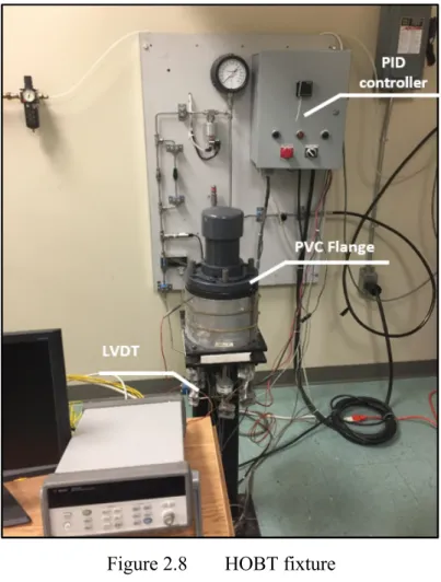
The HOBT fixture shown in Figure 2.8 is developed by the Static and Dynamic Sealing Laboratory of ETS. The main purpose of the HOBT fixture is to determine the maximum safe operating temperature of PTFE-based gaskets in order to avoid excessive compression that causes their blow-out. Due to the capacity of the test rig to measure relaxation of the bolt, it was found suitable for use to conduct PVC flange relaxation tests.
The HOBT fixture consists of a NPS 3 Class 150 slip-on bolted flanged joint and is adopted for the relaxation tests on the PVC flange of the same dimensions. This size and class joint is believed to be critical because of its relatively weak bolting and high failure rate experienced in the refinery and chemical plant piping systems (Bouzid et al., 2001). The PVC flange relaxation tests are useful to validate the suitability of the developed creep model obtained from creep data on ring specimens subjected to compression and used in conjunction with FEM.
The upper metallic flange was replaced with a PVC flange of the same size and class. The objective of the tests was to measure the effect of creep on the relaxation of the PVC flange. Therefore, no gasket was used in the joint and the results were compared with the predicted FE model, which uses the creep model obtained from the creep test.
Figure 2.8 HOBT fixture
Pressure can be applied inside of the HOBT fixture to simulate the internal pressure conditions of gas or liquid. The bolted flange assembly shown in Figure 2.9 consists of two distinct parts. The lower part, which consists of a base and a flange, is welded to a solid metal core. A cartridge heater that can generate up to 2,000 W is inserted into the metal core. The upper section features a tube of 0.08 meters in diameter that is welded to a removable
27
flange of the same type as the lower flange. The components that make up the assembly are made of SA 105 forged steel.
The central core and the upper section compose the pressurization chamber. Note that the internal volume of the tank, which is composed of the two flanges, is reduced to minimize high-energy releases from compressed gas escaping when a gasket bursts.
Figure 2.9 Typical cross section of HOBT fixture (Bouzid, 2015)
2.3.2 Temperature measurement and control
The entire fixture is heated from the inner shaft by a cartridge heater that is placed within the shaft. The temperature is controlled by a proportional integral derivative (PID) controller
which is connected to an internal thermocouple.A thermocouple is installed on one of the bolts to measure the temperature lag between the flanges and bolts.
There is a hole drilled on the lower flange so that the thermocouple can be inserted into it to obtain the inner temperature of the flange. The end of this hole is closed to the contact face and therefore, the temperate acquired by this thermocouple is assumed as the contact temperature.
There are a total of four thermocouples installed in the fixture. A removable thermal enclosure is used to thermally insulate the fixture to reduce heat loss and accelerate the heating process. This enclosure also provides a uniform thermal distribution to the flange.
2.3.3 Deformation measurement
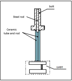
Two LVDTs used to measure the displacement of the flange. They are located in opposite positions between the bolts shown in Figure 2.11.As shown in Figure 2.10, these LVDTs are made of ceramic rods and calibrated by extensometers. The LVDTs provide a direct and instantaneous measurement of the deformation of the bolted flange joint. Therefore, the creep and rigidity of the flange joint can be evaluated through this measurement.
29
Figure 2.10 HOBT strain gauges
The two displacement sensors in the HOBT rig have been calibrated with the calibrator shown in Figure 2.12 and the displacement calibration factors are shown in Figure 2.13.
Figure 2.12 HOBT LVDT calibrator
31
2.3.4 Bolt load measurement
Four UNB 5 / 8-18 (in) ASTM A193 bolts are specially machined to be attached to the lower flange, which allow the seal between the lower and upper mounting flanges to be tightened. Each bolt is drilled in the center so that a rod of the same material can be inserted and welded at one end in order to measure the elongation and load. Figure 2.14 shows the bolt-rod assembly, which is connected to an extensometer using a ceramic rod inserted into a tube of the same material. The tension applied on the bolt during tightening causes a relative elongation between the bolt and the rod, which is measured by the extensometer making it possible to deduce the tension on the bolts.
Figure 2.14 The bolt-rod assembly (Bouzid, 2015)
2.3.5 The data acquisition system
The data acquisition system is developed to meet the needs of this study. Communication between the Agilent 34970a data acquisition and control system, and a computer running a LabVIEW interface enable the recording of data from the various sensors.
2.3.6 Mounting specifications
The table below summarizes the parameters that are taken into consideration when carrying out the HOBT assembly, as well as the technical characteristics of the various elements used.
Table 2.1 Parameters and characteristics of the HOBT assembly
Parameters Settings Features
Flange ANSI B16,5 to be welded and welded NPS 3 class Measuring the load on the Bolt Extensometer with strain gauge
Bolt type 4 bolts UNC 5 / 8-18 (in)
Maximum load 267 KN
Maximum temperature 400 ° C
Maximum Internal gas pressure 7.3 MPa
Heating Capacity 2 000 W
Heating rate 1 ° C / min
2.3.7 Data recored system
The HOBT workbench is equipped with necessary devices that are connected to a control data acquisition system and a LabVIEW program. These were developed and updated in previous research tests to monitor experiment parameters and control the pressure and heating systems. The HOBT program UI shown in Figure 2.15.
33
Figure 2.15 The UI of HOBT LabVIEW
2.4 Specimens 2.4.1 Creep rings
The PVC ring samples utilized in the creep test shown in Figure 2.16 are sliced from a 3 inch schedule 80 PVC pipe shown in Figure 2.17. The Vertical Machining Center (VMC) is used for the cutting process and the nominal width of the rings is 12mm. The maximum average width deviation of the ring specimens used in the tests is less than + 0.1 mm.
Figure 2.16 PVC rings
35
2.4.2 PolyVinyle chloride flange
Types of PVC flange
There are two types of PVC flanges, Van Stone style and solid type, which can be found on the market. Different to the one piece solid flange, the Van Stone style flange consists of two pieces, as shown in Figure 2.18. Compared with the solid type flange, which has a hub that is either socketed or threaded and that is attached to the pipe, the Van Stone style flange is easier to align as it has an independent flange that rotates around the hub. However, the Van stone style flange is normally less rigid than a solid flange under the same conditions.
Figure 2.18 Van Stone type flanges and Solid type (VinideX, 2014)
The common gaskets that are installed in bolted flange joints can exhibit creep based on its properties, as is the case with PTFE. Such creep also contributes to the relaxation of a flange joint. The focus of this study is the relaxation of the flange due to creep rather than to the gasket. As such, no gaskets are used in the experiment.
The solid 3 inch schedule 80 PVC slip-on flanges, are used in the experiment and are manufactured for use in thermoplastic piping systems (IPEX, 2016). They also feature webbing reinforcement on the top, as shown in Figure 2.19.
Figure 2.19 Solid PVC flange
Re-machined PVC flange
Normally, a gasket should be placed in the bolted flange joint between the PVC flange and metal flange to prevent leakage. In order to improve the contact pressure and increase the sealing capability between flanges and the gasket, there is a raised face to limit the contact surface of PVC flange with the gasket, as shown in Figure 2.20.
37
The raised face has concentric serrations to increase contact stress locally and therefore reduce leakage. Nevertheless, these serrations were machined off as no gasket is used in the experiment to avoid local stresses that could alter the flange creep test simulation. The raised face has been machined to a lower thickness to provide a better contact surface and to prevent stress concentration, as shown in Figure 2.21. The height of contact of the raised circle is machined to 1 mm.
Figure 2.21 The machined lower face of PVC flange
LVDT bolt screws
There are two bolt screws installed on the lower flange, illustrated in the left section of Figure 2.22, to make contact with the LVDT sensors. They provide the flange with displacement in the vertical direction. This feature has been updated for the second test, as can be seen on the right part of Figure 2.22, because the first set of bolts were pushed into the flange during the test. Therefore, two nuts are installed on the screws and glued into place to prevent relative movement.
Figure 2.22 LVDT screws on flange
2.5 The experiment procedure 2.5.1 The procedure of creep rings
The thermal load is applied first in this test, and this process takes a total 20 hours to reach and maintain the target temperature. The heat rate is controlled by a UGR experiment program coded with LabVIEW 8.6. This program has been verified and applied in previous experiments (Bouzid et Benabdallah, 2015a; Grine et Bouzid, 2013). When the entire system is heated to the experiment temperature, at 2 °F per minute, and stable at this temperature, the compression load is manually applied to the PVC rings by a hydraulic pressure pump. This loading process is applied at the same rate in all tests. Normally, the loading time is limited to 10 mins.
The creep test is conducted over five days (around 96 hours) after the load is applied. Once the whole system has cooled down to the ambient temperature (around 23℃), the load is released.
The UGR fixture is reset before applying the load in each test, and the hydraulic tensioner is manually pushed back to its initial position.
39
Experimental sets
There are three different stress levels applied to the ring sample at three selected temperatures, making for a total of nine tests. The test temperature is constant for each compressive stress.
Table 2.2 shows the details of the experiment groups and test sets.
Table 2.2 The groups of creep test
NO. Group Temperature (°F) Compression stress (MPa)
1 83 (28℃) 10 20 30
2 113 (45℃) 10 20 30
2 140 (60℃) 10 20 30
The lowest temperature during the creep test is 83 °F (28℃) because the ambient temperature in the lab is affected by central air-conditioning. This means that the room temperature is reduced during the evening and weekend. This can have a significant impact as PVC creep rate which is susceptible to temperature and thus these temperature variations can affect the results of the creep test. Therefore, a relatively higher temperature is selected as the lowest test temperature, which is maintained with a small variation range by the UGR thermal control system.
2.5.2 The procedure of bolted joint relaxation experiment
General
Two flange test experiments were conducted on the HOBT fixture. In the first test, the whole fixture is heated first after the flange joint is tightened. When the temperature has stabilized an more 20 hours have passed, the initial bolt load is applied according to the instructions of
the PVC pipe system installation manual (SPEARS, 2014). The effects of thermal expansion can be ignored in this procedure because the creep is the major concern for this test.
In the second test, the bolts are first tightened, as per the method in the first experiment, and then the whole assembly is heated. During the tests, measurements of temperature, bolt load displacement, and time are displayed on the LabVIEW interface every 10 seconds and recorded at a regular time interval of 1 minute.
Bolt load
The bolt load applied on the PVC flange is based on the recommended torque specified in the Schedule 80 PVC pipe flange manual of the flange supplier. The recommend bolt torques in the manual are showed in Table 2.3, because unnecessary over-torque will damage the PVC flange.
Table 2.3 Recommended bolt torque
Take from PVC technical manual, page 441 (SPEARS, 2015) Flange Size (in.) Recommended Torque (ft. lbs.)
1/2 - 1-1/2 12 2 - 4 25 5 30 6 - 8 40 10 64 12 95 14 - 24 110
41
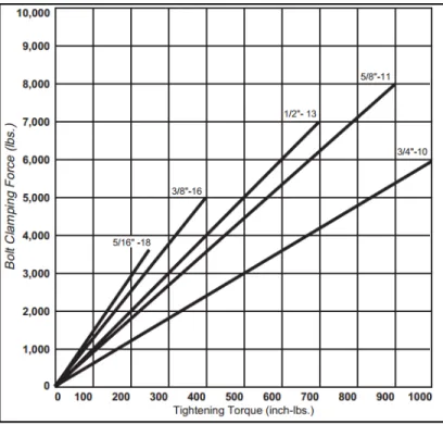
Figure 2.23 Tightening torque (SPAENAUR, 2009)
Based on the numbers in Table 2.3, 25 ft. lbs (300 inch-lbs) torque is selected for this experiment. Producing 2500 lbs load with 5/8 inch bolts (Figure 2.23), and 2500 lbs ( 11500 N).
The threads of the bolts used in the experiment are cleaned and lubricated as required by the manual. A flat washer is selected to each bolt as the manual also recommends (Table 2.4).
Table 2.4 Bolt and washer (SPEARS, 2015)
Flange Size (in.) Bolts Per Kit Diameter (in.)
1-/1/2 4 1/2
2 4 5/8
2-1/2 4 5/8
3 4 5/8
Torque sequence
The bolt torque sequence exhibits the criss-cross pattern 1 of PCC1, shown in Figure 2.24.
Figure 2.24 Torque sequence (SPEARS 2014)
CHAPITRE 3
FINITE ELEMENT MODELING 3.1 Creep model
3.1.1 Introduction
Like other plastic materials, Polyvinyl Chloride (PVC) also exhibits a variety of creep behaviors. For instance, it can be slowly deformed over time when subjected to mechanical stress, even if it is below the yield strength of the material. This phenomenon is known as cold flow.
The creep process has three phases shown in Figure 3.1. In the primary phase the creep starts increasing at a rapid rate and slows with time. Then the secondary creep rate reaches a steady stage followed by the last phase which is tertiary stage with the rate increasing rapidly and terminates when the material breaks or ruptures.
Figure 3.1 Creep strain due to constant applied stress
Creep behavior is an important consideration for the design of PVC products. Creep can result in stress reduction also known as stress relaxation which can affect the load carrying capacity of the product. The dimensions of the product in high-stress zones can also change due to creep. Since creep is time-dependent, applications which are designed with parts that are meant to be loaded for long periods of time may experience unacceptable and permanent deformations or loss of load tightness. Therefore, creep and relaxation are the primary considerations when designing products that undergo continual stress, such as pumps and pressured vessels and pipings (Dropik, Johnson et Roth, 2002).
3.1.2 Creep model in ANSYS
Creep is described as time-dependent plasticity, at a constant stress and temperature which in ANSYS is included in rate-dependent plasticity. Creep is defined as the deformation of materials, which is dependent on time, stress, and temperature. Therefore, creep is understood as the deformation over time of material under load and temperature but is also a function of the neutron flux level in nuclear applications exposed to radiation (SAS IP, 2016). The von Mises stress is used for creep analysis, and the material is assumed to be isotropic for the von Mises potential. The initial-stiffness Newton Raphson Method is used as the basic solution technique.
There are two types of creep rate equations in ANSYS; implicit creep equations and explicit creep equations. The implicit equations are recommended for general application purposes as they are stable, fast, and accurate, especially for long term cases including cases with large creep strain. They can be used to simulate pure creep or creep with isotropic plasticity. The implicit method is more efficient and accurate compared to the explicit method because it can be used to calculate plasticity and creep simultaneously. The temperature-dependent constant is also included in the implicit equations.
The explicit method is recommended for cases with small time steps. Unlike the implicit method, there are no temperature-dependent constants, nor is there simultaneous modeling
45
with any other material models. However, the Arrhenius function can be used for temperature dependency and explicit creep can be combined, with other plasticity options, such as transient analysis, by using superposition modeling for the calculations. In these analyses, the program calculates the plastic before the creep.
There are several studies that have investigated PVC creep, with most of them focusing on the influence of time or tensile stress. In general, such research implements time hardening creep models or strain hardening creep models (Dropik, Johnson et Roth, 2002; Pulngern et al., 2013).
3.1.3 Calculation of creep in ANSYS
In ANSYS the creep option is integrated with the Euler forward method and is efficient for small-scale creep strain analysis. The modified total strain is given by Eq. (3.1).
{ } { }
{ } { } { }
1pl th cr
n n n n n
ε
′ =ε
−ε
−ε
−ε
− (3.1)The equivalent total strain is defined as:
(
) (
)
(
)
1 2 2 2 2 2 2 2 1 3 3 3 ( ) ( ) ( ) 2 2 2 2(1 ) et x y y z z x xy yz zx ε ε ε ε ε ε ε γ γ γ ν ′ ′ ′ ′ ′ ′ ′ ′ ′ = − + − + − + + + + (3.2)The equivalent stress is
e E et
σ = ε (3.3)
The positive equivalent creep strain increment is computed as
1 (1 ) cr m et eA ε ε Δ = − (3.4) Where: e =2.7182(natural logarithms)
cr et A ε ε Δ =
Then, the creep ratio is computed as
cr s et C ε ε Δ = (3.5)
3.1.4 Power law creep model
In this model, creep is assumed to be mainly dependent on the time elapsed, as plastic materials show clear time-dependent creep behavior. The creep model Eq. (3.6) is widely used in creep analysis for such materials. The stress and temperature are also parameters featured in this model.
4 3 2 cr 1 c c c T c t e
ε
=σ
− (3.6)3.2 Bolted flange joint model
The bolted flange joint assembly model is a simplified version of the HOBT fixture that is used in the laboratory, as discussed in chapter 2.3. It consists of an NPS 3 clas 150 PVC flange, a PVC tube and cap, four 5/8 in diameter bolts, lower flange support, and the inner shaft to reduce volume accommodate a cartridge heater in the real joint. The heater is inserted in the shaft in order to provide heat. For the thermal analysis the shaft is heated to the desired temperature.
The flange model used in FE analysis was created based on the machined PVC flange discussed in chapter 2. The material properties of PVC are obtained from tests conducted on small specimen.
47
3.2.1 Geometry model
The geometric features of the flange are shown in Figure 3.2. Due to symetry only a 1/4 bolted joint portion is modeled for the finite element analysis as shown in Figure 3.3.
Figure 3.2 The main fcators of PVC flange
3.2.2 Static model
The model is further reduced to only 1/8 flange joint assembly portion to conduct static analysis. The elements described above are included. The inner shaft and all surrounding air are suppressed in the static analysis. The flange model and test fixture model are shown in Figure 3.4 and Figure 3.5.
Figure 3.4 Expansion flange FEM model
49
Symmetry surfaces
The symmetry surfaces for the static model are at the bolt and between planes as shown in Figure 3.6. The displacements of the points belonging to these planes move only in these planes while the rotations in the radial direction are nil.
Figure 3.6 Symmetry surfaces of static model
Pretension load on bolt
The pre-tension load applied to the bolt is applied through the option of bolt pre-tension, and the load step is listed in Table 3.1. The pre-tension load is applied first and then the position is locked in the subsequent steps.
A coordinate system is created at the center of the bolt bar (Figure 3.7), and is used to apply the bolt load in the axial direction. The bolt load direction is on the y-axis as shown in Figure 3.8.
Figure 3.7 Bolt coordination
Table 3.1 Bolt pre-tension
Steps Define by Preload (N)
1 Load 5426 2 Lock N/A 3 Lock N/A
51
Boundary condition
The vertical displacement of the lower surface of the support and the bolt are constrained in the y-direction, as shown in Figure 3.9. This is justified by the fact that the metallic lower flange support is more rigid than the PVC upper flange.
Figure 3.9 Boundary condition for the static model
3.2.3 CFD model
Because PVC creep is very sensitive to the applied temperature, the heat transfer from the inner flange of the cartridge heater and the central core requires rigorous analysis to provide accurate thermal distributions for the structural model.
The thermal conductive properties of steel and PVC materials being significantly different thermocouples were installed at the inside and outside of the flange to measure the