2020 — A DO-178C-compliant model-driven approach to support the development and certification of safety-critical avionics software
414
0
0
Texte intégral
(2) © Copyright reserved It is forbidden to reproduce, save or share the content of this document either in whole or in parts. The reader who wishes to print or save this document on any media must first get the permission of the author..
(3) BOARD OF EXAMINERS THIS THESIS HAS BEEN EVALUATED BY THE FOLLOWING BOARD OF EXAMINERS. Mrs. Ghizlane El Boussaidi, Thesis Supervisor Département de Génie logiciel et des technologies de l’information École de Technologie Supérieure Mr. Antoine Tahan, President of the Board of Examiners Département de génie mécanique École de Technologie Supérieure Mr. Abdelouahed Gherbi, Member of the jury Département de Génie logiciel et des technologies de l’information École de Technologie Supérieure Mr. Yvan Labiche, External Independent Examiner Systems and Computer Engineering Carleton University. THIS THESIS WAS PRESENTED AND DEFENDED IN THE PRESENCE OF A BOARD OF EXAMINERS AND THE PUBLIC ON FEBRUARY 4, 2020 AT ÉCOLE DE TECHNOLOGIE SUPÉRIEURE.
(4)
(5) to the memory of my beloved grandparents, Cielo and Eduardo to my dear parents, Cielo and Diego.
(6)
(7) PREFACE The research presented hereinafter was conducted in the Laboratoire en Architecture de Système Informatiques at École de Technologie Supérieure, Université du Québec. To the best of my knowledge, this work is original, except where references are made to previous work. Neither this, nor any substantially similar dissertation has been or is being submitted for any other degree, diploma or other qualification at any other university. Parts of this work have been presented in the following publications: A. Paz, G. El Boussaidi and H. Mili, “checsdm: A Method for Ensuring Consistency in Heterogeneous Safety-Critical System Design,” in IEEE Transactions on Software Engineering (Early Access), January 2020. N. Metayer, A. Paz and G. El Boussaidi, “Modelling DO-178C Assurance Needs: A Design Assurance Level-Sensitive DSL,” in Proceedings of the 2019 IEEE International Symposium on Software Reliability Engineering Workshops (ISSREW), October 2019. A. Paz and G. El Boussaidi, “Supporting Consistency in the Heterogeneous Design of Safety-Critical Software,” in Proceedings of the 2019 IEEE 43rd Annual Computer Software and Applications Conference (COMPSAC), July 2019, pp. 37–46. A. Paz and G. El Boussaidi, “A Requirements Modelling Language to Facilitate Avionics Software Verification and Certification,” in Proceedings of the 2019 IEEE/ACM 41st International Conference on Software Engineering Workshops (ICSEW), May 2019, pp. 1–8. A. Paz and G. El Boussaidi, “Building a Software Requirements Specification and Design for an Avionics System: An Experience Report,” in Proceedings of the 33rd Annual ACM Symposium on Applied Computing (SAC’18), April 2018, pp. 1262–1271. A. Paz and G. El Boussaidi, “On the Exploration of Model-Based Support for DO-178C-Compliant Avionics Software Development and Certification,” in Proceedings of the 2016 IEEE International Symposium on Software Reliability Engineering Workshops (ISSREW), October 2016, pp. 229–236..
(8)
(9) ACKNOWLEDGEMENTS My deepest thanks go to my supervisor, Ghizlane El Boussaidi, for an enjoyable and motivating research experience as well as for the trust she placed in me to carry out this work. I am very grateful to her for guiding, encouraging and supporting me throughout the development of this thesis with great competence and scientific rigour. This research was partially supported by the Natural Sciences and Engineering Research Council of Canada (NSERC) (CRDPJ 463076-14) and the Consortium for Research and Innovation in Aerospace in Quebec (CRIAQ) under project AVIO-604. I thank again my supervisor, Ghizlane El Boussaidi, for her financial support throughout the duration of the research. I would like to thank the team of project AVIO-604, especially Pierre, Claire, Martin, Nicolas and Alexis, for their comments and feedback throughout the project, and for helping in the evaluation of the research results. My thanks also go to Hafedh Mili, professor at Université du Québec à Montréal, who was of such a great assistance in shaping this work. I thank the members of the board of examiners for agreeing to evaluate this thesis. I am very thankful to Yvan Labiche, professor at Carleton University, for serving as the external independent examiner and for his useful and constructive comments and feedback. I owe a debt of gratitude to my great friend Hugo Arboleda for preparing me for and encouraging me into pursuing a Ph.D. I will always treasure the life lessons you gave me during the time we spent working together. I would like to thank my friend Camilo Valderrama for his kind words of support. A huge thank you goes to my parents, Cielo and Diego, and my brother, Gustavo, for their unconditional love, support and encouragement. I am extremely grateful to my late grandparents, Cielo and Eduardo, who always supported my studies and gave me so much. I would have never gotten this far without any of you..
(10)
(11) Une Approche Orientée Modèle et Conforme à la Norme DO-178C pour Appuyer le Développement et la Certification des Logiciels d’Avionique Critiques Andrés Felipe PAZ LOBOGUERRERO RÉSUMÉ Les systèmes logiciels, de plus en plus complexes à l’heure actuelle, sont conçus pour répondre aux besoins des domaines dans lesquels la sûreté est cruciale, comme les aéronefs. Cependant, l’ingénierie de logiciels d’avionique n’est pas une tâche simple. D’un côté, les consommateurs demandent l’intégration des fonctionnalités, souvent complexes, pour les rendre plus intelligents. D’un autre côté, leurs environnements opérationnels ont des exigences de sûreté. Pour cette raison, leur ingénierie est hautement réglementée afin de s’assurer qu’ils seront développés d’une manière appropriée pour éviter de nuire aux personnes et aux biens dans leurs environnements opérationnels. Les fournisseurs de systèmes d’avionique doivent fournir des preuves que leurs systèmes sont conformes à la norme réglementaire applicable DO-178C. Ces deux facteurs ont mis en évidence le besoin de techniques d’ingénierie permettant de réduire la complexité du développement et d’appuyer les efforts de certification. Dans ce contexte, l’ingénierie dirigée par les modèles (IDM) représente une alternative plus économique en temps et en coûts. Ceci est principalement dû au fait que les modèles représentent l’information à des niveaux d’abstraction appropriés permettant la manipulation et l’analyse de cette information tout au long du cycle de développement logiciel. Néanmoins, il reste encore des défis importants à relever pour que l’IDM puisse soutenir de manière globale le développement et la certification des systèmes d’avionique, et aussi pour qu’elle soit l’objet d’une adoption à grande échelle. Cette thèse se focalise sur l’investigation de l’IDM pour développer des systèmes hétérogènes où plusieurs langages de modélisation sont utilisés pour exprimer différents aspects du même système. Dans ce contexte, nous investiguons l’utilisation de l’IDM pour assurer: 1) la cohérence entre les modèles de conception, 2) la traçabilité des élements de ces modèles par rapport aux exigences, et 3) une relation explicite entre toutes ces informations et les objectifs réglementaires de la DO-178C. Pour faire face à ces défis, nous proposons une méthode, basée sur l’IDM, qui supporte la cohérence entre modèles de conception hétérogènes et fournit une infrastructure de spécification des exigences. Toutes les données produites par cette méthode sont traçables aux objectifs réglementaires de la DO-178C. Afin d’arriver à cette contribution, nous avons examiné diverses approches de modélisation pour la conception hétérogène et la gestion de la cohérence. Nous avons construit une méthode systématique et automatisée pouvant être appliquée à une variété de scénarios de conception impliquant différents langages de modélisation et directives de conception. Les méthodes de modélisation de conception hétérogènes existantes peuvent être utilisées dans la méthode proposée. En outre, nous avons étudié certains langages de modélisation des exigences utilisés dans le contexte des systèmes critiques. Nous avons analysé le support que ces langages offrent pour faciliter la certification et capturer des informations structurées et sémantiquement.
(12) XII. riches permettant des analyses et des tests basés sur les exigences. En se basant sur les résultats de cette étude, nous avons construit un langage de modélisation des exigences qui combine certain nombre des langages étudiés et qui s’intègre dans notre méthode. À ce propos, nous avons suivi une approche systématique pour construire un tel langage de modélisation. Nous avons réalisé des évaluations empiriques de notre méthode par le biais d’études de cas. Nous avons fait également des ateliers avec des praticiens industriels en vue d’évaluer leurs perceptions de la méthode proposée. Les résultats obtenus dans ces évaluations nous permettent de conclure que la méthode proposée dans cette thèse, peut être utilisée efficacement pour appuyer le développement et la certification des logiciels d’avionique selon la norme DO-178C. En particulier, les praticiens industriels considèrent qu’elle est facile à comprendre et qu’il y a une forte probabilité qu’ils l’adoptent dans le contexte de leur travail. Mots-clés: Ingénierie dirigée par les modèles, systèmes critiques, systèmes d’avionique, conception hétérogène, spécification des exigences, certification, DO-178C..
(13) A DO-178C-compliant Model-Driven Approach to Support the Development and Certification of Safety-Critical Avionics Software Andrés Felipe PAZ LOBOGUERRERO ABSTRACT Increasingly complex software is nowadays engineered to cater to safety-critical domains, like aircraft. However, engineering software for avionics systems is not a straightforward task. On one hand, consumer demands have spurred the need to pack features in, often intricate ones that will make systems smarter. On the other hand is the safety-critical nature of their operational environments. Because of this, their engineering is highly regulated in order to ensure they are developed appropriately to avoid, or at least mitigate, posing undue harm to anyone or anything in their operational environments. Avionics systems manufacturers are, thus, obliged to provide the appropriate software safety assurance in compliance with the applicable regulatory norm DO-178C. These two factors have pointed toward the need of engineering techniques that aid in reducing development complexities and support certification endeavours. Model-Driven Engineering (MDE) has been proposed as a cost- and time-effective alternative. The main rationale behind MDE is that models represent information at the right levels of abstraction to enable reasoning and ease information manipulation throughout the entire engineering life cycle. Nonetheless, significant challenges must still be overcome for MDE to comprehensively support the development and certification of avionics systems, and experience widespread adoption. This thesis focuses on the investigation of MDE for supporting the use of different modelling languages for describing the same system while ensuring 1) consistency between the different system models, 2) traceability of the elements in such models back to requirements, and 3) all of this information explicitly relates to DO-178C regulatory objectives. Given these challenges, the main contribution of this thesis is a systematic and automated method, based on MDE, for assisting engineering teams in ensuring consistency of heterogeneous design models and providing such teams with a requirements specification infrastructure. All outputs of the method are explicitly traceable to DO-178C regulatory objectives. To arrive at this contribution, we reviewed various heterogeneous design modelling and consistency management approaches. We derived a systematic and automated method that can be applied to various design scenarios involving different modelling languages and different design guidelines. Existing heterogeneous design modelling approaches can be leveraged within our proposed method. Furthermore, we studied several requirements modelling languages used in the context of safety-critical systems and characterized their support toward enforcing information for DO-178C certification and capturing structured semantically-rich information to enable requirements-based analyses and testing. Based on the results from such a survey we advocated for the combination of several of these languages to build a modelling language that could be integrated into the proposed method. We followed a systematic approach to build such a modelling language. We undertook empirical evaluations of our proposal by applying.
(14) XIV. it in two case studies. As part of the evaluations we also include assessment workshops with practitioners from industry to examine their perceptions about it. The results from the empirical evaluations show that our proposal can be effectively used to support the development and certification of avionics software in accordance with DO-178C. Practitioners from industry consider the proposal to be easy to understand and gave it an overall likelihood of adoption within the contexts of their work. Keywords: Model-Driven Engineering, safety-critical systems, avionics systems, heterogeneous design, requirements specification, certification, DO-178C..
(15) TABLE OF CONTENTS Page INTRODUCTION . . . . . . . . . . . . . . . . . . . . . . . . . . . . . . . . . . . . . . . . . . . . . . . . . . . . . . . . . . . . . . . . . . . . . . . . . . . . . . . . 1 CHAPTER 1 BACKGROUND AND LITERATURE REVIEW . . . . . . . . . . . . . . . . . . . . . . . . . 23 1.1 Software Considerations in Airborne Systems and Equipment Certification . . . . . . . . 23 1.1.1 DO-178C . . . . . . . . . . . . . . . . . . . . . . . . . . . . . . . . . . . . . . . . . . . . . . . . . . . . . . . . . . . . . . . . . . . . . . 24 1.1.2 DO-331 . . . . . . . . . . . . . . . . . . . . . . . . . . . . . . . . . . . . . . . . . . . . . . . . . . . . . . . . . . . . . . . . . . . . . . . . 28 1.1.3 DO-332 . . . . . . . . . . . . . . . . . . . . . . . . . . . . . . . . . . . . . . . . . . . . . . . . . . . . . . . . . . . . . . . . . . . . . . . . 29 1.2 Model-Driven Engineering (MDE) . . . . . . . . . . . . . . . . . . . . . . . . . . . . . . . . . . . . . . . . . . . . . . . . . . . . . 30 1.2.1 Modelling . . . . . . . . . . . . . . . . . . . . . . . . . . . . . . . . . . . . . . . . . . . . . . . . . . . . . . . . . . . . . . . . . . . . . 30 1.2.2 Modelling with Simulink and Stateflow . . . . . . . . . . . . . . . . . . . . . . . . . . . . . . . . . . . . . 32 1.2.3 Modelling with AADL . . . . . . . . . . . . . . . . . . . . . . . . . . . . . . . . . . . . . . . . . . . . . . . . . . . . . . . 34 1.2.4 Modelling with UML . . . . . . . . . . . . . . . . . . . . . . . . . . . . . . . . . . . . . . . . . . . . . . . . . . . . . . . . . 34 1.2.5 Methodology for developing modelling languages for regulation certification using UML . . . . . . . . . . . . . . . . . . . . . . . . . . . . . . . . . . . . . . . . . . . . . . . . . . . . . . 36 1.3 Model-Based Approaches Supporting Safety-Critical System Development and Certification . . . . . . . . . . . . . . . . . . . . . . . . . . . . . . . . . . . . . . . . . . . . . . . . . . . . . . . . . . . . . . . . . . . . . . . . . 37 1.3.1 Approaches supporting certification . . . . . . . . . . . . . . . . . . . . . . . . . . . . . . . . . . . . . . . . . 39 1.3.1.1 Meta-approaches . . . . . . . . . . . . . . . . . . . . . . . . . . . . . . . . . . . . . . . . . . . . . . . . . . 39 1.3.1.2 Safety assurance cases . . . . . . . . . . . . . . . . . . . . . . . . . . . . . . . . . . . . . . . . . . . . 41 1.3.1.3 Certification-compliant system design and analysis . . . . . . . . . . . . . 43 1.3.2 Approaches supporting requirements specifications . . . . . . . . . . . . . . . . . . . . . . . . 46 1.3.2.1 Natural language-based specification . . . . . . . . . . . . . . . . . . . . . . . . . . . . 47 1.3.2.2 Behavioural modelling . . . . . . . . . . . . . . . . . . . . . . . . . . . . . . . . . . . . . . . . . . . . 51 1.3.2.3 Hybrid specification . . . . . . . . . . . . . . . . . . . . . . . . . . . . . . . . . . . . . . . . . . . . . . . 53 1.3.3 Approaches handling design model heterogeneity . . . . . . . . . . . . . . . . . . . . . . . . . . 58 1.3.3.1 Model composition . . . . . . . . . . . . . . . . . . . . . . . . . . . . . . . . . . . . . . . . . . . . . . . 59 1.3.3.2 Model integration . . . . . . . . . . . . . . . . . . . . . . . . . . . . . . . . . . . . . . . . . . . . . . . . . 60 1.3.3.3 Consistency management . . . . . . . . . . . . . . . . . . . . . . . . . . . . . . . . . . . . . . . . . 63 1.4 Discussion . . . . . . . . . . . . . . . . . . . . . . . . . . . . . . . . . . . . . . . . . . . . . . . . . . . . . . . . . . . . . . . . . . . . . . . . . . . . . . . 64 1.4.1 Approaches supporting certification . . . . . . . . . . . . . . . . . . . . . . . . . . . . . . . . . . . . . . . . . 65 1.4.2 Approaches supporting requirements specification in the context of certifiable safety-critical systems development . . . . . . . . . . . . . . . . . . . . . . . . . . . 66 1.4.3 Approaches handling design model heterogeneity . . . . . . . . . . . . . . . . . . . . . . . . . . 70 1.5 Chapter Summary . . . . . . . . . . . . . . . . . . . . . . . . . . . . . . . . . . . . . . . . . . . . . . . . . . . . . . . . . . . . . . . . . . . . . . . 71 CHAPTER 2 THE LANDING GEAR CONTROL SOFTWARE . . . . . . . . . . . . . . . . . . . . . . . . 73 2.1 Related Work . . . . . . . . . . . . . . . . . . . . . . . . . . . . . . . . . . . . . . . . . . . . . . . . . . . . . . . . . . . . . . . . . . . . . . . . . . . . 74 2.2 Plan for Software Aspects of Certification (PSAC) . . . . . . . . . . . . . . . . . . . . . . . . . . . . . . . . . . . 76 2.2.1 System overview . . . . . . . . . . . . . . . . . . . . . . . . . . . . . . . . . . . . . . . . . . . . . . . . . . . . . . . . . . . . . . 76 2.2.2 Certification considerations . . . . . . . . . . . . . . . . . . . . . . . . . . . . . . . . . . . . . . . . . . . . . . . . . . 79.
(16) XVI. 2.3 2.4. 2.5. 2.6. 2.2.3 Development methodology . . . . . . . . . . . . . . . . . . . . . . . . . . . . . . . . . . . . . . . . . . . . . . . . . . . 81 Software Requirements Data . . . . . . . . . . . . . . . . . . . . . . . . . . . . . . . . . . . . . . . . . . . . . . . . . . . . . . . . . . . 87 Design Description . . . . . . . . . . . . . . . . . . . . . . . . . . . . . . . . . . . . . . . . . . . . . . . . . . . . . . . . . . . . . . . . . . . . . . 89 2.4.1 Software architecture . . . . . . . . . . . . . . . . . . . . . . . . . . . . . . . . . . . . . . . . . . . . . . . . . . . . . . . . . 89 2.4.2 Low-level requirements (LLRs) . . . . . . . . . . . . . . . . . . . . . . . . . . . . . . . . . . . . . . . . . . . . . . 92 Discussion . . . . . . . . . . . . . . . . . . . . . . . . . . . . . . . . . . . . . . . . . . . . . . . . . . . . . . . . . . . . . . . . . . . . . . . . . . . . . . . 95 2.5.1 Requirements specification . . . . . . . . . . . . . . . . . . . . . . . . . . . . . . . . . . . . . . . . . . . . . . . . . . . 95 2.5.1.1 Quality and granularity of SRATS . . . . . . . . . . . . . . . . . . . . . . . . . . . . . . . 95 2.5.1.2 Requirements specification language . . . . . . . . . . . . . . . . . . . . . . . . . . . . 96 2.5.2 Design . . . . . . . . . . . . . . . . . . . . . . . . . . . . . . . . . . . . . . . . . . . . . . . . . . . . . . . . . . . . . . . . . . . . . . . . . 97 2.5.2.1 Design modelling language . . . . . . . . . . . . . . . . . . . . . . . . . . . . . . . . . . . . . . . 97 2.5.2.2 Granularity of LLRs . . . . . . . . . . . . . . . . . . . . . . . . . . . . . . . . . . . . . . . . . . . . . . 97 2.5.2.3 Bidirectional traces in model-based LLRs . . . . . . . . . . . . . . . . . . . . . . . 98 2.5.2.4 Consistency of heterogeneous design models . . . . . . . . . . . . . . . . . . . 99 Chapter Summary . . . . . . . . . . . . . . . . . . . . . . . . . . . . . . . . . . . . . . . . . . . . . . . . . . . . . . . . . . . . . . . . . . . . . .100 CHECSDM: CONSISTENCY OF HETEROGENEOUS EMBEDDED CONTROL SYSTEM DESIGN MODELS . . . . . . . . . . . . . . . . . . . . . . . . . . . . . . . .103 The checsdm Approach . . . . . . . . . . . . . . . . . . . . . . . . . . . . . . . . . . . . . . . . . . . . . . . . . . . . . . . . . . . . . . . .103 3.1.1 Elicitation phase . . . . . . . . . . . . . . . . . . . . . . . . . . . . . . . . . . . . . . . . . . . . . . . . . . . . . . . . . . . . .105 3.1.1.1 Mix of modelling languages . . . . . . . . . . . . . . . . . . . . . . . . . . . . . . . . . . . . .105 3.1.1.2 Mapping rules . . . . . . . . . . . . . . . . . . . . . . . . . . . . . . . . . . . . . . . . . . . . . . . . . . . .107 3.1.1.3 Design guidelines . . . . . . . . . . . . . . . . . . . . . . . . . . . . . . . . . . . . . . . . . . . . . . . .108 3.1.2 Codification phase . . . . . . . . . . . . . . . . . . . . . . . . . . . . . . . . . . . . . . . . . . . . . . . . . . . . . . . . . . .109 3.1.2.1 Metamodelling . . . . . . . . . . . . . . . . . . . . . . . . . . . . . . . . . . . . . . . . . . . . . . . . . . .110 3.1.2.2 Codification of mapping rules . . . . . . . . . . . . . . . . . . . . . . . . . . . . . . . . . . .111 3.1.2.3 Codification of design guidelines . . . . . . . . . . . . . . . . . . . . . . . . . . . . . . .112 3.1.3 Operation phase . . . . . . . . . . . . . . . . . . . . . . . . . . . . . . . . . . . . . . . . . . . . . . . . . . . . . . . . . . . . . .113 checsdm4uss: Concrete Instantiation of checsdm . . . . . . . . . . . . . . . . . . . . . . . . . . . . . . . . . . . .115 3.2.1 checsdm4uss: Elicitation phase . . . . . . . . . . . . . . . . . . . . . . . . . . . . . . . . . . . . . . . . . . . . .116 3.2.1.1 Mix of modelling languages . . . . . . . . . . . . . . . . . . . . . . . . . . . . . . . . . . . . .116 3.2.1.2 Mapping rules . . . . . . . . . . . . . . . . . . . . . . . . . . . . . . . . . . . . . . . . . . . . . . . . . . . .117 3.2.1.3 Design guidelines . . . . . . . . . . . . . . . . . . . . . . . . . . . . . . . . . . . . . . . . . . . . . . . .120 3.2.2 checsdm4uss: Codification phase . . . . . . . . . . . . . . . . . . . . . . . . . . . . . . . . . . . . . . . . . . .124 3.2.2.1 Metamodelling . . . . . . . . . . . . . . . . . . . . . . . . . . . . . . . . . . . . . . . . . . . . . . . . . . .124 3.2.2.2 Codification of mapping rules . . . . . . . . . . . . . . . . . . . . . . . . . . . . . . . . . . .125 3.2.2.3 Codification of design guidelines . . . . . . . . . . . . . . . . . . . . . . . . . . . . . . .126 3.2.2.4 Derived toolchain . . . . . . . . . . . . . . . . . . . . . . . . . . . . . . . . . . . . . . . . . . . . . . . .128 3.2.3 checsdm4uss: Operation phase . . . . . . . . . . . . . . . . . . . . . . . . . . . . . . . . . . . . . . . . . . . . . .128 3.2.3.1 Step 1: Software specification . . . . . . . . . . . . . . . . . . . . . . . . . . . . . . . . . . .128 3.2.3.2 Step 2: Software design . . . . . . . . . . . . . . . . . . . . . . . . . . . . . . . . . . . . . . . . . .129 3.2.3.3 Step 3: Verification of intra-model design guideline compliance . . . . . . . . . . . . . . . . . . . . . . . . . . . . . . . . . . . . . . . . . . . . . . . . . . . . . . .129. CHAPTER 3 3.1. 3.2.
(17) XVII. 3.2.3.4 3.2.3.5. 3.3. Step 4: Mapping of design models . . . . . . . . . . . . . . . . . . . . . . . . . . . . . .129 Step 5: Verification of inter-model design guideline compliance . . . . . . . . . . . . . . . . . . . . . . . . . . . . . . . . . . . . . . . . . . . . . . . . . . . . . . .131 Chapter Summary . . . . . . . . . . . . . . . . . . . . . . . . . . . . . . . . . . . . . . . . . . . . . . . . . . . . . . . . . . . . . . . . . . . . . .133. CHAPTER 4 4.1 4.2. 4.3. 4.4. 4.5. SPECML: REQUIREMENTS SPECIFICATION MODELLING LANGUAGE . . . . . . . . . . . . . . . . . . . . . . . . . . . . . . . . . . . . . . . . . . . . . . . . . . . . . . . . . . . . . . . .135 Methodology for Developing SpecML . . . . . . . . . . . . . . . . . . . . . . . . . . . . . . . . . . . . . . . . . . . . . . . .136 SpecML’s Domain Metamodel . . . . . . . . . . . . . . . . . . . . . . . . . . . . . . . . . . . . . . . . . . . . . . . . . . . . . . . .137 4.2.1 Requirements-related concepts . . . . . . . . . . . . . . . . . . . . . . . . . . . . . . . . . . . . . . . . . . . . . .138 4.2.2 Requirement formalization-related concepts . . . . . . . . . . . . . . . . . . . . . . . . . . . . . . .142 SpecML as a UML Profile . . . . . . . . . . . . . . . . . . . . . . . . . . . . . . . . . . . . . . . . . . . . . . . . . . . . . . . . . . . . .144 4.3.1 Profile organization . . . . . . . . . . . . . . . . . . . . . . . . . . . . . . . . . . . . . . . . . . . . . . . . . . . . . . . . . .144 4.3.2 Profile stereotypes . . . . . . . . . . . . . . . . . . . . . . . . . . . . . . . . . . . . . . . . . . . . . . . . . . . . . . . . . . .144 4.3.2.1 Requirement hierarchy . . . . . . . . . . . . . . . . . . . . . . . . . . . . . . . . . . . . . . . . . . .145 4.3.2.2 Requirement interrelationship . . . . . . . . . . . . . . . . . . . . . . . . . . . . . . . . . . .151 4.3.2.3 Requirement formalization . . . . . . . . . . . . . . . . . . . . . . . . . . . . . . . . . . . . . .152 4.3.2.4 Data dictionary . . . . . . . . . . . . . . . . . . . . . . . . . . . . . . . . . . . . . . . . . . . . . . . . . . .156 Reference Implementation . . . . . . . . . . . . . . . . . . . . . . . . . . . . . . . . . . . . . . . . . . . . . . . . . . . . . . . . . . . . .157 4.4.1 Tool support . . . . . . . . . . . . . . . . . . . . . . . . . . . . . . . . . . . . . . . . . . . . . . . . . . . . . . . . . . . . . . . . . .157 4.4.2 Overview . . . . . . . . . . . . . . . . . . . . . . . . . . . . . . . . . . . . . . . . . . . . . . . . . . . . . . . . . . . . . . . . . . . . .158 Chapter Summary . . . . . . . . . . . . . . . . . . . . . . . . . . . . . . . . . . . . . . . . . . . . . . . . . . . . . . . . . . . . . . . . . . . . . .160. CHAPTER 5 EVALUATION . . . . . . . . . . . . . . . . . . . . . . . . . . . . . . . . . . . . . . . . . . . . . . . . . . . . . . . . . . . . . .163 5.1 Research Questions . . . . . . . . . . . . . . . . . . . . . . . . . . . . . . . . . . . . . . . . . . . . . . . . . . . . . . . . . . . . . . . . . . . .163 5.2 RQ-1: Feasibility of checsdm’s Execution . . . . . . . . . . . . . . . . . . . . . . . . . . . . . . . . . . . . . . . . . . . .165 5.2.1 Data collection procedure . . . . . . . . . . . . . . . . . . . . . . . . . . . . . . . . . . . . . . . . . . . . . . . . . . .165 5.2.2 checsdm4a/ss—Another concrete instantiation of checsdm . . . . . . . . . . . . . . .166 5.2.3 Results and analysis . . . . . . . . . . . . . . . . . . . . . . . . . . . . . . . . . . . . . . . . . . . . . . . . . . . . . . . . . .169 5.3 RQ-2: checsdm4uss vs. Manual Verification . . . . . . . . . . . . . . . . . . . . . . . . . . . . . . . . . . . . . . . . .173 5.3.1 Data collection procedure . . . . . . . . . . . . . . . . . . . . . . . . . . . . . . . . . . . . . . . . . . . . . . . . . . .173 5.3.2 Design models . . . . . . . . . . . . . . . . . . . . . . . . . . . . . . . . . . . . . . . . . . . . . . . . . . . . . . . . . . . . . . .176 5.3.3 Results and analysis . . . . . . . . . . . . . . . . . . . . . . . . . . . . . . . . . . . . . . . . . . . . . . . . . . . . . . . . . .178 5.4 RQ-3: Feasibility of SpecML’s Use . . . . . . . . . . . . . . . . . . . . . . . . . . . . . . . . . . . . . . . . . . . . . . . . . . .183 5.4.1 Data collection procedure . . . . . . . . . . . . . . . . . . . . . . . . . . . . . . . . . . . . . . . . . . . . . . . . . . .183 5.4.2 Results and analysis . . . . . . . . . . . . . . . . . . . . . . . . . . . . . . . . . . . . . . . . . . . . . . . . . . . . . . . . . .184 5.5 RQ-4: Likelihood of industry adoption . . . . . . . . . . . . . . . . . . . . . . . . . . . . . . . . . . . . . . . . . . . . . . .190 5.5.1 Data collection procedure . . . . . . . . . . . . . . . . . . . . . . . . . . . . . . . . . . . . . . . . . . . . . . . . . . .190 5.5.2 Results and analysis . . . . . . . . . . . . . . . . . . . . . . . . . . . . . . . . . . . . . . . . . . . . . . . . . . . . . . . . . .191 5.6 Threats to Validity . . . . . . . . . . . . . . . . . . . . . . . . . . . . . . . . . . . . . . . . . . . . . . . . . . . . . . . . . . . . . . . . . . . . . .197 5.6.1 Internal validity . . . . . . . . . . . . . . . . . . . . . . . . . . . . . . . . . . . . . . . . . . . . . . . . . . . . . . . . . . . . . .197 5.6.2 External validity . . . . . . . . . . . . . . . . . . . . . . . . . . . . . . . . . . . . . . . . . . . . . . . . . . . . . . . . . . . . . .199 5.7 Chapter Summary . . . . . . . . . . . . . . . . . . . . . . . . . . . . . . . . . . . . . . . . . . . . . . . . . . . . . . . . . . . . . . . . . . . . . .201.
(18) XVIII. CONCLUSION AND OUTLOOK . . . . . . . . . . . . . . . . . . . . . . . . . . . . . . . . . . . . . . . . . . . . . . . . . . . . . . . . . . . .203 APPENDIX I. THE CHARACTERIZATION FRAMEWORK . . . . . . . . . . . . . . . . . . . . . . . . . . .211. APPENDIX II LANDING GEAR CONTROL SOFTWARE REQUIREMENTS SPECIFICATION AND DESIGN (BASELINE) . . . . . . . . . . . . . . . . . . . . . . . . . .217 APPENDIX III MAPPING RULES AND DESIGN GUIDELINES OF CHECSDM4USS . . . . . . . . . . . . . . . . . . . . . . . . . . . . . . . . . . . . . . . . . . . . . . . . . . . . . . . . . . . . . . . . . . . . .257 APPENDIX IV CHECSDM AND CHECSDM4USS DEVELOPER’S AND USER’S GUIDES . . . . . . . . . . . . . . . . . . . . . . . . . . . . . . . . . . . . . . . . . . . . . . . . . . . . . . . . . . .275 APPENDIX V BREEZE THROUGH SAFETY-CRITICAL SYSTEM MODELBASED DESIGN WITH EMF, SIMULINK AND STATEFLOW . . . . . . . .297 APPENDIX VI SPECML DOMAIN CONCEPTS . . . . . . . . . . . . . . . . . . . . . . . . . . . . . . . . . . . . . . . . . .307 APPENDIX VII SPECML STEREOTYPES . . . . . . . . . . . . . . . . . . . . . . . . . . . . . . . . . . . . . . . . . . . . . . . . .323 APPENDIX VIIISPECML DEVELOPER’S AND USER’S GUIDES . . . . . . . . . . . . . . . . . . . . .345 BIBLIOGRAPHY . . . . . . . . . . . . . . . . . . . . . . . . . . . . . . . . . . . . . . . . . . . . . . . . . . . . . . . . . . . . . . . . . . . . . . . . . . . . . .373.
(19) LIST OF TABLES Page Table 1.1. Summary of model-based approaches supporting requirements specification . . . . . . . . . . . . . . . . . . . . . . . . . . . . . . . . . . . . . . . . . . . . . . . . . . . . . . . . . . . . . . . . . . . . . . 68. Table 1.2. Summary of model-based approaches supporting requirements specification (Continued) . . . . . . . . . . . . . . . . . . . . . . . . . . . . . . . . . . . . . . . . . . . . . . . . . . . . . . . . 68. Table 1.3. Summary of model-based approaches supporting requirements specification (Continued) . . . . . . . . . . . . . . . . . . . . . . . . . . . . . . . . . . . . . . . . . . . . . . . . . . . . . . . . 69. Table 2.1. Examples of SRATS for the LGCS. . . . . . . . . . . . . . . . . . . . . . . . . . . . . . . . . . . . . . . . . . . . . . 88. Table 2.2. Examples of HLRs for the LGCS. Adapted from Paz & El Boussaidi (2018). . . . . . . . . . . . . . . . . . . . . . . . . . . . . . . . . . . . . . . . . . . . . . . . . . . . . . . . . . . . . . . . . . . . . . . . . . . . . 89. Table 2.3. Examples of LLRs for the LGCS. Extracted from Paz & El Boussaidi (2018).. . . . . . . . . . . . . . . . . . . . . . . . . . . . . . . . . . . . . . . . . . . . . . . . . . . . . . . . . . . . . . . . . 93. Table 3.1. Summary of mapping rules for checsdm4uss. . . . . . . . . . . . . . . . . . . . . . . . . . . . . . . . . .118. Table 3.2. Mapping rule mr_us_03 for UML components and Simulink subsystems. Extracted from Paz et al. (2020). . . . . . . . . . . . . . . . . . . . . . . . . . . . . . . . . .118. Table 3.3. Mapping rule mr_us_05 for UML input parameters and Simulink block inputs. Extracted from Paz et al. (2020). . . . . . . . . . . . . . . . . . . . . . . . . . . . . . . . .120. Table 3.4. Summary of design guidelines for checsdm4uss.. . . . . . . . . . . . . . . . . . . . . . . . . . . . . .121. Table 3.5. Design guideline av_us_01: Mixed use of UML, Simulink and Stateflow. Extracted from Paz et al. (2020). . . . . . . . . . . . . . . . . . . . . . . . . . . . . . . . . . . .122. Table 3.6. Design guideline av_us_03: Naming of elements in UML models. Extracted from Paz et al. (2020). . . . . . . . . . . . . . . . . . . . . . . . . . . . . . . . . . . . . . . . . . . . . . . .122. Table 3.7. Design guideline av_us_10: Expression of triggers appearing in both UML and Stateflow transitions. Extracted from Paz et al. (2020). . . . . . . . . . . . . . . . . . . . . . . . . . . . . . . . . . . . . . . . . . . . . . . . . . . . . . . . . . . . . . . . . . . . . . . . . . . .123. Table 5.1. Summary of the mapping rules for checsdm4a/ss. . . . . . . . . . . . . . . . . . . . . . . . . . . . .167. Table 5.2. Mapping rule mr_as_02 for AADL process implementation and Simulink subsystem. . . . . . . . . . . . . . . . . . . . . . . . . . . . . . . . . . . . . . . . . . . . . . . . . . . . . . . . . . . . .167.
(20) XX. Table 5.3. Summary of design guidelines for checsdm4a/ss. . . . . . . . . . . . . . . . . . . . . . . . . . . . . .168. Table 5.4. Design guideline av_as_09: Specification of AADL process as a Simulink subsystem block. . . . . . . . . . . . . . . . . . . . . . . . . . . . . . . . . . . . . . . . . . . . . . . . . . . . . .169. Table 5.5. Summary of the checsdm instantiations. Extracted from Paz et al. (2020). . . . . . . . . . . . . . . . . . . . . . . . . . . . . . . . . . . . . . . . . . . . . . . . . . . . . . . . . . . . . . . . . . . . . . . . . . . .170. Table 5.6. Effort involved in the elicitation phases of the checsdm instantiations. Extracted from Paz et al. (2020).. . . . . . . . . . . . . . . . . . . . . . . . . . . . . . .171. Table 5.7. Effort involved in the codification phases of the checsdm instantiations. Extracted from Paz et al. (2020).. . . . . . . . . . . . . . . . . . . . . . . . . . . . . . .172. Table 5.8. Pre-study survey. Extracted from Paz et al. (2020). . . . . . . . . . . . . . . . . . . . . . . . . . . .174. Table 5.9. Inconsistency report sheet. Extracted from Paz et al. (2020). . . . . . . . . . . . . . . . .175. Table 5.10. Fragment example of a mapping model inspection sheet. Extracted from Paz et al. (2020). . . . . . . . . . . . . . . . . . . . . . . . . . . . . . . . . . . . . . . . . . . . . . . . . . . . . . . . . . .176. Table 5.11. Post-study survey. Extracted from Paz et al. (2020). . . . . . . . . . . . . . . . . . . . . . . . . . .176. Table 5.12. Summary of the design models for the LGCS, FCS and ECS. Extracted from Paz et al. (2020). . . . . . . . . . . . . . . . . . . . . . . . . . . . . . . . . . . . . . . . . . . . . . . .177. Table 5.13. Summary of checsdm4uss’ resulting mapping models for the LGCS, FCS and ECS. . . . . . . . . . . . . . . . . . . . . . . . . . . . . . . . . . . . . . . . . . . . . . . . . . . . . . . . . . . . . . . . . . . .178. Table 5.14. Summary of checsdm4uss’ resulting mappings for the LGCS, FCS and ECS. Extracted from Paz et al. (2020). . . . . . . . . . . . . . . . . . . . . . . . . . . . . . . . . . . . .179. Table 5.15. Summary of inconsistencies manually reported by the control group for the LGCS, FCS and ECS. Extracted from Paz et al. (2020). . . . . . . . . . . . . . .181. Table 5.16. Requirements extracted from the LGCS and FCS. . . . . . . . . . . . . . . . . . . . . . . . . . . . .184. Table 5.17. Pre-workshop survey. . . . . . . . . . . . . . . . . . . . . . . . . . . . . . . . . . . . . . . . . . . . . . . . . . . . . . . . . . . .191. Table 5.18. GQM model for the assessment workshop. . . . . . . . . . . . . . . . . . . . . . . . . . . . . . . . . . . . .192.
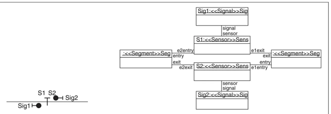
(21) LIST OF FIGURES Page Figure 0.1. Suggested DO-178C development life cycle. . . . . . . . . . . . . . . . . . . . . . . . . . . . . . . . . . . 4. Figure 0.2. Research methodology. . . . . . . . . . . . . . . . . . . . . . . . . . . . . . . . . . . . . . . . . . . . . . . . . . . . . . . . . . 13. Figure 0.3. Overview of the approach.. . . . . . . . . . . . . . . . . . . . . . . . . . . . . . . . . . . . . . . . . . . . . . . . . . . . . . 15. Figure 1.1. DO-178C detailed software development workflow. . . . . . . . . . . . . . . . . . . . . . . . . . . 27. Figure 1.2. Scope of DO-331 within DO-178C. Adapted from Rad (2011b). . . . . . . . . . . . . 29. Figure 1.3. OMG’s four-level modelling framework. Adapted from OMG (2013). . . . . . . . . . . . . . . . . . . . . . . . . . . . . . . . . . . . . . . . . . . . . . . . . . . . . . . . . . . . . . . . . . . . . . . . . . . . 32. Figure 1.4. Example of the Simulink notation. Extracted from Paz et al. (2020). . . . . . . . . . . . . . . . . . . . . . . . . . . . . . . . . . . . . . . . . . . . . . . . . . . . . . . . . . . . . . . . . . . . . . . . . . . . 33. Figure 1.5. Example of the Stateflow notation. Extracted from Paz et al. (2020). . . . . . . . . . . . . . . . . . . . . . . . . . . . . . . . . . . . . . . . . . . . . . . . . . . . . . . . . . . . . . . . . . . . . . . . . . . . 33. Figure 1.6. AADL graphical notation for the example in Listing 1.1. . . . . . . . . . . . . . . . . . . . . 35. Figure 1.7. Methodology for developing UML-based DSMLs for regulation certification. Extracted from Metayer et al. (2019). . . . . . . . . . . . . . . . . . . . . . . . . . . 38. Figure 1.8. Process for managing and collecting certification information. Adapted from Panesar-Walawege et al. (2013). . . . . . . . . . . . . . . . . . . . . . . . . . . . . . . . 40. Figure 1.9. Fragment of an object diagram for a tramway network design. Extracted from Berkenkötter & Hannemann (2006). . . . . . . . . . . . . . . . . . . . . . . . . . 44. Figure 1.10. State machine diagram using OMEGA-RT for an aircraft’s flight control computer sensor. Adapted from IST (2001). . . . . . . . . . . . . . . . . . . . . . . . . . . 45. Figure 1.11. Toolchain based on commercially available tools. Adapted from Eisemann (2016). . . . . . . . . . . . . . . . . . . . . . . . . . . . . . . . . . . . . . . . . . . . . . . . . . . . . . . . . . 46. Figure 1.12. Fragment of the UML profile’s metamodel by Zoughbi et al. (2011). Adapted from Zoughbi et al. (2011). . . . . . . . . . . . . . . . . . . . . . . . . . . . . . . . . . 49. Figure 1.13. Fragment of the RDAL metamodel. Adapted from Blouin (2013). . . . . . . . . . . 51.
(22) XXII. Figure 1.14. Fragment of a requirement specification for a sensor using ReqSpec. Adapted from Feiler et al. (2016). . . . . . . . . . . . . . . . . . . . . . . . . . . . . . . . . . . 51. Figure 1.15. High-level RSML specification for the TCAS II. Extracted from Leveson et al. (1994).. . . . . . . . . . . . . . . . . . . . . . . . . . . . . . . . . . . . . . . . . . . . . . . . . . . . . 53. Figure 1.16. UCM behavioural model for a landing gear controller. . . . . . . . . . . . . . . . . . . . . . . . 54. Figure 1.17. Structure of an HCT (left) and an example (right). Extracted from Bialy et al. (2015) and Bialy et al. (2017), respectively. . . . . . . . . . . . . . . . . 55. Figure 1.18. SpeAR specification for a thermostat. Extracted from Fifarek et al. (2017). . . . . . . . . . . . . . . . . . . . . . . . . . . . . . . . . . . . . . . . . . . . . . . . . . . . . . . . . . . . . . . . . . . . . . . . . . . . 56. Figure 1.19. Formalization of an HLR for a car’s automatic light system using STIMULUS. Adapted from Gaucher & Génevaux (2017). . . . . . . . . . . . . . . . . . . . 57. Figure 1.20. Architecture of the UML profile for MARTE. Adapted from OMG (2011). . . . . . . . . . . . . . . . . . . . . . . . . . . . . . . . . . . . . . . . . . . . . . . . . . . . . . . . . . . . . . . . . . . . . . . . . . . . 58. Figure 1.21. Development process for the ATP system in the Metrô Rio. Extracted from Ferrari et al. (2013). . . . . . . . . . . . . . . . . . . . . . . . . . . . . . . . . . . . . . . . . . . . 62. Figure 1.22. Proposed development flow by Tanaka et al. (2017). Extracted from Kuroki et al. (2016). . . . . . . . . . . . . . . . . . . . . . . . . . . . . . . . . . . . . . . . . . . . . . . . . . . . . . . 62. Figure 1.23. The ARCADIA engineering approach. Extracted from Roques (2016). . . . . . . . . . . . . . . . . . . . . . . . . . . . . . . . . . . . . . . . . . . . . . . . . . . . . . . . . . . . . . . . . . . . . . . . . . . . 63. Figure 2.1. Illustration of an aircraft’s landing gear system. Adapted from Paz & El Boussaidi (2017). . . . . . . . . . . . . . . . . . . . . . . . . . . . . . . . . . . . . . . . . . . . . . . 77. Figure 2.2. System overview. Extracted from Paz & El Boussaidi (2018). . . . . . . . . . . . . . . . 78. Figure 2.3. Illustration of the main states of a wheel assembly (from left to right): gear extended, gear in transit and gear retracted. Adapted from Paz & El Boussaidi (2017). . . . . . . . . . . . . . . . . . . . . . . . . . . . . . . . . . . . . . . . . . . . . . . 79. Figure 2.4. General flow for requirements specification and design. Extracted from Paz & El Boussaidi (2018). . . . . . . . . . . . . . . . . . . . . . . . . . . . . . . . . . . . . . . . . . . . . . . 82. Figure 2.5. Expanded view of the Develop HLRs activity. Extracted from Paz & El Boussaidi (2018). . . . . . . . . . . . . . . . . . . . . . . . . . . . . . . . . . . . . . . . . . . . . . . 83. Figure 2.6. Expanded view of the Develop Software Architecture activity. Adapted from Paz & El Boussaidi (2018). . . . . . . . . . . . . . . . . . . . . . . . . . . . . . . . . . . . . 85.
(23) XXIII. Figure 2.7. Expanded view of the Develop LLRs activity for specifying textual LLRs. Adapted from Paz & El Boussaidi (2018).. . . . . . . . . . . . . . . . . . . . . . . . . . . . . 86. Figure 2.8. Expanded view of the Develop LLRs activity for specifying LLRs as design models. Adapted from Paz & El Boussaidi (2018). . . . . . . . . . . . . . . . . 87. Figure 2.9. Architecture for the LGCS as a UML component diagram. Adapted from Paz & El Boussaidi (2018). . . . . . . . . . . . . . . . . . . . . . . . . . . . . . . . . . . . . 90. Figure 2.10. ControlData interface. Extracted from Paz et al. (2020). . . . . . . . . . . . . . . . . . . . 91. Figure 2.11. Excerpt of the architecture for the LGCS as a Simulink block diagram. . . . . . . . . . . . . . . . . . . . . . . . . . . . . . . . . . . . . . . . . . . . . . . . . . . . . . . . . . . . . . . . . . . . . . . . . . 92. Figure 2.12. Excerpt from the UML state machine associated to the SequenceController component. Adapted from Paz et al. (2020). . . . . . . . . . 94. Figure 2.13. LGCS decomposition as a Simulink block diagram. Extracted from Paz et al. (2020). . . . . . . . . . . . . . . . . . . . . . . . . . . . . . . . . . . . . . . . . . . . . . . . . . . . . . . . . . . 94. Figure 2.14. Excerpt from the Stateflow chart realizing the SequenceController subsystem block. Extracted from Paz et al. (2020). . . . . . . . . . . . . . 95. Figure 3.1. General flow of the checsdm approach. Adapted from Paz et al. (2020). . . . . . . . . . . . . . . . . . . . . . . . . . . . . . . . . . . . . . . . . . . . . . . . . . . . . . . . . . . . . . . . . . . . . . . . . . .104. Figure 3.2. Feature model characterizing the mix of modelling languages. Extracted from Paz et al. (2020).. . . . . . . . . . . . . . . . . . . . . . . . . . . . . . . . . . . . . . . . . . . . . .106. Figure 3.3. Mapping rules metamodel. Extracted from Paz et al. (2020). . . . . . . . . . . . . . . .108. Figure 3.4. Mapping metamodel. Extracted from Paz et al. (2020). . . . . . . . . . . . . . . . . . . . . .108. Figure 3.5. Guidelines metamodel. Extracted from Paz et al. (2020). . . . . . . . . . . . . . . . . . . .109. Figure 3.6. The checsdm tool framework. Extracted from Paz et al. (2020). . . . . . . . . . . . .111. Figure 3.7. Flow of the operation phase. Adapted from Paz et al. (2020). . . . . . . . . . . . . . .114. Figure 3.8. Excerpt from the LGCS design models illustrating the application of mapping rules mr_us_03, mr_us_05 and mr_us_06. Extracted from Paz et al. (2020). . . . . . . . . . . . . . . . . . . . . . . . . . . . . . . . . . . . . . . . . . . . . . . . . . . . . . . . . .119. Figure 3.9. Illustrative example for applying guideline av_us_10. Extracted from Paz et al. (2020). . . . . . . . . . . . . . . . . . . . . . . . . . . . . . . . . . . . . . . . . . . . . . . . . . . . . . . . . .123.
(24) XXIV. Figure 3.10. Overview of the derived toolchain for checsdm4uss. Extracted from Paz et al. (2020). . . . . . . . . . . . . . . . . . . . . . . . . . . . . . . . . . . . . . . . . . . . . . . . . . . . . . . . . .129. Figure 3.11. Screenshot of the resulting checsdm4uss mapping model for the LGCS and the properties of the selected mapping in line 3. Extracted from Paz et al. (2020).. . . . . . . . . . . . . . . . . . . . . . . . . . . . . . . . . . . . . . . . . . . . . .130. Figure 3.12. Excerpts from the UML state machine associated to the SequenceController component and the Stateflow chart associated to the SequenceController subsystem block. Adapted from Figures 2.12 and 2.14. . . . . . . . . . . . . . . . . . . . . . . . . . . . . . . . . . . . . . . . . . . . . . . . . . . .132. Figure 3.13. Screenshot of design guideline av_us_10’s violation. Extracted from Paz et al. (2020). . . . . . . . . . . . . . . . . . . . . . . . . . . . . . . . . . . . . . . . . . . . . . . . . . . . . . . . . .132. Figure 4.1. Methodology for developing SpecML. Adapted from Figure 1.7. . . . . . . . . . .137. Figure 4.2. Fragment of SpecML’s domain metamodel showing the requirements concepts. . . . . . . . . . . . . . . . . . . . . . . . . . . . . . . . . . . . . . . . . . . . . . . . . . . . . . . . .139. Figure 4.3. Fragment of SpecML’s domain metamodel showing the formalization concepts. . . . . . . . . . . . . . . . . . . . . . . . . . . . . . . . . . . . . . . . . . . . . . . . . . . . . . . . .143. Figure 4.4. Requirement hierarchy stereotypes. . . . . . . . . . . . . . . . . . . . . . . . . . . . . . . . . . . . . . . . . . . .146. Figure 4.5. Excerpt of the LGCS specification model using SpecML showing SRATS-2 and HLR-2. . . . . . . . . . . . . . . . . . . . . . . . . . . . . . . . . . . . . . . . . . . . . . . . . . . . . . . . . .152. Figure 4.6. Requirement interrelationship stereotypes. . . . . . . . . . . . . . . . . . . . . . . . . . . . . . . . . . . .153. Figure 4.7. Excerpt of the LGCS specification model using SpecML showing the interrelationship between SRATS-2 and HLR-2.. . . . . . . . . . . . . . . . . . . . . . . . .153. Figure 4.8. Requirement formalization stereotypes. . . . . . . . . . . . . . . . . . . . . . . . . . . . . . . . . . . . . . .154. Figure 4.9. Excerpt of the LGCS specification model using SpecML showing one of the formalizations for HLR-2. . . . . . . . . . . . . . . . . . . . . . . . . . . . . . . . . . . . . . . . . .155. Figure 4.10. Excerpt of the LGCS specification model using SpecML showing timed constraint formalizations.. . . . . . . . . . . . . . . . . . . . . . . . . . . . . . . . . . . . . . . . . . . . . . .156. Figure 4.11. Data dictionary stereotypes. . . . . . . . . . . . . . . . . . . . . . . . . . . . . . . . . . . . . . . . . . . . . . . . . . . .157. Figure 4.12. Excerpt of the LGCS specification model using SpecML showing two data entries from the data dictionary. . . . . . . . . . . . . . . . . . . . . . . . . . . . . . . . . . . . .157.
(25) XXV. Figure 4.13. Screenshot of the SpecML reference implementation. Extracted from Paz & El Boussaidi (2019b). . . . . . . . . . . . . . . . . . . . . . . . . . . . . . . . . . . . . . . . . . . . .159. Figure 4.14. Fragment of the specification model for the LGCS in the reference implementation. . . . . . . . . . . . . . . . . . . . . . . . . . . . . . . . . . . . . . . . . . . . . . . . . . . . . . . . . . . . . . . . .160. Figure 4.15. Fragment of the specification model for the LGCS in the reference implementation’s tabular view. . . . . . . . . . . . . . . . . . . . . . . . . . . . . . . . . . . . . . . . . . . . . . . . .161. Figure 5.1. Overview of the derived toolchain for checsdm4a/ss. . . . . . . . . . . . . . . . . . . . . . . . .169. Figure 5.2. Participants’ background. Extracted from Paz et al. (2020). . . . . . . . . . . . . . . . .174. Figure 5.3. Example of an injected inconsistency used in the study. Adapted from Paz et al. (2020). . . . . . . . . . . . . . . . . . . . . . . . . . . . . . . . . . . . . . . . . . . . . . . . . . . . . . . . . .178. Figure 5.4. Comparison of the consolidated inconsistency recall. Extracted from Paz et al. (2020). . . . . . . . . . . . . . . . . . . . . . . . . . . . . . . . . . . . . . . . . . . . . . . . . . . . . . . . . .181. Figure 5.5. Post-study survey results for Q1 and Q2. CG: Control Group. OG: Operation Group. Extracted from Paz et al. (2020). . . . . . . . . . . . . . . . . . . . . . . . . .182. Figure 5.6. Post-study survey results for Q3, Q4 and Q5. Extracted from Paz et al. (2020).. . . . . . . . . . . . . . . . . . . . . . . . . . . . . . . . . . . . . . . . . . . . . . . . . . . . . . . . . . . . . . . . . . . .182. Figure 5.7. Post-study survey results for Q6. Extracted from Paz et al. (2020). . . . . . . . .183. Figure 5.8. Fragment of the specification model for the LGCS. . . . . . . . . . . . . . . . . . . . . . . . . .185. Figure 5.9. Complete formalization of the LGCS’ HLR-2 in SpecML’s reference implementation. . . . . . . . . . . . . . . . . . . . . . . . . . . . . . . . . . . . . . . . . . . . . . . . . . . . . .186. Figure 5.10. Tabular view for the complete formalization of the LGCS’ HLR-2 in SpecML’s reference implementation. . . . . . . . . . . . . . . . . . . . . . . . . . . . . . . . . . . . . . .187. Figure 5.11. Fragment of the specification model for the FCS. Extracted from Paz & El Boussaidi (2019b). . . . . . . . . . . . . . . . . . . . . . . . . . . . . . . . . . . . . . . . . . . . . . . . . . .188. Figure 5.12. Screenshot of the specification and formalization of HLR_4 for the FCS with the SpecML reference implementation. Extracted from Paz & El Boussaidi (2019b). . . . . . . . . . . . . . . . . . . . . . . . . . . . . . . . . . . . . . . . . . . . . . . . . . .188. Figure 5.13. SysML parametric diagram of the CommandLoopControlPredicate constraint block. . . . . . . . . . . . . . . . . . . . . . . . . . . . . . . . . . . . . . . . . . . . . . . . . . . .189. Figure 5.14. Q1. Were (1) checsdm [and] (2) checsdm4uss easy to understand? . . . . . . . . .193.
(26) XXVI. Figure 5.15. Q1. [Was] (3) SpecML easy to understand? . . . . . . . . . . . . . . . . . . . . . . . . . . . . . . . . . .193. Figure 5.16. Q2. Would you use (1) checsdm [and] (2) checsdm4uss to help in your work? . . . . . . . . . . . . . . . . . . . . . . . . . . . . . . . . . . . . . . . . . . . . . . . . . . . . . . . . . . . . . . . . . . . . .193. Figure 5.17. Q2. Would you use (3) SpecML to help in your work? . . . . . . . . . . . . . . . . . . . . . .194. Figure 5.18. Q3. Do you see value in adopting (1) checsdm and (2) checsdm4uss for ensuring consistency of heterogeneous design models? . . . . . . . . . . . . . . . . .194. Figure 5.19. Q4. Do you see value in adopting SpecML for supporting (1) requirement specification, (2) requirement-based testing, and (3) certification efforts?. . . . . . . . . . . . . . . . . . . . . . . . . . . . . . . . . . . . . . . . . . . . . . . . . . . . . . . . . . . .194. Figure 5.20. Q5. Does the resulting mapping model in the operation phase provide useful assistance for reviewing and solving consistency issues in heterogeneous design models? . . . . . . . . . . . . . . . . . . . . . . . . . . . . . . . . . . . . . .195. Figure 5.21. Q6. Do you find the resulting requirements specification model simple enough for use when communicating with a certification agent? . . . . . . . . . . . . . . . . . . . . . . . . . . . . . . . . . . . . . . . . . . . . . . . . . . . . . . . . . . . . . . . . . . . . . . . . . . .195. Figure 5.22. Q7. Does the proposed approach provide useful assistance for adhering to certification compliance needs? . . . . . . . . . . . . . . . . . . . . . . . . . . . . . . . . . .196.
(27) LISTINGS Page Listing 1.1. Example of the AADL textual notation. . . . . . . . . . . . . . . . . . . . . . . . . . . . . . . . . . . . . . . 35. Listing 3.1. Codification of mapping rule mr_us_03. Extracted from Paz et al. (2020). . . . . . . . . . . . . . . . . . . . . . . . . . . . . . . . . . . . . . . . . . . . . . . . . . . . . . . . . . . . . . . . . . . . . . . . . . .126. Listing 3.2. Codification of intra-model design guideline av_us_03. Extracted from Paz et al. (2020). . . . . . . . . . . . . . . . . . . . . . . . . . . . . . . . . . . . . . . . . . . . . . . . . . . . . . . . . .127. Listing 3.3. Codification of inter-model design guideline av_us_10. Extracted from Paz et al. (2020). . . . . . . . . . . . . . . . . . . . . . . . . . . . . . . . . . . . . . . . . . . . . . . . . . . . . . . . . .128.
(28)
(29) LIST OF ABREVIATIONS AADL. Architecture Analysis and Design Language. API. Application programming interface. Breesse. Bridge for the Eclipse Modeling Framework ecosystem and the MathWorks Simulink and Stateflow ecosystem. CFC. Contribution to failure condition. checsdm. Consistency of Heterogeneous Embedded Control System Design Models. checsdm4a/ss. Consistency of Heterogeneous Embedded Control System Design Models for AADL, Simulink and Stateflow. checsdm4uss. Consistency of Heterogeneous Embedded Control System Design Models for UML, Simulink and Stateflow. CRIAQ. Consortium de Recherche et d’Innovation en Aérospatiale au Québec. DSML. Domain-specific modelling language. EASA. European Aviation Safety Agency. ECL. Epsilon Comparison Language. ECS. Elevator control system. EMF. Eclipse Modeling Framework. EOL. Epsilon Object Language. EUROCAE. European Organisation for Civil Aviation Equipment. EV. hydraulic electro-valve. FAA. US Federal Aviation Administration.
(30) XXX. FCS. Flight control system. GQM. Goal-question-metric. HCT. Horizontal Condition Tables. HLR. High-level requirement. IDM. Ingénierie dirigée par les modèles. JWI. Java WordNet interface. kPa. kilo-Pascal. LGCS. Landing gear control software. LGS. Landing gear system. LLR. Low-level requirement. LTL. Linear Temporal Logic. MAAB. MathWorks Automotive Advisory Board. MARTE. Modeling and Analysis of Real-Time Embedded Systems. MDE. Model-Driven Engineering. MOF. Meta-Object Facility. MPM. Multi-Paradigm Modeling. OCL. Object Constraint Language. OEM. Original Equipment Manufacturers. OMG. Object Management Group. OOT. Object-Oriented Technology.
(31) XXXI. OSLC. Open Services for Lifecycle Collaboration. PBR. Property-based requirement. PID. Proportional-integral-derivative. PIM. Platform-independent model. PLE. Product Line Engineering. PSAC. Plan for Software Aspects of Certification. PSM. Platform-specific model. pw. Person week(s). RAF. Reference Assurance Framework. RDAL. Requirements Definition and Analysis Language. RQ. Research question. RSML. Requirements State Machine Language. RTCA. Radio Technical Commission for Aeronautics. SACM. Structured Assurance Case Metamodel. SH. System hazard. SMT. Satisfiability modulo theory. SpeAR. Specification and Analysis of Requirements. SpecML. Requirements Specification Modeling Language. SRATS. System requirement allocated to software. SysML. Systems Modeling Language.
(32) XXXII. TCAS II. Traffic Collision Avoidance System level II. TDL. Test Description Language. UCM. Use Case Map. UI. User Interface. UML. Unified Modeling Language. VQL. Viatra Query Language. V&V. Verification and Validation.
(33) INTRODUCTION Over the past decades, safety-critical avionics systems have increasingly grown in size and complexity. They even have become decisive drivers for innovation in aircraft (acatech, 2011). The advent of software as the behavioural controller for such systems has, indeed, made this largely possible (Spitzer, 2007; Sztipanovits, 2007; Huhn & Hungar, 2007). However, engineering avionics software is a complex task. On the one hand, current consumer demands have spurred the need to pack features in. In recurrent instances, some intricate ones intended to make the systems smarter. On the other hand, safety is a major concern. Avionics software must operate in sensitive environments. Therefore, its engineering is highly regulated in order to ensure it is developed appropriately to avoid, or at least mitigate, undue harm to anyone or anything in their operational environments. Avionics systems manufacturers are, thus, obliged to provide the appropriate software safety assurance in compliance with the applicable regulatory norm DO-178C. There has been increasing work around more up-to-date, effective engineering techniques and technologies to aid avionics systems manufacturers in reducing development complexities and to support them in their certification endeavors (Pettit et al., 2014; McGregor et al., 2017). The increased need for automation tools and interoperability have pointed practitioners from industry, and academics alike, toward Model-Driven Engineering (MDE). Selic (2003) defines a model as a reduced (i.e. simplified, abstract) representation of some (aspect of a) system that highlights its properties of interest from a given viewpoint. MDE was developed around the premise to turn models into first-class artifacts across the entire engineering life cycle in an attempt at delivering high quality systems in the most productive way (Schmidt, 2006). In order to keep up with such a premise, MDE makes use of domain-specific modelling languages (DSMLs) to provide users with a working environment where they can directly manipulate domain concepts (Kelly & Tolvanen, 2007). MDE’s gained popularity has been due to its costand time-effectiveness (Huhn & Hungar, 2007). The main rationale explaining this is that.
(34) 2. models represent information at the right levels of abstraction to enable reasoning and ease information manipulation throughout the entire engineering life cycle. Nonetheless, significant challenges must still be overcome for MDE to comprehensively support the development and certification of avionics systems, and experience widespread adoption in such a safety-critical domain. The remainder of this chapter presents the precise context of our research, states the research problem that was addressed, sets out the objectives for this thesis, describes the methodology followed to achieve such objectives, and summarizes the contributions made. Finally, it outlines the organization of the rest of the dissertation.. Research Context This thesis has been motivated in direct response to the development and certification needs of two Canadian companies as part of CRIAQ1 project AVIO-604. The companies are large suppliers of safety-critical systems, many of which are avionics systems subject to certification compliance with DO-178C (Rad, 2011a), and its DO-331 (Rad, 2011b) and DO-332 (Rad, 2011c) supplements. The Radio Technical Commission for Aeronautics (RTCA) along with its European counterpart, the European Organisation for Civil Aviation Equipment (EUROCAE), have issued the joint DO-178C/ED-12C guideline (Rad, 2011a). The guideline represents best development and safety practices that have been followed to produce safe avionics software systems (Esposito et al., 2011; Areias et al., 2014). Certification authorities around the globe such as the United States Federal Aviation Administration (FAA), the European Aviation Safety Agency (EASA) and Transport Canada have adopted DO-178C as the primary—but not the only— 1. Consortium de Recherche et d’Innovation en Aérospatiale au Québec.
(35) 3. compliance means for approving software airworthiness2 . Hence, DO-178C associates an accredited certification schemata, meaning it establishes a stringent certification process seeking to achieve a high level of confidence in the airborne software’s capabilities under normal and abnormal operations (Rad, 2011a). In particular, the document defines the development methodology as well as the proper qualitative and quantitative evidence necessary for assessing the fulfillment of the system’s intended purpose (Esposito et al., 2011; Ceccarelli & Silva, 2013). The guideline largely suggests following a V-Model life cycle (Huhn & Hungar, 2007; Heimdahl, 2007; Ceccarelli & Silva, 2013; Areias et al., 2014; Özçelik & Altilar, 2015; McGregor et al., 2017). This is on the grounds that its sequential nature and strong emphasis on verification and validation activities and traceability for each phase promotes a meticulous design and implementation in order to build a safe system. Figure 0.1 illustrates the V-Model and its phases. The downward segment of the V-Model, the development flow, comprises three major phases or process groups: Requirements, Design, and Source Code and Executable Object Code (Rad, 2011a). The upward segment of the V-Model corresponds to Verification & Validation (V&V). V&V is considered transverse to the system development and must be requirements-based, meaning verification cases exist for checking and ensuring that the resulting system meets its specified requirements (both high-level and low-level). Other transverse processes (not illustrated) are Planning and Certification Liaison. This thesis focuses on a subset of these life cycle processes, namely Requirements and Design, and part of the V&V related to the previous two processes. Roughly speaking, the prescribed V-Model flow is executed as follows. Development begins with the analysis of system requirements allocated to software (SRATS). Safety and hazard assessments are not performed as part of the scope of DO-178C, although their findings are taken 2. Reliability and safe-to-use in flight..
(36) 4. System Requirements Allocated To Software Development flow. Verification & Validation flow. High-Level Requirements. High-Level Requirements. Design (Low-Level requirements). Design (Low-Level requirements). Source Code / Executable Object Code Regulatory scope of DO-178C. Figure 0.1. Suggested DO-178C development life cycle.. as inputs in this activity. Such SRATS must be developed (i.e. refined and decomposed) into high-level software requirements (HLRs). A review of the HLRs validates these against the system and safety requirements allocated to software to check if their intent is being accurately captured by the HLRs in a way suitable for directing software design activities. The correct specification of HLRs initiates the design and, in parallel, the creation of requirements-based test cases, test vectors and oracles (i.e. expected outputs). The design covers the definition of the architecture and the specification of low-level requirements (LLRs) (i.e. the detailed design). LLRs, together with the architecture, are used to guide the coding and building activities. LLRs and architecture must conform to design standards. Design standards specify methods, notations, rules, constraints, guidelines, and conventions to be used in the development of the design models. They can be specific to the company or inferred from DO-178C. Test cases are used to verify that both the LLRs and the realized software’s behaviour meet the specified HLRs. In addition, reviews of the software realization itself validate that it meets the design..
(37) 5. One of the major changes of DO-178C from its predecessor is the included guidance on modern development and verification practices such as MDE, Object-Oriented technologies (OOT) and formal methods. All of these changes are provided as technology supplement documents, DO331, DO-332 and DO-333, respectively, adapting the core DO-178C standard for the applicable technologies. The focus of the industry partners was on using MDE technologies to support their development and certification efforts. Thus, the DO-331 supplement became applicable. Although the DO-332 supplement is particularly intended for the software coding and integration processes, compliance with its guidance also becomes relevant when using object-oriented modelling languages like UML, which provide constructs for representing OOT features, e.g., inheritance, polymorphism, overloading. MDE has been considered for developing avionics software with different purposes in multiple ways (e.g., Zoughbi et al. (2011); Wu et al. (2015); de la Vara et al. (2016)). Such approaches have varying aims, scopes, usages and outputs. They may focus on the following challenges in one or more of the life cycle’s processes (Nair et al., 2014; de la Vara et al., 2016): 1) overcoming communication and understanding issues among the primary stakeholders, 2) supporting or automating development activities (e.g., design), or 3) managing and collecting information for certification or compliance assessments. Special certification considerations must be taken into account for the second challenge, i.e. when parts of the system under construction are to be expressed using models (Potter, 2012; Pettit et al., 2014). Models may be used for software analysis, verification, simulation or code generation (Potter, 2012). Two types of models are addressed in DO-331: specification models and design models. The former represent system requirements and HLRs, and the latter represent LLRs and architecture. Engineers may leverage these different models during development, however, they must remain mindful that these models represent requirements and therefore must be treated as such under DO-178C (Potter, 2012). Models even have.
(38) 6. to frequently coexist alongside natural language specifications. Especially, design models of avionics systems are characterized by the diversity of modelling languages used as a result of the multiple aspects that need to be captured (e.g., computation, control, physical processes) (Sjöstedt et al., 2008; Huang et al., 2018).. Problem Statement The research problem is framed by the conditions set by the industry partners; in essence: safety-critical avionics systems whose design is represented using different modelling languages (e.g., UML, Simulink and Stateflow; AADL, Simulink and Stateflow). Thus, we state the research problem as follows: Effectively designing avionics systems requires the combination of diverse modelling languages for modelling the entirety of aspects that need to be covered. However, to be compliant with DO-178C, there must be explicit documentation that 1) each set of corresponding elements from different design models exhibit the same features and behaviour, 2) the design models conform to design standards, and 3) bidirectional traceability exists between requirements and design.. To direct our work we refined this problem into two subproblems:. P-1. Design information that is spread across multiple models and expressed in different modelling languages must be consistent. Avionics systems are complex systems combining physical and mechanical components, networking and software (Lee, 2010). Effectively designing such systems requires a complex modelling approach that can cope with 1) dealing with diverse components, including mechanical, electronic and software, each one of these with its own underlying theories and domain vocabularies, and 2) dealing with various aspects of the same component, such as their function, structure and behaviour. It is already hard enough to relate information presented in the different software model views, e.g., linking states.
(39) 7. and transitions in a state machine to classes and methods, or system functions to packages, classes and methods. It is even harder to relate information that is spread across multiple models and expressed in different modelling languages (Lee, 2010; Eker et al., 2003; Yu et al., 2011; Combemale et al., 2014; van den Brand & Groote, 2015). Ensuring consistency between heterogeneous design models is an important problem, in and of itself. Adding to that are the stringent quality and verification objectives and activities of certification standards, guidelines and norms. In this regard are the following four objectives: the detailed design is accurate and consistent, the detailed design conforms to design standards, the software architecture is consistent, and the software architecture conforms to design standards. A number of existing studies have addressed mapping relationships between heterogeneous modelling languages (e.g., Farkas et al. (2009); Sakairi et al. (2012); Bombino & Scandurra (2013); Ferrari et al. (2013); Sjöstedt et al. (2008); Tanaka et al. (2017)). However, they target pairs of specific modelling languages without devising a general approach. Other existing studies deal with consistency management in heterogeneous design models (e.g., Finkelstein et al. (1994); Almeida da Silva et al. (2010); Dijkman et al. (2008); El Hamlaoui et al. (2018)) but do not explicitly provide the syntactical and semantical relationships between them. Furthermore, none of these studies tackle the issue of verifying conformance to design standards. Establishing model consistency and adherence to design standards are resource-consuming and error-prone activities. While automated design verification and validation tools can help, they cannot be used in isolation. Indeed, if the output of such tools is not manually verified by a human being, then the tools themselves need to be qualified, i.e. they need to be subjected to the same—if not a higher—level of scrutiny as the systems they are meant to verify (Varró, 2016)..
(40) 8. P-2. Requirements must be modelled in such a way that they exhibit an explicit relationship with the objectives and activities of DO-178C and its DO-331 and DO-332 supplements. Furthermore, modelled requirements must support the extraction of information from which reusable verification cases can be generated. In all of the development life cycle presented in the previous section, requirements and requirements-based verification are two of the foremost development concerns for avionics software certification under DO-178C. Indeed, the most stringent compliance needs of DO-178C are centred around 1) requirements specification, 2) the proper argumentation and traceability of such requirements to design decisions and certification objectives and activities, and 3) the verification of the resulting system against the specified requirements. The majority of errors found in avionics systems usually have their origin in the Requirements phase (Feiler, 2010). Nevertheless, over 50% of them are only detected and corrected in the final phases of development (Feiler, 2010). Verification activities may end up driving a cost equivalent to seven times that of the other development activities (Moy et al., 2013). Current industry practices have requirements specified using constrained natural language and managed with the help of textual requirements databases, like IBM DOORS (Potter, 2012; Blouin, 2013). Although the use of a constrained natural language brings some discipline and rigour to requirement specifications, this practice is still focused on writing requirements in human-readable prose. This inevitably raises problems for satisfying the objectives and activities of DO-178C. Natural language indeed facilitates communication between stakeholders but it is not a suitable form of specification for supporting interrelationships, decomposition, requirements-based analyses and testing (Moy et al., 2013). Several requirements specification languages were proposed for safety-critical systems development (e.g., Zoughbi et al. (2011); Stallbaum & Rzepka (2010); Leveson et al..
(41) 9. (1994); Micouin (2008); Blouin (2013); Bialy et al. (2015); Fifarek et al. (2017)). Others, like SysML (OMG, 2017a) and MARTE (OMG, 2011) were introduced for system and real-time system engineering, respectively, but have been employed in safetycritical systems development. Some of these languages only support the specification of natural language-based requirements (e.g., OMG (2017a); Zoughbi et al. (2011); Stallbaum & Rzepka (2010)). Others allow the expression of semantically richer requirement statements using formal notations (e.g., Leveson et al. (1994); Micouin (2008); Bialy et al. (2015); Fifarek et al. (2017)). However, the use of formal notations alone restrains their adoption even when they can enable requirements-based analyses and testing. Moreover, none of these languages provides sufficient support for achieving DO-178C objectives and activities, for instance, by identifying a requirement’s place in DO-178C’s requirements hierarchy (i.e. SRATS, HLR, LLR).. Research Objectives Our main goal is to build an approach to support the development and certification of safetycritical avionics systems. In particular, we want to build on the progress made in MDE technologies to safeguard consistency of heterogeneous design models and enable requirementsbased analyses and verification of safety-critical avionics systems in a way that yields evidence for certification. To do so, we refine this main objective as follows:. O-1 Define a systematic and automated method for assisting engineering teams in ensuring consistency of heterogeneous design models of safety-critical avionics systems. Effective safety-critical avionics system design requires a heterogeneity of modelling mechanisms focused around specific system aspects (e.g., mechanical, electronic, software), each having its own underlying domain theories and vocabularies, as well as with various aspects of the same component (e.g., function, structure, behaviour). However,.
Figure


+7


Documents relatifs
This graphical editor corresponding to our SoSSec DSML (Fig. 6) could now be used by SoS security architects to model their SoS taking into account its specific characteristics
Dans cette thèse, nous présentons une méthodologie du cycle de vie de développement et un ensemble de techniques et d’outils associés, en vue de la conception de systèmes
In this process, a great attention is given to traceability analysis, which allows verifying all the links among Acquirer and Other Stakeholder Requirements, Technical and
Chapitre I: Introduction aux ressources humaines et au management dans la banque Introduction Section 1 : Aperçu sur les Ressources Humaines et banque I- Connaissance des
Our approach thus can be used to obtain formal patterns to capture a set of samples; properties that distinguish positive from neg- ative samples; guide to refine a concept
We chose the ADIRS- inspired case study as it allowed us to demonstrate a number of domain-specific concepts that we integrated in the test meta- model (e.g.,
Our proposed framework, called GRaViTY [6], supports de- velopers in applying the model-driven development approach, as described in Sec. II-A, to the development and maintenance
أﻣـﺎ ﻋـن اﻟﻣﻧﮭـﺞ اﻟﻣﺗﺑـﻊ ،ﻓﮭـو اﻟﻣﻧﮭـﺞ اﻟﺗـﺎرﯾﺧﻲ أي اﻟﻣﻧﮭـﺞ اﻟﻧﻘـﻠﻲ اﻹﺳﺗـردادي ،اﻟـوﺛﺎﺋﻘﻲ، واﻟﻣﻧﮭـﺞ اﻻﺳﺗﻧﺑـﺎطﻲ اﻟـذي ﯾﻘـوم ﻋﻠـﻰ
