Science Arts & Métiers (SAM)
is an open access repository that collects the work of Arts et Métiers Institute of
Technology researchers and makes it freely available over the web where possible.
This is an author-deposited version published in:
https://sam.ensam.eu
Handle ID: .
http://hdl.handle.net/10985/18537
To cite this version :
Aleksander KAROLCZUK, Jan PAPUGA, Thierry PALIN-LUC - Progress in fatigue life calculation
by implementing life-dependent material parameters in multiaxial fatigue criteria - International
Journal of Fatigue - Vol. 134, p.105509 - 2020
Any correspondence concerning this service should be sent to the repository
Administrator :
[email protected]
is an open access repository that collects the work of Arts et Métiers ParisTech
researchers and makes it freely available over the web where possible.
This is an author-deposited version published in:
https://sam.ensam.eu
Handle ID: .
http://hdl.handle.net/null
To cite this version :
Aleksander KAROLCZUK, Jan PAPUGA, Thierry PALIN-LUC - Progress in fatigue life calculation
by implementing life-dependent material parameters in multiaxial fatigue criteria - International
Journal of Fatigue - Vol. 134, p.105509 - 2020
Contents lists available atScienceDirect
International Journal of Fatigue
journal homepage:www.elsevier.com/locate/ijfatigueProgress in fatigue life calculation by implementing life-dependent material
parameters in multiaxial fatigue criteria
Aleksander Karolczuk
a,⁎, Jan Papuga
b, Thierry Palin-Luc
caOpole University of Technology, ul. Mikołajczyka 5, 45-271 Opole, Poland bCzech Technical University in Prague, Technická 4, 166 07, Prague 6, Czech Republic cArts et Metiers ParisTech, I2M, CNRS, Universite de Bordeaux, Talence Cedex, France
A R T I C L E I N F O
Keywords:
Multiaxial fatigue criteria Fatigue life calculation
Cyclic loading, life-dependent material parameters
2124-T851 aluminium alloy
A B S T R A C T
This paper presents the concept of applying life-dependent material parameters to several multiaxial fatigue criteria. This concept reflects the transformation of damage mechanisms in relation to the applied load level, and also in relation to the varying level of plasticity. The goal of this study is to demonstrate the benefit of in-troducing life-dependent material parameters into stress-based multiaxial fatigue criteria for predicting the fa-tigue life of materials. New experimental results of fafa-tigue tests on 2124-T851 aluminium alloy confirm the advantage of the life-dependent concept in life assessment over the concept withfixed weight parameters.
1. Introduction
Non-monotonic variation of the stress state due to thermal or me-chanical loading can lead to permanent changes in the microstructure of a material and to the development of a fatigue crack. Research performed since the pioneering works in the 19th century, as com-mented e.g. by Schütz[1], has revealed that the fatigue phenomenon is a very complex and multiscale problem. In order to overcome this problem in the design process of mechanical structures, the applic-ability of the proposed fatigue damage models is often restricted to a given material type, loading condition, temperature, fatigue life regime, etc., that are close to the conditions for which the model was verified. It has been observed that engineering practice makes particularly ex-tensive use of the least complex models. There has been a tendency to modify these models and to extend their operating range. As a result, a large number of multiaxial fatigue damage models have been developed in recent decades[2–8]. Damage models dealing with the multiaxial stress state problem include a function to reduce the spatial strain/ stress state to a scalar value of the equivalent damage. In the fatigue life calculation algorithm, this scalar value is compared with the appro-priate reference fatigue characteristics, resulting in an estimate of the fatigue life. This relatively simple methodology has gained considerable popularity, and several new models have been proposed[9–23]in just the last few years. Apart from a small number of exceptions discussed below, the proposed models assume that the material parameters ap-plied in the multiaxial stress-reducing function are constant. These
parameters are used to weight the different influence of the tensile and shear stress/strain state components in the damage development in the material. Their values are found by applying experimental data, mostly under uniaxial loadings, to the proposed stress- or strain-based reducing function. Extensive research carried out by Socie[24]revealed that the weight of the shear or tensile damage mechanisms in thefinal failure depends on the loading and on the type of material, and also on the fatigue life. In general, Socie[24]observed that for 304 stainless steel, Inconel 718 and 1045 steel, the crack nucleation period controlled by the shear stress increases with increasing fatigue life.
The material parameters used in multiaxial stress state reduction function are life-dependent, if the ratio of torsion to axial fatigue strengths changes along with the number of cycles to failure. Some light could be shed on the physical basis of this effect through an analysis of the ratio of torsion to the push-pull fatigue limits on smooth specimens, and its relation to the dominant cracking mode. For brittle fracture materials such as cast iron, the maximum normal stress is a primary force leading to fatigue failure, and as a result the ratio of the torsion to the push-pull fatigue limits approaches 1.0[25]. However, there are materials with ductile fracture, e.g. copper alloys for which the shear stress is the primary force leading to fatigue failure. The ratio of the torsion fatigue limit to the push-pull fatigue limit approaches 0.5 in these cases[25]. For most materials, however, this ratio is found to be between 0.5 and 1. It is concluded that fatigue failure is rarely domi-nated by a single mechanism (shear-ductile or tensile-brittle), but that these two mechanisms are normally combined. The weight of each of
https://doi.org/10.1016/j.ijfatigue.2020.105509
Received 15 December 2019; Received in revised form 20 January 2020; Accepted 21 January 2020
⁎Corresponding author.
E-mail address:[email protected](A. Karolczuk).
International Journal of Fatigue 134 (2020) 105509
Available online 23 January 2020
0142-1123/ © 2020 The Author(s). Published by Elsevier Ltd. This is an open access article under the CC BY-NC-ND license (http://creativecommons.org/licenses/BY-NC-ND/4.0/).
these fatigue damage mechanisms in thefinal failure depends strongly on the microstructure of the material and on the loading conditions
[24,26]. In this paper, the failure criterion is the initiation of a fatigue crack detected on a fatigue testing machine by monitoring the decrease in the stiffness of the specimen. Stress raising discontinuities such as inclusions and pores in cast iron [27], or intermetallic phases in an aluminium alloy[28], increase the weight of the tensile mechanism in failure. However, single phase materials favour the shear failure me-chanism[29,30].
The ratio of the torsion fatigue limit to the push-pull fatigue limit on smooth specimens is a material parameter that provides information about the weights of the shear stress and the tensile stress in the me-chanisms of crack initiation. It is therefore assumed that the same in-formation is hidden in the ratio of the torsion fatigue strength to the axial fatigue strengthr Nσ( f)=τ Nf( f)/σ Nf( f)at a given number of cycles to failure Nf. The transition from brittle mechanisms to ductile me-chanisms could be indicated by analysing the value of this parameter along with the number of cycles to failure Nf. An increasing value of parameterrσshows an increasing weight of the brittle mechanism in the final failure. Fatemi and Socie[26]have observed that:“Since combi-nations of materials and loading conditions result in different cracking modes, it is unlikely that a theory with fixed parameters would be applicable in all multiaxial fatigue situations”. The concept of life-de-pendent material parameters cannot be intrinsic to stress-based models only; it should also be extended to strain- and energy-based fatigue damage models.
The concept of life-dependent material parameters in multiaxial damage models is not new. However, it has rarely been applied due to the iterative process that needs to be implemented into the fatigue life calculation algorithm[31–33]. Findley et al.[34]noted that the ma-terial parameter applied in the proposed fatigue criterion is a function
of the ratio of fatigue strengths r Nσ( f)varying with the number of cycles to failure. However, they did not apply the derived function in the fa-tigue life calculation. The experimental tests that were conducted showed that ratio r Nσ( f)varies in a non-monotonic way for SAE 4340 steel, while it is almost constant for 25S-T6 aluminium alloy. The Findley criterion became quite popular, butfixed material parameters have been applied in most cases, e.g. in[35,36].
Reis et al.[37]noted that the material parameters applied in the stress/strain reduction function are life-dependent. However, they ap-pliedfixed values using the Fatemi-Socie damage model. Li et al.[38]
also appliedfixed parameters, using the Fatemi-Socie and Brown-Miller models. McClaflin and Fatemi [39]observed that the material para-meter in the Fatemi-Socie model varies between 0.1 and 1.0 under the applied loading condition for SAE 9254 AL FG steel. However, they used afixed value that corresponds to the life in about the mid-range of the experimental data. Fatemi and Kurath[40]noted that the material parameter in the Fatemi-Socie model is life-dependent for 1045 steel. They tried to relate the variation of the parameter with the crack clo-sure phenomena. In the fatigue life calculation however, afixed ma-terial parameter was applied at approximately one half of the life range under consideration. Shamsaei and Fatemi[41]derived the material parameter as a function of the fatigue life and the hardness for the Fatemi-Socie model. They applied both the fixed value and life-de-pendent material parameters to the fatigue life calculation, and they obtained very close results for 1050 steel. Lopez-Crespo et al[42]also noted that the material parameter in the Fatemi-Socie damage model is life-dependent. Xu et al[43]modified the Fatemi-Socie model by re-placing the material parameter by a function of normal stress and shear strain.
Zhu H. et al.[22]proposed a new damage model with a weighting factor reflecting the ratio of the damage induced by shear and tensile Nomenclature
kM,kC,kCS material parameters for the Matake, Crossland and Carpinteri-Spagnoli criteria, respectively
aPR,bPR material parameters for the Papuga-Růžička criterion
MPE mean percentage error
Nf number of cycles to failure
r Nσ( f) ratio of torsion fatigue strength to axial fatigue strength under fully reversed loadings τ Nf( f)/σ Nf( f)at a givenNf
SD standard deviation
J2,a amplitude of the second invariant of the deviatoric stress tensor
r
Δσ range of rσobserved over the span of experimental fatigue lives
k k k
ΔM, Δ C, Δ CS ranges of kM,kC,kCSobserved over the span of ex-perimental fatigue lives, respectively
δ angle between the weighted mean direction of the max-imum principal stress and the normal to the critical plane in the Carpinteri-Spagnoli criterion
σ Nf( f) fatigue strength in fully reversed axial loading at a givenNf
τ Nf( f) fatigue strength in fully reversed torsion loading at a givenNf
σH a, amplitude of the hydrostatic stress
Table 1
Selected multiaxial fatigue strength criteria with the implemented life-dependent material parameters, if the mean stresses are kept equal to zero.
Model form Life-dependent parameters
Crossland[59]: + − = J2,a kC(N σf)H a, τ Nf( f) 0 = − kC 3rσ 3 Stulen-Cummings-Findley[60,61]: + − = max a{ (N τ) b (N σ) } τ N( ) 0 n F f ns a, F f n a, f f = + = − ≥ ≥ aF 2 rσ rσ2, bF 2rσ 1 for 1 rσ 12 Dang Van et al.[62]:
+ − = max max τ{ { ( )t k (N σ) ( )}}t τ N( ) 0 n t ns DV f H f f =
(
−)
≥ kDV 3rσ 12 for rσ 12 Matake[63] + − = max τ{ } k (N σ) τ N( ) 0 n ns a, M f n a, f f = − ≥ kM 2rσ 1 for rσ 12 Papadopoulos[64] + − = max T{ } k (N σ) τ N( ) 0 n a P f H a, f f =(
−)
≥ kP 3rσ 12 for rσ 12 Carpinteri-Spagnoli[65] + − = σn a2, kCS(Nf)2τns a2, σ Nf( f) 0 = − kCS rσ1 Papuga-Růžička[66] + − = max{ a (N τ) b (N σ) } σ N( ) 0 n PR f ns a, PR f n a f f 2 , ⎜ ⎟ = + = < = ⎛ ⎝ ⎞ ⎠ = ≥ − − − − − − + − − − − + − − aPR rσ rσ rσ , bPR σf for rσ aPR rσ , b for r rσ PR σf rσ rσ rσ σ 2 2 4 2 2 1 4 3 4 2 4 2 2 8 2 (4 2) (4 2)2 1 4 3work, but its constant value was found throughfitting the experimental data. Zhu S.P. et al.[4] applied two damage models, by Wang and Brown and by Glinka et al., for which the material parameters were derived as life-dependent. However,fixed values were used in the fa-tigue life prediction. These values were calculated from the mean value of the parameter evaluated along the whole range of experimentally obtained fatigue lives. Zhu S.P. et al. [8]applied new energy-based models with material parameters in the function of the cyclic strength coefficient K' and hardening exponentn'to the fatigue life prediction of turbine disk TC4 alloy. Depending on the failure mode the material parameters K n', 'are based on the axial or shear cyclic tests. Anes et al.
[44]applied a new stress-based model including a weight factor, which was a 5th order polynomial function of the ratio of the shear to the normal stress amplitudes of a given loading path (the applied stress state). Through this approach, they modelled a different proportion of the damage induced by shear loading and by axial loading. Their idea was related to the concept of life-dependent material parameters gov-erned by the applied stress state. The proposal is characterised by a large set of material constants - the 5th order function requires 8 parameters. An important limitation is that the model can be applied only for a coordinate system and loading conditions in which there are just two (shear and axial) stress tensor components. Carpinteri et al.
[45]noted that for an assessment of the fatigue strength infinite life, the fatigue limits in the Carpinteri–Spagnoli criterion can be substituted by adequate life-dependent parameters. In other works of Carpinteri et al.[46,47], the Carpinteri-Spagnoli strain-based damage model was applied with the life-dependent material parameters. Slámečka et al.
[48]used the Gough, Matake and Crossland criteria in a fatigue life calculation for Inconel 713LC with the application of life-dependent material parameters. The best result was obtained for the Matake cri-terion. Mamiya et al.[12]proposed a multiaxial fatigue life estimation model based on combined deviatoric strain amplitudes and the max-imum hydrostatic stress. These two parameters were joined in a linear function with a weight parameter that is the function of the life and of cyclic properties.
A deeper analysis of the life-dependent material parameter concept
and its influence on the fatigue life calculation compared with the classic concept offixed parameters was conducted by Karolczuk et al. in
[31–33,49]. Their analysis revealed that better agreement between the experimental and calculated fatigue lives was obtained by applying the life-dependent material parameters for stress-based models under pro-portional and non-propro-portional multiaxial loadings. The life-dependent weight concept applied to the Fatemi-Socie model and CuZn37 brass
[33]exhibited very little influence on the fatigue life calculation, in
comparison with the solution using afixed weight parameter. In general under the non-proportional loading, the shear and normal/hydrostatic stress or strain components in most multiaxial criteria are calculated separately. Therefore, any advanced methods [50,51] proposed to calculate the amplitude of shear stress/strain on the critical plane under non-proportional loading are not modified by the concept of life-de-pendent material parameters. Moreover, application of the life-depen-dent material parameters to the variable-amplitude loading is also possible. In such case, each of the extracted loading cycles defines the shear and normal/hydrostatic stress/strain components. Those com-ponents could be applied to the multiaxial fatigue criterion with the life-dependent material parameters to calculate the damage degree in-duced by the extracted loading cycles.
Introducing life-dependent material parameters into multiaxial fa-tigue life assessment models can have a large influence on the calcu-lated fatigue lives– depending on the variation of the ratio of the stress/ strain amplitudes of the uniaxial loadings along with the number of cycles to failure. It can be shown that the concept of life-dependent material parameters applied to multiaxial models provides a correct solution for a wide range of numbers of cycles to failure, at least as regards the conformity of the model to uniaxial loading cases in the finite life region.
This paper aims to demonstrate the essential requirement that life-dependent material parameters should be introduced into multiaxial fatigue models in order to correctly calculate the fatigue life of smooth specimens. The second goal is to verify the life-dependent material parameter concept by applying it to selected stress-based multiaxial models. The stress-based models are verified by applying new experi-mental tests on 2124-T851 aluminium characterised by the non-linear function in the log-log S-N graph. Non-linear fatigue characteristics (Kohout-Věchet model[52]) are applied for thefirst time in a fatigue life calculation algorithm based on the concept of life-dependent ma-terial parameters.
2. Multiaxial fatigue life calculation models with life-dependent material parameters
In the present paper, the concept of life-dependent material para-meters is analysed and implemented into a wide class of multiaxial fatigue damage models. It is assumed that there is a single scalar quantity deduced from a periodic spatial stress/strain cycle, which ef-fectively represents the damage in the material that is responsible for
Table 2
Chemical composition of 2124T851 aluminium alloy [wt%],[67].
Si Fe Cu Mn Mg Cr Zn Ti Al
0.05 0.07 4.1 0.49 1.4 0.00 0.14 0.03 Remain
Table 3
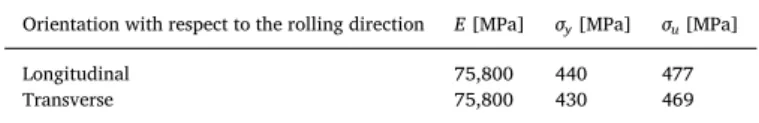
Basic mechanical properties of 2124T851 aluminium alloy,[67].
Orientation with respect to the rolling direction E [MPa] σy[MPa] σu[MPa]
Longitudinal 75,800 440 477
Transverse 75,800 430 469
Fig. 1. Specimen geometries for: (a) push-pull loading (for the Amsler machine, the gripped ends had an M32x1 thread) and torsion loading, (b) plane bending and torsion.
A. Karolczuk, et al. International Journal of Fatigue 134 (2020) 105509
crack initiation. The analysed class is restricted to models with material parameters considered as weights balancing the effect of normal/hy-drostatic and shear/deviatoric stress/strain in the total compounds. Models based on strain energy[53–56]without weighting parameters
are not considered here. Another class of models based on the con-tinuum approach in fatigue modelling is also not considered here. Generally, the class of analysed damage models can be described by the following equation
Table 4
Experimental results (Nexpis in cycles) on smooth specimens from 2124-T851 aluminium alloy obtained under fully reversed push-pull and fully reversed torsion
loading[48].
Push-pullτ σa/a=0 Torsionτ σa/a= ∞ τ σa/a=1 τ σa/a=0.33
σa, [MPa] Nexp τa, [MPa] Nexp σa, [MPa] τa, [MPa] Nexp σa, [MPa] τa, [MPa] Nexp
302 12,974 162 7311 149 148 26,150 252 84 22,773 201 36,415 150 43,400 131 130 52,335 232 77 25,586 239 48,248 139 93,716 119 118 101,175 215 71 51,793 225 63,953 126 103,510 103 102 151,156 190 63 74,238 211 88,930 115 345,686 94 93 338,015 166 55 142,557 201 134,795 103 794,565 83 82 378,806 145 48 231,812 177 205,280 97 1,044,621 81 81 438,345 135 45 431,647 150 485,687 87 2,502,000 75 74 1,323,285 128 43 711,021 143 669,769 81 9,317,040 118 39 2,408,760 137 970,438 137 1,238,210 135 2,313,482
Fig. 2. Photos of fatigue cracks under cyclic bending, torsion and combined bending-torsion loading on 2124T851 Al alloy.
Table 5
Experimental results for 2124-T851 aluminium alloy obtained under fully reversed plane bending and fully reversed torsion loading[48].
Bendingτ σa/a=0 Torsionτ σa/a= ∞ τ σa/a=1 τ σa/a=0.33
σa, [MPa] Nexp τa, [MPa] Nexp σa, [MPa] τa, [MPa] Nexp σa, [MPa] τa, [MPa] Nexp
300 20,846 164 28,110 146 146 48,785 263 87 29,832 300 25,767 155 71,304 138 138 87,335 250 83 39,006 290 26,100 142 94,100 129 129 123,966 238 79 56,598 275 38,304 134 145,908 118 118 142,872 207 69 81,228 275 39,823 144 156,980 111 111 189,126 221 73 83,472 263 57,225 134 216,516 104 104 337,799 190 63 133,399 253 59,556 129 234,168 102 102 406,763 173 57 275,240 269 61,089 112 504,000 96 96 869,526 165 55 425,866 242 81,768 126 608,226 242 85,072 118 699,336 212 115,760 113 706,638 226 140,368 104 1,434,888 200 154,500 104 1,631,190 206 165,768 206 177,336 189 197,656 206 213,264 185 267,776 171 287,200 173 302,856 186 809,464 178 1,083,480 171 2,899,168
Fig. 3. (a) Fatigue characteristics under fully reversed push-pull and torsion loadings identified through the Kohout-Věchet model, also depicting the range of cycles for whichrσ=τ σf/ f, can be set from the interpolated regression curves; and (b) the curve of the fatigue strength ratio rσwithin this range.
Fig. 4. (a) Fatigue characteristics under fully-reversed cyclic torsion and plane bending, identified through the Kohout-Věchet model, and (b) the curve of the fatigue strength ratiorσ=τ σf/ f.
Table 6
Parameters of the Kohout-Věchet model for 2124-T851 aluminium alloy and hollow specimens.
Push-pull Torsion
a, MPa b,– B, cycles C, cycles a0, MPa b0,– B0, cycles C0, cycles
1883.5 −0.196 1110 1,348,908 432.4 −0.105 73 2.58·1014
Table 7
Parameters of the Kohout-Věchet model for 2124-T851 aluminium alloy and hourglass specimens.
Plane bending Torsion
a, MPa b,– B, cycles C , cycles a0, MPa b0,– B0, cycles C0, cycles
13,008,655 −0.974 46,354 109,407 537.2 −0.114 29 1.20·1011
A. Karolczuk, et al. International Journal of Fatigue 134 (2020) 105509
=
F σ M t( ij( , ),ε M tij( , ),K) q N( f), (1)
where F is a function for reducing the cyclically varying multiaxial stress/strain state at point M on the material to a scalar quantity comparable with an adequate value of the reference fatigue curve
q N( f). Depending on the physical quantity applied in Eq.(1), multiaxial models are usually classified as stress-based, strain-based or energy-based [2,57,58]. Constructing the F function, the researchers follow experimental observations of the different influences of the shear/de-viatoric and tensile/hydrostatic components of the stress/strain tensors on the fatigue crack initiation mechanism. As a result of this difference, these components are calculated separately and are related to a scalar quantity by linear or non-linear functions applying the weight factorK. Moreover, the amplitude, the maximum value and the mean value of these components are usuallyfirst computed from the histories of the stress and strain states in M, and they are then introduced into the F
function. This class of multiaxial engineering models is based on the assumption that the calculated amplitudes and the mean values of the stress/strain components in M are representative over the whole fatigue life. The potential cyclic evolution of the material behaviour is not taken into account. This methodology is also supported by experimental observations for polycrystalline materials with evidence of crack nu-cleation in the persistent slip bands caused by the amplitude of the shear/deviatoric component. Nucleated short cracks can then develop up to the macroscopic crack size due to the maximum value of the
tensile/hydrostatic component. The weighting factors are identified by fitting Eq.(1) to the experimental data under uniaxial loading. The material parametersKare not constant for the wide range of numbers of cycles to failure, because the fatigue damage mechanisms depend in general on the magnitude of the applied loading. For higher loading amplitudes, multiple cracks can nucleate followed by the coalescence mechanism. When the loading amplitudes are reduced, the damage becomes a more local process. The variation of theK parameters is reflected in Eq.(1), if it is applied to uniaxial loading. For example, in the stress-based model under uniaxial push-pull loading for various applied stress amplitudes σ Na( f), Eq.(1)takes the form
=
F σ N(a( f),K) q N( f). (2)
TheK parameter is found by solving the above equation, deriving for example the f function as
=
K f σ N( a( f),q N( f)). (3)
If the F function is assumed to be the same over a large interval of numbers of cycles to failure, it is evident that, in general, theK para-meter is a function of the number of cycles to failure. The greater the number of weighting factors in the multiaxial model, the more ex-perimental data items must be provided to identifyK. The same pro-cedure concerns energy-based and strain-based multiaxial damage models.
3. Explicit forms of selected multiaxial fatigue models
The selected well-recognized multiaxial fatigue strength criteria are transformed into a form with life-dependent material parameters. The new forms with physical restrictions assigned to life-dependent material parameters are presented inTable 1. In order to focus only on the question offixed and life-dependent weight factors, the criteria were reformulated to remove any mean stress effect, which could otherwise affect the comparison. The experimental data used later for verification also correspond to fully reversed loadings. For stress-based models, the material parameters are mostly a function of the ratio of torsion fatigue strength to axial fatigue strength r Nσ( f). The form here is universal - it is not restricted to some particular S-N curve descriptions, and thus e.g. the Kohout-Věchet formula[47]can be successfully applied afterwards. Calculating the number of cycles to failureNcal=Nf using the concept of life-dependent material parameters requires the implementation of an iterative procedure.
Fig. 5. The microstructure of the tested 2124T851 alloy in longitudinal cross-section, with the fatigue crack obtained under plane bending.
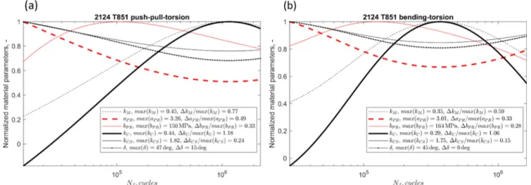
Fig. 6. Normalized material parameters of the selected stress-based models for 2124-T851 aluminium alloy and both sets of experimental data, i.e. (a) under combined push-pull and torsion and (b) under combined bending and torsion loadings.
4. Experiments
Aluminium alloy 2124-T851, which is widely used in aircraft structures, was selected for an evaluation of multiaxial fatigue strength criteria with life-dependent material parameters. Its chemical compo-sition is presented in Table 2, and basic mechanical properties are presented inTable 3.
Two sets of experimental fatigue tests were carried out on smooth specimens cut out along the rolling direction of a plate 38.1 mm in thickness [67]. The final diameters of the specimen were obtained through afine turning process. The stresses were calculated applying the isotropic and elastic material behaviour in the critical cross-section of the specimens, neglecting the stress concentration due to the non-uniform cross-section because the theoretical stress concentration fac-tors were very close to one.
In the first set, the cylindrical hollow specimens (Fig. 1a) were subjected to fully reversed push-pull and torsion loading with various stress ratios until the specimens broke completely or up to the moment
the stiffness decreased by 10%. The tests under load control were conducted using the Schenck (torsion), Inova (combined) and Amsler (push-pull) fatigue machines. The theoretical stress concentration fac-tors were Kt= 1.010 in push-pull and Kt= 1.004 in torsion. The
ex-perimental results are presented inTable 4.
In the second set of experimental tests, hourglass specimens (Fig. 1b, Kt= 1.01 for bending and Kt= 1.01 for torsion) were
sub-jected to fully-reversed plane bending and torsion with various loading ratios. The specimens were tested under force control[68]. Specimen failure was defined as a 20% drop in stiffness under the applied loading. This criterion resulted in relatively long cracks around 5–10 mm in length for bending and for combined loading, and 10–20 mm in length for torsion (along the longitudinal axis of the specimen,Fig. 2). The experimental results are presented inTable 5.
A non-linear relation in the fatigue characteristic is observed under push-pull and plane bending (Figs. 3a and4a). For this reason, the non-linear characteristic proposed by Kohout and Věchet[52]is applied in the following form
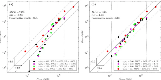
Fig. 7. A comparison of the experimental and calculated numbers of cycles to failure for the Crossland model and 2124-T851 aluminium alloy subjected to combined push-pull and torsion loading: (a) thefixed material parameters; (b) the life-dependent material parameters.
Fig. 8. A comparison of the experimental and calculated numbers of cycles to failure for the Crossland model and 2124-T851 aluminium alloy subjected to combined bending and torsion loading: (a) thefixed material parameters; (b) the life-dependent material parameters.
A. Karolczuk, et al. International Journal of Fatigue 134 (2020) 105509
⎜ ⎟ ⎜ ⎟ = ⎛ ⎝ + + ⎞ ⎠ = ⎛ ⎝ + + ⎞ ⎠
For plane bending σ N a CN B
N C and for torsion
τ N a C N B N C : ( ) , : ( ) f f f f b f f f f b 0 0 0 0 0 (4)
The experimental points and the fatigue characteristics identified using the Kohout-Věchet model are presented inFigs. 3a and4a. The vertical dashed lines inFigs. 3a and4a depict the intersection of the ranges of the experimental fatigue lives of the two S-N curves that are needed to define the material parameters of the individual criteria. This final range thus defines the primary domain of the fatigue life calcu-lation. If the experimental fatigue life is outside this domain, it means that parts of the two inputs into the material parameter were extra-polated. These results are not included in the calculation of the error indicators for the multiaxial fatigue models. Figs. 3b and 4b include graphs depicting the dependency of the fatigue strength ratiorσ=τ σf/ f on the fatigue life Nf. For the given experimental fatigue life regime, the
ratiorσ=τ σf/ f is neither constant nor a monotonic function. It varies between 0.551 at 13,000 cycles and 0.724 at 1100,000 cycles for the hollow specimens (Δrσ=0.17), and between 0.572 at 28,000 cycles and 0.675 at 372,000 cycles (Δrσ=0.10) for the hourglass specimens. The Kohout-Věchet model parameters are presented inTables 6 and 7.
The quality of thefitting of the regression curve and the efficiency of the multiaxial models for the fatigue life calculations were estimated on the basis of percentage error PE:
= − ×
PE logN logN logN 100.
f exp
exp (5)
Statistics of PE provide information about the overall criterion ef-ficiency in fatigue life estimation. Mean value MPE and the standard deviation SD of PE have been evaluated. The values of error indicator
SDcalculated for individual fatigue curves and for all data items in the test set are presented inFigs. 3a and4a. It should be noted that negative values of PE concern cases where the computed life was shorter than the experimental one, i.e. a conservative estimate, while non-conservative
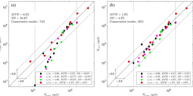
Fig. 9. A comparison of the experimental and calculated numbers of cycles to failure for the Matake model and 2124-T851 aluminium alloy subjected to combined push-pull and torsion loading: (a) thefixed material parameters; (b) the life-dependent material parameters.
Fig. 10. A comparison of the experimental and calculated numbers of cycles to failure for the Matake model and 2124-T851 aluminium alloy subjected to combined bending and torsion loading: (a) thefixed material parameters; (b) the life-dependent material parameters.
(unsafe) estimates are indicated by positive PE values.
The microstructure of the tested 2124T851 alloy is characterised by unequiaxed grains (Fig. 5) with coarse particles of intermetallic phases Al6(Fe, Mn)[69].
Different trends of the SN curves (Figs. 3a and4a) are observed for torsion and axial/bending loadings. The S-N curves for cyclic torsion loading are characterised by nearly linear relation for analysed fatigue life range comparing with the S-N curves for axial and bending load-ings. It is deduced that the existence of the secondary particles of in-termetallic phases and unequiaxed grains are the main reason for the observed behaviour. Under axial/bending loading, the fatigue cracks attracted by the stress concentration in the vicinity of secondary phases propagate inside the specimen. Decreasing the amplitude of loading the number of initiated cracks is dropping (Fig. 2) and the higher fatigue life scatter is observed around 106 cycles. For torsion loading, the
maximum normal stress is much less than under axial loading and the stress concentration due to secondary particles is too low to dominate the failure mechanism. Additionally, the initiated cracks propagate
along the specimen surface in direction of elongated grains (maximum shear stress plane). At last, much smaller volume is loaded by maximum stresses. As a consequence, a single shear mechanism dominates over observed fatigue life range (till 107cycles, Fig. 3a) reflected by the
linear SN curves.
5. Selected fatigue criteria
Four stress-based multiaxial fatigue strength criteria were selected for verifying the form with fixed material parameters and a more flexible form with the life-dependent material parameters. The linear stress reduction functions proposed by Stulen-Cummings-Findley, Dang Van, Matake and Papadopoulos (Table 1) result in the same fatigue life calculation under the applied proportional load path. The results ob-tained by these linear models are therefore merged into a single unit and are presented by the Matake model. The other selected criteria (Table 1), i.e. the Crossland criterion, the Papuga-Růžička criterion, and the Carpinteri-Spagnoli criterion differ significantly in the stress
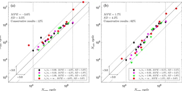
Fig. 11. A comparison of the experimental and calculated numbers of cycles to failure for the Papuga-Růžička model and 2124-T851 aluminium alloy subjected to combined push-pull and torsion loading: (a) thefixed material parameters; (b) the life-dependent material parameters.
Fig. 12. A comparison of the experimental and calculated number of cycles to failure for the Papuga-Růžička model and 2124-T851 aluminium alloy subjected to combined bending and torsion loading: (a) thefixed material parameters; (b) the life-dependent material parameters.
A. Karolczuk, et al. International Journal of Fatigue 134 (2020) 105509
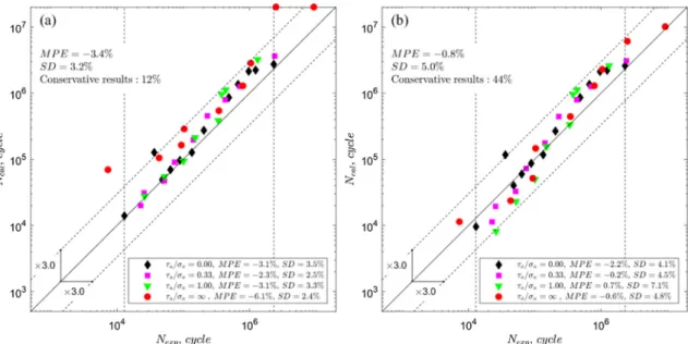
Fig. 13. A comparison of the experimental and calculated number of cycles to failure for the Carpinteri-Spagnoli model and 2124-T851 aluminium alloy subjected to combined push-pull and torsion loading: (a) thefixed material parameters; (b) the life-dependent material parameters.
Fig. 14. A comparison of the experimental and calculated number of cycles to failure for the Carpinteri-Spagnoli model and 2124-T851 aluminium alloy subjected to combined bending and torsion loading: (a) thefixed material parameters; (b) the life-dependent material parameters.
Fig. 15. MPE and SD error indicators calculated with thefixed and life-dependent material parameters for 2124-T851 aluminium alloy under combined push-pull and torsion loading.
reduction function and in the definition of the critical plane.
The Crossland criterion[59]is a stress invariant-based type of fa-tigue model. The equivalent stress is the linear sum of the amplitude of the second invariant of the stress tensor deviator and the weighted value of the maximum hydrostatic stress.
The Matake criterion[63]states that the linear combination of the shear and normal stress amplitudes on the plane of the maximum shear stress range defines the effective shear stress, which is compared with the fatigue limit. Introducing the life-dependent material parameter into the Matake criterion provides a very simple way to extend its ap-plicability to fatigue life calculations.
The third selected criterion, proposed by Papuga and Ruzicka[66], applies the non-linear function of shear and normal stress components on the critical plane (Table 1) of the maximum effective tensile stress. The search for the critical plane of the maximum damage in the defined parabolic function leads to two regions of fatigue strength ratios, in which the weight parameters are defined by different formulas. The smooth transition point between these two intervals is defined at rσ = 0.866.
The fourth criterion, proposed by Carpinteri and Spagnoli[65], also applies the non-linear function of shear and normal stress components on the critical plane. However, in this case the function describes an ellipse with non-constant lengths of the axes when the life-dependent material parameters are applied. The critical plane is related to the weighted mean principal stress directions by an empirical function originally based on the fatigue limits. For life-dependent material parameters, this function is developed to
= −
δ N( ) 45·3 r N
2(1 ( ) ),
f σ f 2 (6)
where δ is the angle, expressed in degrees, by which thefinal fracture plane is assumed to be inclined from the critical plane. The Carpinteri-Spagnoli model includes the material parameterkCS(Table 1), the use of which results in the maximum equivalent stress for in-phase loading only for angleδ=0deg (brittle failure,rσ=1). However, the form of material parameterkCSis widely applied according to the criterion also forδ≠0deg. Angle δ becomes the material parameter due to function
(6).The calculation of the fatigue life with the life-dependent material concept includes an iterative process for solving the equations pre-sented inTable 1. The search for the critical plane was conducted in the three-dimensional space based on three Euler angles with the angular step equal to 1 deg along each direction.
6. Results and discussion
For comparison purposes, the fatigue lives were calculated forfixed material parameters determined at 106 cycles (reference point) to
failure and for life-dependent material parameters. Comparisons of the experimental and calculated fatigue lives are presented inFigs. 7–14.
Variations of life-dependent material parameters kC,kCS,kM,aPR,bPR and δ for each analysed stress-based model along the observed ex-perimental fatigue life domain (S-N curves) are presented inFig. 6. For better visualization, the material parameters have been normalized by the respective maximum values, which are included in the legend of
Fig. 6. It should be noted that parameterkCbecomes negative for the lowest fatigue lives for both evaluated combinations of load cases. However, there are scarcely enough points to show whether this strange behaviour has a negative impact on the estimation quality, so no cor-rective measures were taken to prevent the occurrence of negative values.
The models with a linear relation between the shear/deviatoric and tensile stress components in the scalar function Eq.(2)(the Crossland criterion and the Matake proposal) showed the highest variation of the normalized weight parameter (Fig. 6), when comparing the variation of the material parameters for the non-linear models. Variation of angle δ is observed (Fig. 6) for both sets of experimental data. For combined push-pull and torsion loading, the angle changes within 15°, and for combined bending and torsion loading the angle changes within 9°.
Fig. 7presents a comparison of the calculated and experimental fatigue lives, when the Crossland model is applied for thefixed material parameters (Fig. 7a) and for the life-dependent material parameter (Fig. 7b) for the combined push-pull and torsion data set.Fig. 8shows similarly prepared information for the combined bending and torsion data set. The vertical dashed lines inFigs. 7–14represent the limits of valid comparison. The Crossland and Matake models (Figs. 9 and 10) with thefixed material parameters estimate the fatigue lives correctly only around the reference number of cycles for which rσwas computed.
Figs. 7a,8a,9a and 10a clearly show a growing deviation of the cal-culated lives from the experimental lives with increasing distance from the reference point. There is a remarkable improvement in the fatigue life prediction provided by the Crossland and Matake models with the life-dependent material parameters in comparison with thefixed ap-proach. This is shown by both error indicatorsMPEandSD.
The results of applying the Papuga-Růžička model to fatigue life calculation are presented in Figs. 11 and 12. For the fixed material parameter approach, some data items resulted in equivalent stress below the asymptotic value of the non-linear Kohout-Věchet regression model, which represents the fatigue limit. As a consequence, the pre-dicted fatigue lives would approach infinity for these cases. In the fig-ures presented here, these estimates are located on the upper plot boundary inFigs. 11a and 12b, i.e. at the level of estimated 2·107
cy-cles. For combined push-pull and torsion loading (Fig. 11), the fatigue lives calculated with the life-dependent material parameters are better aligned along the diagonal line of perfect agreement, but with larger scatter (SDvalue) than for thefixed material parameter. The results for combined bending and torsion loading exhibit a similar tendency. However, the scatter of the fatigue lives for the life-dependent material
Fig. 16. MPE and SD error indicators calculated with thefixed and life-dependent material parameters for 2124-T851 aluminium alloy under combined bending and torsion loading.
A. Karolczuk, et al. International Journal of Fatigue 134 (2020) 105509
parameters is lower than for the fixed material parameters. This is mainly due to data (two points) with the equivalent stress below the lower asymptotic stress level of the Kohout-Věchet curve.
The results obtained by applying the Carpinteri-Spagnoli model are presented inFigs. 13 and 14. In general, the Carpinteri-Spagnoli model behaves in a very similar way to the Papuga-Růžička model. The same overestimated fatigue lives can be found for some data items when the fixed material parameters approach is applied.
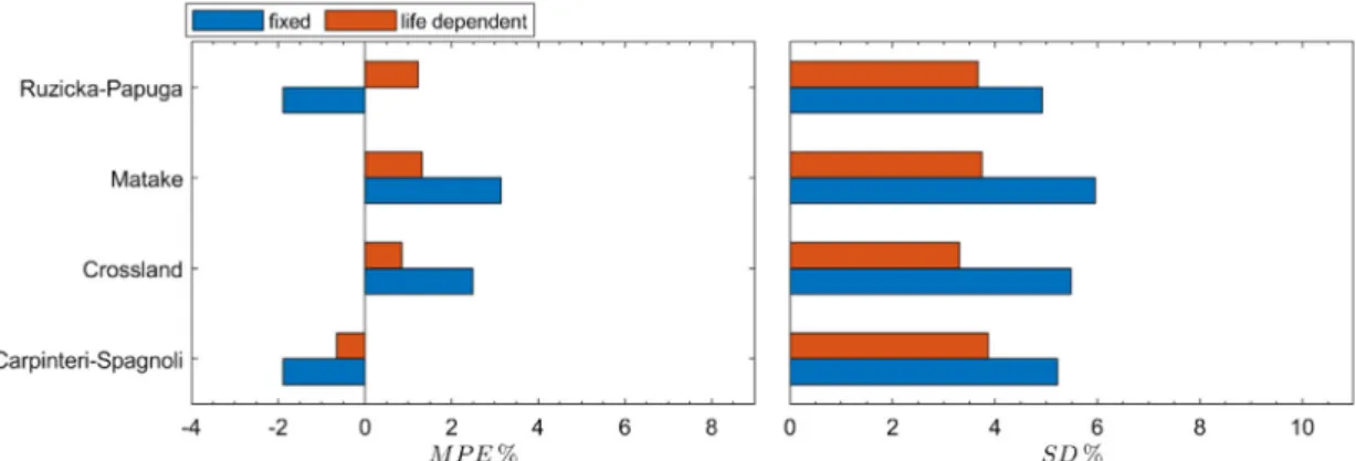
Fig. 15presents bars with theMPEandSDerror indicators obtained under combined push-pull and torsion for all analysed stress-based models.Fig. 16provides the same information under combined bending and torsion loading.
TheMPEerror indicator for all analysed criteria and data sets was reduced by applying the life-dependent material parameters, in com-parison with the approach with thefixed material parameters. A greater improvement in the fatigue life calculation is observed for linear models (the group represented by the Matake criterion and the Crossland cri-terion). The scale of the improvement is clearly related to the much more pronounced change in the weight parameters of these two models within the evaluated range of lifetimes than for the non-linear methods (seeFig. 6).
The closest to zero value of theMPEerror indicator for push-pull-torsion loading (−0.77%) and for bending-torsion loading (−0.65%) were obtained for the Carpinteri-Spagnoli model with the life-depen-dent material parameters. However, the SD value is highest for the Carpinteri-Spagnoli model for combined push-pull and torsion loading. It is observed that all error indicators are considerably equalized for all models where the life-dependent material parameters concept is ap-plied. This is in accordance with Papuga’s comment in[70]that most of the criteria provide estimates of very similar quality for in-phase loading. This conclusion further proves that the use offixed material parameters misbalances the predictive capability of the criteria, and the impact is worst for the linear methods.
TheSDerror indicator was lower for all analysed criteria for the combined bending and torsion data set when the life-dependent mate-rial parameters were used than for the approach with fixed material parameters. However, for the combined push-pull and torsion data set the SD error indicator is slightly higher for the non-linear models (though still acceptable, with only a single point outside the fatigue life scatter band factor 3,Figs. 11b and13b) than when it was computed for the approach with thefixed material parameters. This behaviour cannot be assumed as general, because only two data sets are compared here. For an adequate assessment of the quality of individual proposals, it would be necessary to analyse a much larger number of experiments.
7. Conclusions
•
The quality of the predictions of stress-based multiaxial fatigue criteria with a linear scalar function are substantially affected by any variation in the ratio of shear fatigue strength to axial fatigue strength on smooth specimens.•
Introducing the life-dependent material parameters into the stress-based models using a linear scalar function significantly improves the fatigue life prediction. An acceptable level of convergence be-tween the experimental and calculated fatigue lives for 2124-T851 aluminium alloy under uniaxial and proportional loading paths is reached.•
The Kohout-Věchet non-linear regression model was successfully applied to the concept of life-dependent material parameters.•
The impact of life-dependent material parameters to stress-based multiaxial criteria within the multiaxial fatigue life calculation is strongly dependent on the applied model. The non-linear models evaluated here are less sensitive to this effect.•
The introduction of life-dependent material parameters into the multiaxial fatigue strength criteria extends their applicability over a wide range of fatigue lives in a relatively simple way for engineeringapplications. This could have an immense impact on the correct assessment of damage under variable amplitude loadings that are representative of real loadings applied on components.
Declaration of Competing Interest
The authors declare that they have no known competingfinancial interests or personal relationships that could have appeared to influ-ence the work reported in this paper.
Acknowledgements
This study wasfinanced by the National Science Centre, Poland (Decision No. 2017/25/B/ST8/00684). Jan Papuga acknowledges support from ESIF, EU Operational Programme Research, Development and Education, and from the Center of Advanced Aerospace Technology (CZ.02.1.01/0.0/0.0/16_019/0000826), Faculty of Mechanical Engineering, Czech Technical University in Prague.
References
[1] Schütz W. A history of fatigue. Eng Fract Mech 1996;54:263–300.
[2] Karolczuk A, Macha E. A review of critical plane orientations in multiaxial fatigue failure criteria of metallic materials. Int J Fract 2005;134:267–304.https://doi.org/ 10.1007/s10704-005-1088-2.
[3] Mroziński S. Energy-based method of fatigue damage cumulation. Int J Fatigue 2019;121:73–83.https://doi.org/10.1016/j.ijfatigue.2018.12.008.
[4] Zhu SP, Yu ZY, Correia J, De Jesus A, Berto F, De Jesus A, et al. Evaluation and comparison of critical plane criteria for multiaxial fatigue analysis of ductile and brittle materials. Int J Fatigue 2018;112:279–88.https://doi.org/10.1016/j. ijfatigue.2018.03.028.
[5] Vu QH, Halm D, Nadot Y. Multiaxial fatigue criterion for complex loading based on stress invariants. Int J Fatigue 2010;32:1004–14.https://doi.org/10.1016/j. ijfatigue.2009.11.006.
[6] Kamal M, Rahman MM. Advances in fatigue life modeling: a review. Renew Sustain Energy Rev 2018;82:940–9.https://doi.org/10.1016/j.rser.2017.09.047. [7] Kenmeugne B, Soh Fotsing BD, Anago GF, Fogue M, Robert JL, Kenne JP. On the
evolution and comparison of multiaxial fatigue criteria. Int J Eng Technol 2012;4:37–46.
[8] Zhu S-P, Yu Z-Y, Liu Q, Ince A. Strain energy-based multiaxial fatigue life prediction under normal/shear stress interaction. Int J Damage Mech 2019;28:708–39.
https://doi.org/10.1177/1056789518786031.
[9] Feng ES, Wang XG, Jiang C. A new multiaxial fatigue model for life prediction based on energy dissipation evaluation. Int J Fatigue 2019;122:1–8.https://doi.org/10. 1016/j.ijfatigue.2019.01.003.
[10] Lu C, Melendez J, Martínez-Esnaola JM. A universally applicable multiaxial fatigue criterion in 2D cyclic loading. Int J Fatigue 2018.https://doi.org/10.1016/j. ijfatigue.2018.01.013.
[11] Springer M, Pettermann HE. Fatigue life predictions of metal structures based on a low-cycle, multiaxial fatigue damage model. Int J Fatigue 2018;116:355–65.
https://doi.org/10.1016/j.ijfatigue.2018.06.031.
[12] Mamiya EN, Castro FC, Malcher L, Araújo JA. Multiaxial fatigue life estimation based on combined deviatoric strain amplitudes. Int J Fatigue 2014;67:117–22.
https://doi.org/10.1016/j.ijfatigue.2013.11.002.
[13] Matsubara G, Nishio K. Multiaxial high-cycle fatigue criterion for notches and su-perficial small holes from considerations of crack initiation and non-propagation. Int J Fatigue 2014;67:28–37.https://doi.org/10.1016/j.ijfatigue.2014.02.009. [14] Arora P, Gupta SK, Samal MK, Chattopadhyay J. Development of new critical plane
model for assessment of fatigue life under multi-axial loading conditions. Int J Fatigue 2019;105209.https://doi.org/10.1016/j.ijfatigue.2019.105209. [15] Suman S, Kallmeyer A, Smith J. Development of a multiaxial fatigue damage
parameter and life prediction methodology for non-proportional loading. Frat Ed Integrita Strutt 2016;10:224–30.https://doi.org/10.3221/IGF-ESIS.38.30. [16] Matsubara G, Hayashida A, Kano D. Predicting the multiaxial fatigue limit and the
multiaxial high-cycle fatigue life based on the unified equivalent shear stress from axial strength characteristics with various waveforms. Int J Fatigue
2018;112:52–62.https://doi.org/10.1016/j.ijfatigue.2017.12.001.
[17] Braccesi C, Morettini G, Cianetti F, Palmieri M. Development of a new simple en-ergy method for life prediction in multiaxial fatigue. Int J Fatigue 2018;112:1–8.
https://doi.org/10.1016/j.ijfatigue.2018.03.003.
[18] Lu C, Melendez J, Martínez-Esnaola JM. Multiaxial fatigue criterion considering the influence of out-of-phase failure and loading condition. Int J Fatigue
2018;114:323–30.https://doi.org/10.1016/j.ijfatigue.2018.06.006. [19] Gao D, Yao W, Wu T. A damage model based on the critical plane to estimate
fatigue life under multi-axial random loading. Int J Fatigue 2018.https://doi.org/ 10.1016/j.ijfatigue.2018.06.025.
[20] Lu C, Melendez J, Martínez-Esnaola JM. Modelling multiaxial fatigue with a new combination of critical plane definition and energy-based criterion. Int J Fatigue 2018;108:109–15.https://doi.org/10.1016/j.ijfatigue.2017.12.004.
[21] Cruces AS, López-Crespo P, Moreno B, Antunes FV. Multiaxial fatigue life prediction on S355 structural and offshore steel using the SKS critical plane model. Metals (Basel) 2018;8:1–12.https://doi.org/10.3390/met8121060.
[22] Zhu H, Wu H, Lu Y, Zhong Z. A novel energy-based equivalent damage parameter for multiaxial fatigue life prediction. Int J Fatigue 2019;121:1–8.https://doi.org/ 10.1016/j.ijfatigue.2018.11.025.
[23] Carpinteri A, Vantadori S, Lagoda T, Karolczuk A, Kurek M, Ronchei C. Fatigue assessment of metallic components under uniaxial and multiaxial variable ampli-tude loading. Fatigue Fract Eng Mater Struct 2018;41:1306–17.https://doi.org/10. 1111/ffe.12773.
[24] Socie DF. Critical plane approaches for multiaxial fatigue damage assessment. Am Soc Test Mater 1993; ASTM STP 1:7–36.
[25] Forrest PG. Fatigue of metals. Pergamon Press; 1962.
[26] Fatemi A, Socie DF. A critical plane approach to multiaxial fatigue damage in-cluding out-of-phase loading. Fatigue Fract Eng Mater Struct 1988;11:149–65.
https://doi.org/10.1111/j.1460-2695.1988.tb01169.x.
[27] Marquis G, Socie DF. Long-life torsion fatigue with normal mean stresses. Fatigue Fract Eng Mater Struct 2000;23:293–300.https://doi.org/10.1046/j.1460-2695. 2000.00291.x.
[28] Xue Y, El Kadiri H, Horstemeyer MF, Jordon JB, Weiland H. Micromechanisms of multistage fatigue crack growth in a high-strength aluminum alloy. Acta Mater 2007;55:1975–84.https://doi.org/10.1016/j.actamat.2006.11.009.
[29] Vojtek T, Pokluda J, Hohenwarter A, Pippan R. Progress in understanding of in-trinsic resistance to shear-mode fatigue crack growth in metallic materials. Int J Fatigue 2015;89:36–42.https://doi.org/10.1016/j.ijfatigue.2016.01.009. [30] Vojtek T, Hohenwarter A, Pippan R, Pokluda J. Experimental evidence of a common
local mode II growth mechanism of fatigue cracks loaded in modes II, III and II + III in niobium and titanium. Int J Fatigue 2016;92:470–7.https://doi.org/10.1016/j. ijfatigue.2016.02.042.
[31] Karolczuk A, Kluger K,Łagoda T. A correction in the algorithm of fatigue life cal-culation based on the critical plane approach. Int J Fatigue 2016;83:174–83.
https://doi.org/10.1016/j.ijfatigue.2015.10.011.
[32] Karolczuk A. Analysis of revised fatigue life calculation algorithm under propor-tional and non-proporpropor-tional loading with constant amplitude. Int J Fatigue 2016;88:111–20.https://doi.org/10.1016/j.ijfatigue.2016.03.027. [33] Karolczuk A, Skibicki D, PejkowskiŁ. Evaluation of the Fatemi-Socie damage
parameter for the fatigue life calculation with application of the Chaboche plasticity model. Fatigue Fract Eng Mater Struct 2019;42:197–208.https://doi.org/10.1111/ ffe.12895.
[34] Findley WN, Coleman JJ, Hanley BC. Theory for combined bending and torsion fatigue with data for SAE 4340 steel. Proc. Int. Fatigue Met. London: Institute of Mechanical Engineers; 1956. p. 150–7.
[35] Svärd H. A branch and bound algorithm for evaluation of the Findley fatigue cri-terion. Int J Fatigue 2015;73:27–38.https://doi.org/10.1016/j.ijfatigue.2014.11. 008.
[36] Sahadi JV, Paynter RJH, Nowell D, Pattison SJ, Fox N. Comparison of multiaxial fatigue parameters using biaxial tests of Waspaloy. Int J Fatigue 2017;100:477–88.
https://doi.org/10.1016/j.ijfatigue.2017.01.019.
[37] Reis L, Li B, de Freitas M. Crack initiation and growth path under multiaxial fatigue loading in structural steels. Int J Fatigue 2009;31:1660–8.https://doi.org/10. 1016/j.ijfatigue.2009.01.013.
[38] Li J, Zhang Z, Sun Q, Li C. Multiaxial fatigue life prediction for various metallic materials based on the critical plane approach. Int J Fatigue 2011;33:90–101.
https://doi.org/10.1016/j.ijfatigue.2010.07.003.
[39] McClaflin D, Fatemi A. Torsional deformation and fatigue of hardened steel in-cluding mean stress and stress gradient effects. Int J Fatigue 2004;26:773–84.
https://doi.org/10.1016/j.ijfatigue.2003.10.019.
[40] Fatemi A, Kurath P. Multiaxial fatigue life predictions under the influance of mean-stresses. Trans ASME J Eng Technol 1988;110:380–8.
[41] Shamsaei N, Fatemi A. Effect of hardness on multiaxial fatigue behaviour and some simple approximations for steels. Fatigue Fract Eng Mater Struct 2009;32:631–46.
https://doi.org/10.1111/j.1460-2695.2009.01369.x.
[42] Lopez-crespo P, Moreno B, Lopez-moreno A, Zapatero J. Study of crack orientation and fatigue life prediction in biaxial fatigue with critical plane models. Eng Fract Mech 2015;136:115–30.https://doi.org/10.1016/j.engfracmech.2015.01.020. [43] Xu S, Zhu S-P, Hao Y-Z, Liao D. Critical plane–based multiaxial fatigue life
pre-diction of turbine disk alloys by refining normal stress sensitivity. J Strain Anal Eng Des 2018;53:719–29.https://doi.org/10.1177/0309324718779922.
[44] Anes V, Caxias J, Freitas M, Reis L. Fatigue damage assessment under random and variable amplitude multiaxial loading conditions in structural steels. Int J Fatigue 2017;100:591–601.https://doi.org/10.1016/j.ijfatigue.2016.12.009.
[45] Carpinteri A, Spagnoli A, Vantadori S, Bagni C. Structural integrity assessment of metallic components under multiaxial fatigue: The C-S criterion and its evolution.
Fatigue Fract Eng Mater Struct 2013;36:870–83.https://doi.org/10.1111/ffe. 12037.
[46] Carpinteri A, Berto F, Campagnolo A, Fortese G, Ronchei C, Scorza D, et al. Fatigue assessment of notched specimens by means of a critical plane-based criterion and energy concepts. Theor Appl Fract Mech 2016;84:57–63.https://doi.org/10.1016/ j.tafmec.2016.03.003.
[47] Carpinteri A, Ronchei C, Scorza D, Vantadori S. Fatigue life estimation for multi-axial low-cycle fatigue regime: the influence of the effective Poisson ratio value. Theor Appl Fract Mech 2015;79:77–83.https://doi.org/10.1016/j.tafmec.2015.06. 013.
[48] Slámečka K, Pokluda J, Kianicová M, Horníková J, Obrtlík K. Fatigue life of cast Inconel 713LC with/without protective diffusion coating under bending, torsion and their combination. Eng Fract Mech 2013;110:459–67.https://doi.org/10. 1016/j.engfracmech.2013.01.001.
[49] Kluger K, Lagoda T. A new algorithm for estimating fatigue life under mean value of stress. Fatigue Fract Eng Mater Struct 2017;40:448–59.https://doi.org/10.1111/ ffe.12515.
[50] Araújo JA, Carpinteri A, Ronchei C, Spagnoli A, Vantadori S. An alternative defi-nition of the shear stress amplitude based on the Maximum Rectangular Hull method and application to the C-S (Carpinteri-Spagnoli) criterion. Fatigue Fract Eng Mater Struct 2014;37:764–71.https://doi.org/10.1111/ffe.12180.
[51] Araújo JA, Dantas AP, Castro FC, Mamiya EN, Ferreira JLA. On the characterization of the critical plane with a simple and fast alternative measure of the shear stress amplitude in multiaxial fatigue 2011;33:1092–100. doi:10.1016/j.ijfatigue.2011. 01.002.
[52] Kohout J, Vechet S. A new function for fatigue curves characterization and its multiple merits. Int J Fatigue 2001;23:175–83.https://doi.org/10.1016/j.ijfatigue. 2005.07.023.
[53] Saintier N, Palin-Luc T, Bénabes J, Cocheteux F. Non-local energy based fatigue life calculation method under multiaxial variable amplitude loadings. Int J Fatigue 2013;54:68–83.https://doi.org/10.1016/j.ijfatigue.2012.12.013.
[54] Delahay T, Palin-Luc T. Estimation of the fatigue strength distribution in high-cycle multiaxial fatigue taking into account the stress-strain gradient effect. Int J Fatigue 2006;28:474–84.https://doi.org/10.1016/j.ijfatigue.2005.06.048.
[55] Golos K, Ellyin F. Total strain energy density as a fatigue damage parameter. In: Branco CM, Rosa LG, editors. Adv. Fatigue Sci. Technol. Dordrecht: Springer Netherlands; 1989. p. 849–58.https://doi.org/10.1007/978-94-009-2277-8_42. [56] Garud YS. A new approach to the evaluation of fatigue under multiaxial loadings. J
Eng Mater Technol 1981;103:118–25.
[57] Ellyin F. Fatigue failure under multiaxial states of stress. Fatigue damage, crack growth life predict. Dordrecht: Springer; 1997. p. 484.
[58] Macha E, Sonsino CM. Energy criteria of multiaxial fatigue failure. Fatigue Fract Eng Mater Struct 1999;22:1053–70.https://doi.org/10.1046/j.1460-2695.1999. 00220.x.
[59] Crossland B. Effect of large hydrostatic pressures on the torsional fatigue strength of an alloy steel. Proc. Int. Conf. Fatigue Met. London: Institute of Mechanical Engineers; 1956. p. 138–49.
[60] Stulen FB, Cummings HN. A failure criterion for multiaxial fatigue stresses. Proc ASTM 1954;54:822–35.
[61] Findley WN. A theory for the effect of mean stress on fatigue of metals under combined torsion and axial load or bending. J Eng Ind 1959:301–6.
[62] Dang Van K, Cailletaud G, Flavenot JF, Le Douaron A, Lieurade HP. Criterion for high cycle fatigue failure under multiaxial loading. London: Mech Eng Publ; 1989. p. 459–78.
[63] Matake T. An explanation on fatigue limit under combined stress. Bull JSME 1977;20:257–63.https://doi.org/10.1299/jsme1958.20.257.
[64] Papadopoulos IV, Ioannis VP. Long life fatigue under multiaxial loading. Int J Fatigue 2001;23:839–49.https://doi.org/10.1016/S0142-1123(01)00059-7. [65] Carpinteri A, Spagnoli A. Multiaxial high-cycle fatigue criterion for hard metals. Int
J Fatigue 2001;23:135–45.https://doi.org/10.1016/S0142-1123(00)00075-X. [66] Papuga J, Ruzicka M. Two new multiaxial criteria for high cycle fatigue
compu-tation. Int J Fatigue 2008;30:58–66.https://doi.org/10.1016/j.ijfatigue.2007.02. 015.
[67] Papuga J, Fojtík F, Vargas M, Hodr A, Karolczuk A, Fusek M, et al. Summary of experiments on 2124-T851 realized within FADOFF project; 2014.
[68] Karolczuk A, Kurek M,Łagoda T. Fatigue life of aluminium alloy 6082 T6 under constant and variable amplitude bending with torsion. J Theor Appl Mech 2015;53:421–30.https://doi.org/10.15632/jtam-pl.53.2.421.
[69] Hao H, Ye D, Chen C. Strain ratio effects on low-cycle fatigue behavior and de-formation microstructure of 2124–T851 aluminum alloy. Mater Sci Eng A 2014;605:151–9.https://doi.org/10.1016/j.msea.2014.03.040.
[70] Papuga J. A survey on evaluating the fatigue limit under multiaxial loading. Int J Fatigue 2011;33:153–65.https://doi.org/10.1016/j.ijfatigue.2010.08.001.
A. Karolczuk, et al. International Journal of Fatigue 134 (2020) 105509