Science Arts & Métiers (SAM)
is an open access repository that collects the work of Arts et Métiers Institute of Technology researchers and makes it freely available over the web where possible.
This is an author-deposited version published in: https://sam.ensam.eu Handle ID: .http://hdl.handle.net/10985/10052
To cite this version :
Tarek BRAHAM-BOUCHNAK, Guénaël GERMAIN, Anne MOREL, Benoit FURET - Influence of high pressure coolant assistance on the machinability of the titanium alloy Ti555-3 - Machining Science and Technology: An International Journal - Vol. 19, n°1, p.134-151 - 2015
Any correspondence concerning this service should be sent to the repository Administrator : archiveouverte@ensam.eu
Corresponding Author: guenael.germain@ensam.eu ; Phone : (+33) 241 207 343 ; Fax number : (+33) 241 207 320 ; Full postal address: Arts et Métiers ParisTech, LAMPA-EA1427, 2, Bd de Ronc
INFLUENCE OF HIGH PRESSURE COOLANT ASSISTANCE ON
THE MACHINABILITY OF THE TITANIUM ALLOY TI555 -3
(Influence of HPC on the machinability of Ti555-3)
T. Braham-Bouchnaka, G. Germaina, A. Morela, B. Furetb
a
Arts et Métiers ParisTech, LAMPA-EA1427, 2, bd de Ronceray 49000 Angers, France
b
IUT Nantes, IRCCyN, 2 avenue du Professeur Jean Rouxel 44475 Carquefou, France
ABSTRACT
The originality of this paper is the quantification of productivity gains and the improvement in surface integrity seen for a recent titanium alloy that is seeing increasing use in the aeronautical industry. The Ti555-3 titanium alloy, which is starting to find greater application in the
aeronautical field, exhibits certain difficulties in terms of machining. High Pressure Coolant (HPC) assisted turning consists of projecting a high pressure coolant jet between the chip and the tool. Comparisons are made between assisted turning using variable jet pressure and conventional turning (dry and classical lubrication). It is shown that it is possible to improve productivity by using HPC assisted machining. The results highlight good chip fragmentation and a great improvement of tool life with HPC assistance. Surface integrity is also shown to be improved, through surface roughness parameters which decrease, and surface residual stresses which
become more compressive. These effects have been attributed to the thermo-mechanical action of
the coolant jet resulting in lower cutting forces, lower coefficient of friction and lower temperature in the cutting zone.
KEYWORDS: High Pressure Coolant; Machinability; Titanium alloys; Surface integrity; Tool life; Cutting Force.
1. INTRODUCTION
To improve the performance of aircraft components, new materials with high strength to weight ratios are sought out and developed. These materials result in a reduction of mass and by
consequence greater fuel efficiency of the final product. Among these materials, titanium alloys are commonly used and in particular the new titanium alloy Ti555-3 is seeing much greater interest. This alloy possesses better mechanical properties compared to the Ti6Al4V alloy. But the difficulties associated with the machining of titanium alloys are well known in the industry (Krämer et al., 2012) and are related in the literature to their mechanical, chemical and thermal properties (Ezugwu and Wang, 1997). These materials have low thermal conductivity, which limits heat transfer and causes strong localization of the cutting temperature in the zone at the tool tip. Moreover they retain high hardness and resistance at high temperatures (up to 800°C). As a result the cutting tool is subjected to high stresses and high temperature. In these conditions, titanium alloys also exhibit a high chemical affinity with most components used in the surface treatment of cutting tools, leading to rapid tool wear (Komanduri and Von Turkovich, 1981). Arrazola et al. (2009) and Nouari et al. (2013) compared the machinability of the Ti555-3 and Ti6Al4V alloys and showed that the machinability of Ti555-3 is even lower than that of Ti6Al4V. Wagner et al. (2011) and Khanna et al. (2013) obtained the same results by studying more specifically the tool wear.
One avenue for improving the machinability of these materials is therefore to promote heat removal (Abdel-Aal et al., 2009). Two investigation paths can be followed. The first is cryogenic assisted machining which has been proved on a Ti6Al4V alloy, to decrease the tool wear
(Venugopal et al., 2007). Dhananchezian et al. ( 2011) measured with this assistance on the same alloy a decrease of the cutting force (35-42%) and of the flank wear (27-39%). A second possible way is the use of a high pressure coolant assistance. Recent studies showed that this assistance offers better tool life (Nandy and Paul, 2008) and chip breakage (Bermingham et al., 2012) than the cryogenic one on a Ti6Al4V alloy. However to the authors’ knowledge there are no
publications concerning the effects of high pressure coolant assistance in the machining of the Ti555-3 titanium alloy.
The current investigation precisely focuses on High Pressure Coolant (HPC) assisted turning of the Ti555-3 alloy. Since machining leaves a residual stress gradient on the surface of the
workpiece that influences the fatigue, fracture and corrosion behavior of the final machined part, it is necessary to know the residual stresses gradient after machining. So the effects of HPC in terms of chip morphology, cutting forces, tool wear and above all surface integrity of the workpiece will be analyzed and discussed.
2. EXPERIMENTAL
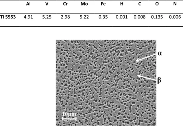
This investigation focus on the Ti555-3 titanium alloy with a hardness of 354 ± 12 Hv whose chemical composition is presented in Table 1. The Ti555-3 alloy consists of a β phase matrix with a body-centred cubic structure and α phase particles in the form of nodules, ranging in size from about 1 to 5 µm (Figure 1).
Al V Cr Mo Fe H C O N Ti 5553 4.91 5.25 2.98 5.22 0.35 0.001 0.008 0.135 0.006
Figure 1: Microstructure of the Ti555-3 titanium alloy investigated.
Turning experiments were carried out on a RAMO lathe. Machining was conducted under dry, classical lubrication and high-pressure coolant environment (5, 10, 20, 30 MPa). Under classical lubrication, overhead flood cooling was undertaken at a flow rate of 30 l/min using the standard coolant delivery system fitted with the lathe. Under classical lubrication and high-pressure coolant environment, the lubricant used was a chemical-based water soluble oil (5% Ecocool, Flush). A Hammelmann HDP 42 high pressure pump supplied room temperature coolant with a maximum flow rate of 42 liters per min and a maximum pressure of 48 MPa. The tool holder has been specifically designed by Sandvik Coromant. It is directly fixed to a “Kistler 9257B”
angled at 15° to the tool holder (Figure 2). The jet pressure and flow rate were measured using a manometer fixed on the tool holder and a digital flowmeter.
Figure 2: High pressure coolant nozzle – geometrical characteristics.
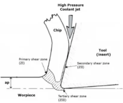
Previous work shows that this configuration enables to fit the coolant between the chip and the tool so that it modifies the contact in the secondary shear zone (Habak and Lebrun, 2011). Figure 3 sketches the high pressure coolant jet in the cutting area. Position of the different shear zones is also defined.
Figure 3: Sketch of the cutting area with high pressure coolant jet.
All tests were performed with carbide inserts of type S05F DNMG 15 06 08 from Sandvik ®. The tool cutting edge angle has a value of 95°. The tool inserts were changed in each test so that the results are not affected by wear. Various combinations of cutting parameters were
investigated (cutting speed Vc ranging from 20 to 90 m.min-1, feed f ranging from 0.1 to 0.3 mm/rev, and depth of cut ap ranging from 0.2 to 1 mm).
SE C
SE C
The lathe was fitted with a Kistler® dynamometer for measuring the three components of the cutting force. These measurements were conducted for each test as well as the surface roughness. The machined chips were also collected and analyzed after each cut. For certain tests, tool wear was investigated as mentioned in ISO 3685 Standard (1993) for tool life testing, and the residual stresses were analyzed, by the x-ray diffraction technique. To analyze the residual stress fields in the workpiece after machining, a PROTO portable X-ray diffractometer was used to determine the diffraction peaks and automatically process the results. The system is based on the sin²ψ method. The principle is to use the variation of the atomic spacing as strain gauge (François et al., 1996). The parameters associated with the residual stress analyses done in this work are presented in Table 2.
Table 2: X-ray diffraction parameters for the Ti555-3 alloy.
Bragg angle Diffraction plane Radiation Collimator diameter
139.6° [213] CuKα 2 mm
The stresses are determined in the axial and circumferential directions of the workpiece. The uncertainty of each measurement point is estimated to be +/- 50 MPa. The analysis of the residual stress evolution as a function of depth was conducted by electrochemically removing a layer of material between each measurement. The stress profiles are analyzed in conjunction with the diffraction peak widths. These values give an indication of the level of strain hardening of the workpiece.
3. INFLUENCE OF HIGH PRESSURE COOLANT ON CHIP MORPHOLOGY In order to investigate the influence of pressure coolant on chip morphology, the machining were carried out under dry, classical lubrication and high-pressure water soluble oil environment (5, 10, 20, 30 MPa). All other process parameters were kept constant (Vc = 50 m/min, f = 0.15 mm/rev, ap = 0.5 mm, and length of cut L = 20 mm). As length of cut is quite small and tool inserts are changed in each test, the wear of the tool is not significant on chip morphology. Figure 4 shows the influence of the jet pressure on chip fragmentation. The chips have been classified according to ISO 3685 Standard (1993). When machining under dry conditions or with classical lubrication, long cylindrical helical chips are produced. Chips are fragmented at a pressure of 5 MPa but the length of the chip is too large (approx. 100 mm) for efficient removal. The chips are well fragmented for jet pressures greater than 10 MPa. Their length decreases with increasing pressure.
Moreover, at a pressure of 30 MPa, the chips become so thin (approx. 3 mm), that it could be harmful to the lathe by becoming wedged into its various elements (slider, spindle, etc). For a pressure of 20 MPa, good chip fragmentation is achieved. With high pressure, the chip wraps up (forming small arcs) and quickly breaks (López De Lacalle et al., 2000). This process occurs faster when the pressure is higher. This observation has also been made by several authors on a nickel alloy (Courbon et al., 2009) and on a Ti6Al4V titanium alloy (Nandy and Paul, 2008; Palanisamy et al., 2009). The jet physically breaks the chip segment (Bermingham et al., 2012).
Figure 4: Macro-photographs of the chips produced during turning of Ti555-3 alloy as a function of coolant pressure (Vc = 50 m/min, f = 0.15 mm/rev, ap = 0.5 mm).
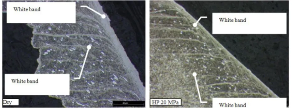
Micrographs of the chips obtained under dry conditions and with high coolant pressure jet (20 MPa) are presented on Figure 5. This alloy has the peculiarity of forming white bands in both the primary and secondary shear zones. These layers are so called “white” because they are very hard and resistant to standard etchants used in metallographic studies. These white-etching layers are not observed in the Ti6Al4V alloy (Sun et al., 2009). But they are noticed in the literature in the hard turning of steel (Ramesh et al., 2005). The common agreement, based on TEM observations (Barry and Byrne., 2002), lies in the fact that they are composed of very fine grains. The
occurrence of phase transformation is discussed. The bands appear due to a strong rise in temperature and / or intense localized plastic deformation. The thickness of the white bands is approximately 4 µm in the primary shear zone for the two configurations (dry machining and HPC with 20 MPa). However, in the secondary shear zone the thickness of the white bands is approximately 15 µm in dry machining and around 5 µm of the HPC configuration. Palanisamy et al. (2009) show on a Ti6Al4V alloy that the shear band thickness increases in the secondary SE
shear zone with increasing coolant pressure for the same cutting conditions. Their results are consistent with this study. Indeed, if the tendency for shear localization is lower with high pressure coolant, the white-etching layers are less likely to form. The high pressure coolant acts directly between the chip and the tool (i.e. on the secondary shear zone) and effectively cools this zone. In contrast, the white bands created in the primary shear zone are similar, with and without assistance, as observed by Machado et al. (1998). These findings indicate that the action of the coolant jet mainly influence the secondary shear zone and has a very limited effect on the primary shear zone.
Figure 5: Influence of jet pressure on the appearance of white bands in Ti555-3 chips with or without high pressure assistance (Vc = 50 m/min, f = 0.15 mm/rev, ap = 0.5 mm).
4. INFLUENCE OF HIGH PRESSURE COOLANT ON THE CUTTING FORCES The tests are based on Tool-Material Pair (AFNOR Norm NF E66-520, 2008) to determine the evolution of the specific cutting force (i.e. the ratio of the cutting force to the area of the
undeformed chip) in conventional lubrication and high pressure coolant assisted tests. The cutting speed has been increased from 20 to 90 m/min in increments of 10 m/min. The feed f is fixed at 0.15 mm/rev and the depth of cut ap at 0.5 mm. For each test, the three components of the cutting force were measured during machining by means of a Kistler® dynamometer. As the three
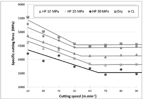
components of the cutting force have similar evolutions, only the tangential cutting force will be discussed below. The results are shown in Figure 6.
The general shape of the curves correspond to the classic behavior for which the specific cutting force decreases with increasing cutting speed, then stabilizes at the cutting speed referred to as
Vcmin.
Figure 6: Specific cutting force as a function of the cutting speed and environment (Dry, Classical Lubricant, and HPC) for ap = 0.5 mm and f = 0.15 mm/rev.
These curves allow the minimum speed cutting, Vcmin, to be determined for the different cutting configurations. Vcmin tends to increase slightly with increasing jet pressure: Vcmin is 50 m/min for the Conventional Lubricant test and 65 m/min for the High Pressure assisted test (30 MPa). Figure 6 also shows that the specific cutting force decreases with increasing coolant pressure. Indeed, for a feed of 0.15 mm/rev and a cutting depth of 0.5 mm, the decrease is about 23% between conventional lubricant and with a pressure of 30 MPa. This reduction is effectively
independent of the cutting speed. High pressure water jet assistance can thus decrease the cutting force, as observed by Nandy et al. (2009) on a Ti6Al4V alloy
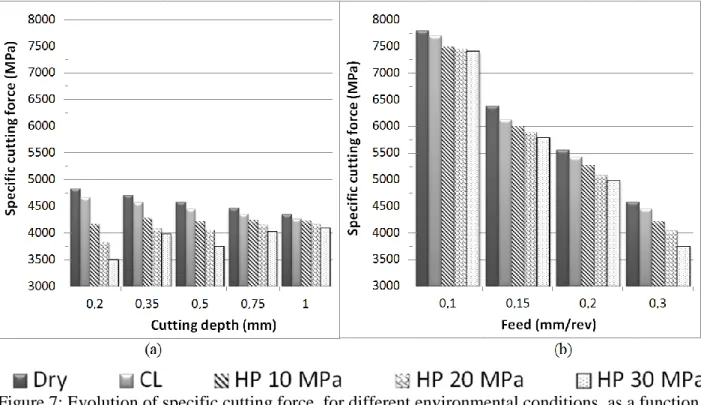
Additional tests at constant cutting speed (Vc = 50 m/min) were conducted to show the influence of high pressure as a function of feed and cutting depth (Figure 7). These tests were done in different configurations with a cutting depth ranging from 0.2 mm to 1 mm, a feed ranging from 0.1 mm/rev to 0.3 mm/rev and 5 environmental configurations (Dry, Conventional Lubricant, High Pressure: 10 MPa, 20 MPa and 30 MPa).
These tests showed that the specific cutting force tends to decrease with the increase in feed and cutting depth (Figure 7). In addition, for all configurations, increasing the jet pressure decreases the specific cutting force (and hence the cutting force). Figure 7 also shows that the decrease in specific cutting force is greater for small cutting depths and for high feeds.
Figure 7: Evolution of specific cutting force, for different environmental conditions, as a function of (a) the cutting depth for a feed f = 0.3 mm/rev and (b) the feed for a depth of cut, ap = 0.5 mm.
Indeed, for high feeds, the decrease in the specific cutting force, KCT, is up to 20% (f =
0.3 mm/rev) depending on the different lubrication configurations. For low feeds, there is only a small effect, 5% (f = 0.1 mm/rev). This can easily be explained, because when the feed is
increased the chip width increases, presenting a larger surface to the action of the jet, while its thickness (which is related to the cutting depth) remains low. Hence, HPC assistance is more efficient for high feeds.
Similarly, the influence of the coolant jet pressure as a function of the cutting depth changes significantly. When the cutting depth is large (1 mm), the jet is less efficient than for low cutting depths. For a cutting depth of 0.2 mm, the high pressure jet decreases the specific cutting force by 29% while for 1 mm cutting depth, this decrease is only 6%. This can also be easily explained by the fact that increasing the cutting depth increases the chip thickness. Hence, they are more resistant to fragmentation. Furthermore, an increase of cutting depth does not significantly change the surface area exposed to the action of the coolant jet.
From these tests, it can be concluded that the type of lubrication (Dry, Classical Lubrication, or High Pressure) significantly influences the cutting forces. The decrease in cutting force with HP assistance is greater when the pressure is high. Furthermore, the effectiveness of HPC assistance is greater when the cutting depth is small and when the feed HPC is high. These trends have similarly been noted by Ezugwu et al. (1997) on titanium alloys, and for the machining of Inconel 718 with high pressure water jet assistance (20 MPa with a feed rate of 0.2 mm/rev) (Ezugwu et al., 2003).
From measurements of cutting force components, the calculation of the apparent coefficient of friction μ can be done using the equation from the theory of Merchant (1945): (eq.1) where Fn and Ft are the normal and tangential cutting forces in the measurement coordinate system and γ is the rake angle. Figure 8 shows this apparent coefficient of friction as a function of the cutting speed and the coolant pressure. The apparent coefficient of friction decreases with increasing coolant pressure. The coolant jet directed between the tool and the chip facilitates the movement of the chip relative to the tool. The decrease is lower for higher cutting speeds. Indeed the increase in cutting speed leads to an increase of chip speed relative to the tool. Therefore, it is more difficult for the coolant jet to fit between the chip and the tool because it is strongly repelled by the movement of the chip. The high-pressure coolant assistance is then less effective. In a similar way, Nandy et al. (2009) evaluated apparent coefficients of friction from experimental data conducted on a Ti6Al4V alloy machined under high-pressure water soluble oil. Their results are consistent with this study. Increase in cutting speed leads to a decrease in apparent coefficient of friction. These authors explain these results by an increase in cutting temperature when
increasing cutting speed, leading to more micro-welding in the sliding zone, promoting higher friction. To their point, increase in coolant pressure provides lower friction by better cooling ability.
In parallel, the reduction of friction decreases the temperatures generated at the chip/tool
interface. Courbon et al. (2009) observed a 30% reduction in the temperature of the tool between a test at high pressure (90 MPa) and a conventional lubrication test. This drop in temperature can explain the reduction of white-etching layers thickness discussed in Part 3. It also must influence tool wear.
Figure 8: Evolution of the calculated apparent friction coefficient as functions of the jet pressure and cutting speed.
5. INFLUENCE OF HIGH PRESSURE COOLANT ON WEAR TESTS
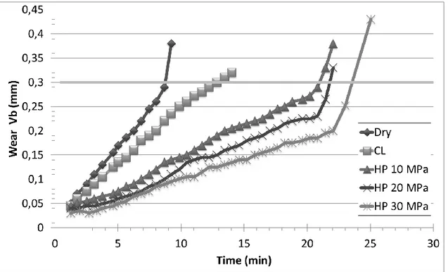
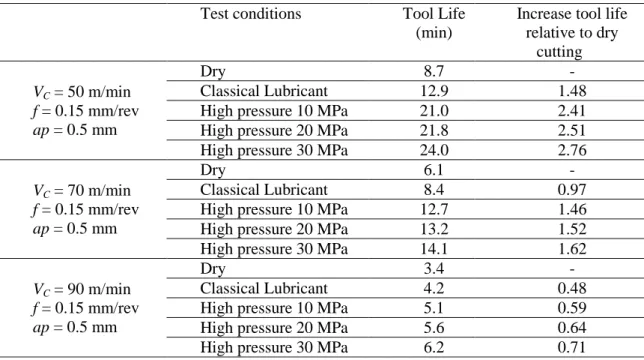
Wear tests were conducted at three different cutting speeds for classical lubrication and HP assistance at 10, 20 and 30 MPa. In this part, the feed and the cutting depth are held constant and equal to 0.15 mm/rev and 0.5 mm respectively. The cutting speeds chosen for investigation are 50, 70 and 90 m/min. The tool life criteria specified in ISO 3685 Standard (1993) is an average flank wear exceeding 300 µm or a maximum flank wear exceeding 600 µm. In all tests, the average flank wear reached the 300 µm limit before the 600 µm maximum flank wear limit. So only the average flank wear Vb is represented in Figure 9, which shows the evolution of this parameter for a cutting speed of 50 m/min. A summary of the times to failure for all test conditions are given in Table 3.
The results show that HP assistance protects the tool. Indeed, tool wear progresses more slowly with HP assistance, which greatly increases the tool life. These tests also demonstrate that this protective role is more effective when the pressure is high. However, Figure 9 shows that the start
of catastrophic wear appears at average flank wear values reduced for high pressure assisted machining compared to dry machining. For example, for a jet pressure of 10 MPa, catastrophic wear appears when Vb reaches 0.27 mm, while, for 30 MPa, it appears at a value of Vb = 0.2 mm. The emergence of catastrophic wear, depending on the assistance pressure, has also been highlighted by Ayed (2013). It is due to increased crater wear with increasing jet pressure. With increasing cutting speed, the gain produced by high pressure is less important (Table 3). For example, for a cutting speed of 50 m/min, the tool life is 8 min 45 sec for dry machining, and 21 min for a pressure of 10 MPa. This corresponds to a gain of 141% compared to dry machining. For the same pressure, this gain is reduced to 50% for a cutting speed of 90 m/min.
Figure 9: Evolution of average flank wear as a function of machining time for dry conditions, classical lubrication and different high pressure conditions (VC = 50 m/min, f = 0.15 mm/rev, ap = 0.5 mm).
Table 3: Summary of tool life for each test conditions. Test conditions Tool Life
(min)
Increase tool life relative to dry cutting VC = 50 m/min f = 0.15 mm/rev ap = 0.5 mm Dry 8.7 - Classical Lubricant 12.9 1.48
High pressure 10 MPa 21.0 2.41
High pressure 20 MPa 21.8 2.51
High pressure 30 MPa 24.0 2.76
VC = 70 m/min f = 0.15 mm/rev ap = 0.5 mm
Dry 6.1 -
Classical Lubricant 8.4 0.97
High pressure 10 MPa 12.7 1.46
High pressure 20 MPa 13.2 1.52
High pressure 30 MPa 14.1 1.62
VC = 90 m/min f = 0.15 mm/rev ap = 0.5 mm
Dry 3.4 -
Classical Lubricant 4.2 0.48
High pressure 10 MPa 5.1 0.59
High pressure 20 MPa 5.6 0.64
High pressure 30 MPa 6.2 0.71
The greater part of the tool life with HP assistance is most probably due to two related
phenomena: better fragmentation and chip removal, and improved thermal cutting conditions. For the first phenomenon, better fragmentation with HP assistance has been shown in Part 3. Moreover Part 4 has highlighted the friction reduction by decreasing the coefficient of friction for HP conditions. Indeed, the coolant jet forms a hydrodynamic interface between the chip and the tool also reducing the contact area, as shown on Figure 10. This figure namely shows the length of the friction zone measured for all tests on the insert using an optical microscope and a
Figure 10: Evolution of the measured contact length as functions of the jet pressure and cutting speed (f = 0.15 mm/rev, ap = 0.5 mm).
For the second phenomenon, it is likely that the cutting temperature decreases sharply with the use of HPC assistance. For low pressures, the water can vaporize in the cutting zone and interfere with heat transfer (Kaminski and Alvelid, 2000). For high pressures, the jet is localized and allows forced cooling at the tool-chip interface thereby improving heat transfer to the fluid (Vosough and Svenningsson, 2005). Rapid evacuation of the chips due to better fragmentation also contributes to reducing the interface temperature. In addition, lower friction for HPC assistance indicates less heat generation and hence lower temperature during machining.
6. INFLUENCE OF HIGH PRESSURE COOLANT ON SURFACE INTEGRITY The effect of the water jet on the workpiece surface integrity was also investigated via the study of the surface roughness and residual stresses. Roughness measurements were performed on machined surfaces to analyze the effect of different cutting parameters and the coolant pressure
on the surface of the workpiece. The roughness values reported in this study are an average of three measurements taken perpendicular to the machining grooves on two different places of the machined surface. The measurements were performed using a Hommel Tester T500® roughness meter. In this study, the arithmetic mean surface roughness, Ra (μm), and the total height of roughness profile, Rt (μm), were studied. Figure 11 shows the values of Ra and Rt for a feed of 0.15 mm/rev and a cutting depth of 0.5 mm at cutting speed ranging from 10 to 100 m/min and for various environmental conditions (Dry cutting, High Pressure 10, 20 and 30 MPa).
Figure 11: Ra and Rt roughness parameters for different environmental conditions as a function of cutting speed (f = 0.15 mm/rev, ap = 0.5 mm).
The roughness criteria Ra and Rt decreased significantly with increasing jet pressure. For a cutting speed of 50 m/min, Rt decreases from 3.8 µm for dry machining to 2.95 µm for water jet assisted machining (20 MPa). The arithmetic average roughness Ra decreases from 0.82 µm to 0.57 µm. Ezugwu et al. (2007) also observed an improvement of surface roughness with high pressure assistance with new tool inserts.
Residual stresses are determined via the X-ray diffraction technique, using a PROTO-XRD machine. The stresses are studied in two directions: in the direction of cutting (i.e. the circumferential stress) and the feed direction (i.e. the axial stress). The residual stresses, as a function of the depth, are determined after electro-chemically polishing the surface of the workpiece. The resulting stress profiles are shown in Figure 12 for Vc = 50 m/min, f = 0.15 mm/rev, ap = 0.5 mm. The first result is that the influence of the coolant pressure is significant at the surface of the sample. Axial and circumferential residual stresses are in
compression at the surface of the workpiece for all test conditions. The maximum axial stress in compression is located in the sub-surface (around 15 µm from the surface) of the sample. The compressive surface axial stress goes from -400 MPa for dry machining to approximately -700 MPa for HPC assistance with a pressure of 30 MPa. Another result is that HPC assistance has little influence on the residual stresses within the depth of the workpiece. Indeed, beyond 85 µm from the surface of the sample, every stress profile is quite the same. Figure 12 shows that the use of high-pressure coolant does not have a great influence on the depth of the residual stress field. These results are in agreement with those obtained by Habak and Lebrun (2011) for the turning of an austenitic stainless steel.
Figure 12: Axial and circumferential residual stresses profiles for the Ti555-3 alloy machined under different environmental conditions (Vc = 50 m/min, f = 0.15 mm/rev, ap = 0.5 mm).
When analyzing the results of stresses determined via X-ray diffraction, an important parameter is the mean peak width (MPW) which reflects the hardening level and the depth affected by hardening in the workpiece. Figure 13 shows the evolution of this parameter for the test conditions already defined for Figure 12.
For all cases, the peak width at the surface is high (> 4°), which represents significant hardening. High pressure coolant assisted tests conducted at a pressure of 30 MPa lead to MPW of 4° whereas a dry environment induces MPW values close to 4.3°. For high pressure water jet
assisted machining, the level of strain hardening decreases more rapidly to the stabilized value of 2° corresponding to that of original material (Figure 13). These results are consistent with the micro-hardness analysis conducted by Ezugwu et al. (2007) on a Ti6Al4V alloy machined under different high coolant pressures. These authors show a clear tendency of minimizing the
of the jet to the chip-tool interface, which contributes, in particular, to reducing friction coefficient. The lower friction coefficient associated to the lower cutting forces lead for the Ti555-3 alloy to less hardening under HPC conditions.
Residual stresses and MPW values result in a complex competition between thermo-mechanical effects (M'Saoubi et al., 1999). If the hardening under HPC conditions is lower than under dry environment, its localization at the surface of the sample is more pronounced leading to a more important gradient effect. This induces more compressive residual stresses under HPC conditions than under dry environment. In parallel, the thermal action of the coolant jet leading to surface cooling also promotes compressive residual stresses. Nonetheless, precisely uncoupling mechanical effects from thermal ones remains an opening question.
Figure 13: Mean Peak width evolution as function of pressure.
Figure 14 shows evolution of surface residual stresses as a function of pressure (Vc = 50 m/min,
ap = 0.5 mm, f = 0.15 mm/rev). Surface residual stresses show a rapid drop to more compression,
immediately. If the pressure is increased, surface residual stresses continue to decrease, but more slowly. Thus the cooling effect of the high-pressure coolant jet in the cutting zone is effective even for a pressure of a few MPa.
Figure 14: Evolution of surface residual stresses as a function of pressure (Vc = 50 m/min, ap = 0.5 mm, f = 0.15 mm/rev).
7. CONCLUSIONS
This work deals with the use of high pressure coolant assistance for the machining of the Ti555-3 titanium alloy. It has been demonstrated that this type of assistance is beneficial for the
machining of this material and is very interesting from an industrial point of view. This work leads to the following conclusions:
- Chip fragmentation is made possible with tool inserts that would not previously produce this type of behavior. For the tested cutting parameters, it can be obtained with a pressure of 5 MPa, but is optimum with a pressure of 20 MPa.
- Tool life is greatly increased (8.7 min under dry conditions to 24 min with HPC 30 MPa for a cutting speed of 50 m/min).
- Surface integrity is improved. The Ra surface roughness parameter decreases from 0.82 µm under dry conditions to 0.57 µm with HPC 30 MPa. Strain hardening is decreased and more localized at the surface of the workpiece. Surface residual stresses become more compressive.
These effects have been attributed to the thermo-mechanical action of the coolant jet resulting in lower cutting forces, lower coefficient of friction and lower temperature in the cutting zone. Further investigations have to be done to more precisely uncouple the mechanical action of the jet from the thermal one.
Thus, significant gains can be achieved with high pressure coolant. This assistance is proved to be a really attractive way to improve machinability of the Ti555-3 alloy.
REFERENCES
ISO 3685 (1993) Tool-life testing with single-point turning tools.
AFNOR Norm NF E66-520 (2008) Working zones of cutting tools - couple tool-material, part 1 to 8.
Abdel-Aal, H.A.; Nouari, M.; El Mansori, M. (2009) Influence of thermal conductivity on wear when machining titanium alloys. Tribology International, 42 (2): 359-372.
Arrazola, P.J.; Garay, A.; Iriarte, L.M; Armendia, M.; Marya, S.; Le Maître, F. (2009) Machinability of titanium alloys (Ti6Al4V and Ti555.3). Journal of Materials Processing Technology, 209 (5) (3/1): 2223-30.
Ayed, Y., Germain, G., Ammar, A., Furet, B. (2013) Degradation modes and tool wear
mechanisms in finish and rough machining of Ti17 Titanium alloy under high-pressure water jet assistance. Wear, 305 (1-2): 228-237
Barry, J.; Byrne, G. (2002) TEM study on the surface layer in two turned hardened steels. Materials Science and Engineering, A 325 (1-2): 356-364.
Bermingham, M. J.; Palanisamy, S.; Kent, D.; Dargusch, M.S. (2012) A comparison of cryogenic and high pressure emulsion cooling technologies on tool life and chip morphology in Ti-6Al-4V cutting. Journal of Materials Processing Technology, 212 (4): 752-65.
Courbon, C.; Kramar, D.; Krajnik, P.; Pusavec, F.; Rech, J.; Kopac J. (2009) Investigation of machining performance in high-pressure jet assisted turning of Inconel 718: An experimental study. International Journal of Machine Tools and Manufacture, 49 (14): 1114-25.
Dhananchezian, M.; Pradeep Kumar, M. (2011) Cryogenic turning of the Ti-6Al-4V alloy with modified cutting tool inserts. Cryogenics, 51 (1): 34-40.
Ezugwu, E.O.; Bonney, J.; Da Silva, R.B.; Çakir, O. (2007) Surface integrity of finished turned ti-6Al-4V alloy with PCD tools using conventional and high pressure coolant supplies.
International Journal of Machine Tools and Manufacture, 47 (6): 884-91.
Ezugwu, E.O.; Bonney, J.; Yamane, Y. (2003) An overview of the machinability of aeroengine alloys. Journal of Materials Processing Technology, 134 (2) (3/10): 233-53.
Ezugwu, E.O.; Wang, Z.M. (1997) Titanium alloys and their machinability—a review. Journal of Materials Processing Technology, 68 (3) (8/15): 262-74.
François, M.; Sprauel, J.M.; Déhan, C.F.; James, M.R.; Convert, F.; Lu, J.; Lebrun, J.L.; Ji, N.; Hendrics, R.W. (1996) X-ray diffraction method. Handbook of Measurement of Residual Stresses: 71-131.
Habak, M.; Lebrun, J.L. (2011) An experimental study of the effect of high-pressure water jet assisted turning (HPWJAT) on the surface integrity. International Journal of Machine Tools and Manufacture, 51 (9): 661-9.
Hauk, V. (1997) St ructural and Residua l Stress Anal ys is b y Nondest ructive Methods : Evaluation - Appli cation – Assessment . Els evi er S ci ence ed.
Kaminski, J.; Alvelid, B. (2000) Temperature reduction in the cutting zone in water-jet assisted turning. Journal of Materials Processing Technology, 106 (1-3): 68-73.
Khanna, N., Sangwan, K.S. (2013) Interrupted machining analysis for Ti6Al4V and Ti5553 titanium alloys using physical vapor deposition (PVD)-coated carbide inserts Proceedings of the Institution of Mechanical Engineers, Part B: Journal of Engineering Manufacture, 227 (3): 465-470.
Komanduri, R.; Von Turkovich, B. F. (1981) New observations on the mechanism of chip formation when machining titanium alloys. Wear, 69 (2): 179-88.
Krämer, A.; Lung, D. ; Klocke, F. (2012) High performance cutting of aerospace materials. 4th Manufacturing Engineering Society International Conference, MESIC 2011; Cadiz; Spain, 498: 127-132.
López De Lacalle, L. N.; Pérez-Bilbatua, J.; Sánchez, J. A.; Llorente, J. I.; Gutiérrez, A.;
Albóniga, J. (2000) Using high pressure coolant in the drilling and turning of low machinability alloys. International Journal of Advanced Manufacturing Technology, 16 (2): 85-91.
Machado, A. R.; Wallbank, J.; Pashby, I.R.; Ezugwu, E.O. (1998) Tool performance and chip control when machining Ti6A14V and Inconel 901 using high pressure coolant supply. Machining Science and Technology, 2 (1): 1-12.
Merchant, M.E. (1945) Mechanics of the metal cutting process. I. orthogonal cutting and a type 2 chip. Journal of Applied Physics, 16 (5): 267-75.
M'Saoubi, R.; Outeiro, J.C.; Changeux, B.; Lebrun, J.L.; Morão Dias, A. (1999) Residual stress analysis in orthogonal machining of standard and resulfurized AISI 316L steels. Journal of Materials Processing Technology, 96 (1-3): 225-33.
Nandy, A.K.; Gowrishankar, M.C.; Paul, S. (2009) Some studies on high-pressure cooling in turning of ti-6Al-4V. International Journal of Machine Tools and Manufacture, 49 (2): 182-98.
Nandy, A. K.; Paul, S. (2008) Effect of coolant pressure, nozzle diameter, impingemnt angle and spot distance in high pressure cooling with neat oil in turning ti-6AL-4V. Machining Science and Technology, 12 (4): 445-73.
Nouari, M., Makich, H. (2013) Experimental investigation on the effect of the material microstructure on tool wear when machining hard titanium alloys: Ti-6Al-4V and Ti-555 . International Journal of Refractory Metals and Hard Materials, 4: 259-269.
Palanisamy, S.; McDonald, S. D.; Dargusch, M.S. (2009) Effects of coolant pressure on chip formation while turning Ti6Al4V alloy. International Journal of Machine Tools and Manufacture, 49 (9): 739-43.
Ramesh, A.; Melkote, S.N.; Allard, L.F.; Riester, L.; Watkins, T.R. (2005) Analysis of white layers formed in hard turning of AISI 52100 steel. Materials Science and Engineering, A 390 (1-2): 88-97.
Sun, S.; Brandt, M.; Dargusch, M.S. (2009) Characteristics of cutting forces and chip formation in machining of titanium alloys. International Journal of Machine Tools and Manufacture, 49 (7– 8) (6): 561-8.
Venugopal, K. A.; Paul, S.; Chattopadhyay, A.B. (2007) Tool wear in cryogenic turning of ti-6Al-4V alloy. Cryogenics, 47 (1): 12-8.
Vosough, M.; Svenningsson, I. (2005) Influence of high pressure water jet-assisted machining on surface residual stresses on the work-piece of Ti-6Al-4V alloy. Proceedings of SPIE - The
International Society for Optical Engineering: 127-133.
Wagner, V.; Baili, M.; Dessein, G.; Lallement, D. (2011) Experimental study of coated carbide tools behaviour: Application for Ti-5-5-5-3 turning. International Journal of Machining and Machinability of Materials, 9 (3-4): 233-48.
Microstructure of the Ti555-3 titanium alloy investigated. 148x121mm (300 x 300 DPI)
High pressure coolant nozzle – geometrical characteristics. 182x63mm (300 x 300 DPI)
Sketch of the cutting area with high pressure coolant jet. 262x206mm (300 x 300 DPI)
Macro-photographs of the chips produced during turning of Ti555-3 alloy as a function of coolant pressure (Vc = 50 m/min, f = 0.15 mm/rev, ap = 0.5 mm).
Influence of jet pressure on the appearance of white bands in Ti555-3 chips with or without high pressure assistance (Vc = 50 m/min, f = 0.15 mm/rev, ap = 0.5 mm).
Specific cutting force as a function of the cutting speed and environment (Dry, Classical Lubricant, and HPC) for ap = 0.5 mm and f = 0.15 mm/rev.
Evolution of specific cutting force, for different environmental conditions, as a function of (a) the cutting depth for a feed f = 0.3 mm/rev and (b) the feed for a depth of cut, ap = 0.5 mm.
Evolution of the calculated apparent friction coefficient as functions of the jet pressure and cutting speed. 147x129mm (300 x 300 DPI)
Evolution of average flank wear as a function of machining time for dry conditions, classical lubrication and different high pressure conditions (VC = 50 m/min, f = 0.15 mm/rev, ap = 0.5 mm).
Evolution of the measured contact length as functions of the jet pressure and cutting speed (f = 0.15 mm/rev, ap = 0.5 mm).
Ra and Rt roughness parameters for different environmental conditions as a function of cutting speed (f = 0.15 mm/rev, ap = 0.5 mm).
Axial and circumferential residual stresses profiles for the Ti555-3 alloy machined under different environmental conditions (Vc = 50 m/min, f = 0.15 mm/rev, ap = 0.5 mm).
Mean Peak width evolution as function of pressure. 288x226mm (300 x 300 DPI)
Evolution of surface residual stresses as a function of pressure (Vc = 50 m/min, ap = 0.5 mm, f = 0.15 mm/rev).
Chemical composition of the Ti-5553 alloy. 66x9mm (300 x 300 DPI)
X-ray diffraction parameters for the Ti555-3 alloy. 65x8mm (300 x 300 DPI)
Summary of tool life for each test conditions. 247x137mm (300 x 300 DPI)
Comments to the Author
Review of LMST-2012-0174.R1
Reviewer: 11) What is new being presented in this article? Please put this information in the abstract. Reply:
The sentence has been added in the abstract:
“The originality of this paper is the quantification of productivity gains and the improvement in surface integrity seen for a recent titanium alloy that is seeing increasing use in the aeronautical industry.”
2) Please incorporate more recent references on machinability of titanium alloys. Reply:
The following two references have been added:
Nouari, M., Makich, H. (2013) Experimental investigation on the effect of the material microstructure on tool wear when machining hard titanium alloys: Ti-6Al-4V and Ti-555. International Journal of Refractory Metals and Hard Materials, 4: 259-269.
Khanna, N., Sangwan, K.S. (2013) Interrupted machining analysis for Ti6Al4V and Ti5553 titanium alloys using physical vapor deposition (PVD)-coated carbide inserts Proceedings of the Institution of Mechanical Engineers, Part B: Journal of Engineering Manufacture, 227 (3): 465-470.
This paper now incorporates 14 references less than 5 years.
3) A deeper discussion of the results obtained is necessary. In the discussion of the results development, it is very important to emphasize points of agreement or disagreement between results in this work and others cited in references part of manuscript.
Reply:
The authors do not agree with this comment. A great effort has been made to discuss the results in light of other published work. There are 33 cited papers in the article with approximately 20 in the discussion of the results.
4) Please include a table (s) with the values of the experimental results. Reply:
The authors do not understand this request. Certain results are already presented in table form (ex. Table 3 – Summary of tool life for each test conditions) and others as graphs. It is impossible to summarize all of the results in a single table and the authors feel that for certain cases a graph is more appropriate.
5) Improve the conclusions. Reply:
The following sentence has been added to the conclusion:
“This work deals with the use of high pressure coolant assistance for the machining of the Ti555-3 titanium alloy. It has been demonstrated that this type of assistance is beneficial for the machining of this material and is very interesting from an industrial point of view.
This work leads to the following conclusions:”
6) The document also required a spell/grammar check. Reply:
The manuscript has been completely revised in terms of grammar and spelling by native English speaker.
Reviewer: 2
Corresponding Author: guenael.germain@ensam.eu ; Phone : (+33) 241 207 343 ; Fax number : (+33) 241 207 320 ; Full postal address: Arts et Métiers ParisTech, LAMPA-EA1427, 2, Bd de Ronc
INFLUENCE OF HIGH PRESSURE COOLANT ASSISTANCE ON
THE MACHINABILITY OF THE TITANIUM ALLOY TI555 -3
(Influence of HPC on the machinability of Ti555-3)
T. Braham-Bouchnaka, G. Germaina, A. Morela, B. Furetb
a
Arts et Métiers ParisTech, LAMPA-EA1427, 2, bd de Ronceray 49000 Angers, France
b
IUT Nantes, IRCCyN, 2 avenue du Professeur Jean Rouxel 44475 Carquefou, France
ABSTRACT
The originality of this paper is the quantification of productivity gains and the improvement in surface integrity seen for a recent titanium alloy that is seeing increasing use in the aeronautical industry. The Ti555-3 titanium alloy, which is starting to find greater application in the
aeronautical field, exhibits certain difficulties in terms of machining. High Pressure Coolant (HPC) assisted turning consists of projecting a high pressure coolant jet between the chip and the tool. Comparisons are made between assisted turning using variable jet pressure and conventional turning (dry and classical lubrication). It is shown that it is possible to improve productivity by using HPC assisted machining. The results highlight good chip fragmentation and a great improvement of tool life with HPC assistance. Surface integrity is also shown to be improved, through surface roughness parameters which decrease, and surface residual stresses which
become more compressive. These effects have been attributed to the thermo-mechanical action of
the coolant jet resulting in lower cutting forces, lower coefficient of friction and lower temperature in the cutting zone.
KEYWORDS: High Pressure Coolant; Machinability; Titanium alloys; Surface integrity; Tool life; Cutting Force.
1. INTRODUCTION
To improve the performance of aircraft components, new materials with high strength to weight ratios are sought out and developed. These materials result in a reduction of mass and by
consequence greater fuel efficiency of the final product. Among these materials, titanium alloys are commonly used and in particular the new titanium alloy Ti555-3 is seeing much greater interest. This alloy possesses better mechanical properties compared to the Ti6Al4V alloy. But the difficulties associated with the machining of titanium alloys are well known in the industry (Krämer et al., 2012) and are related in the literature to their mechanical, chemical and thermal properties (Ezugwu and Wang, 1997). These materials have low thermal conductivity, which limits heat transfer and causes strong localization of the cutting temperature in the zone at the tool tip. Moreover they retain high hardness and resistance at high temperatures (up to 800°C). As a result the cutting tool is subjected to high stresses and high temperature. In these conditions, titanium alloys also exhibit a high chemical affinity with most components used in the surface treatment of cutting tools, leading to rapid tool wear (Komanduri and Von Turkovich, 1981). Arrazola et al. (2009) and Nouari et al. (2013) compared the machinability of the Ti555-3 and Ti6Al4V alloys and showed that the machinability of Ti555-3 is even lower than that of Ti6Al4V. Wagner et al. (2011) and Khanna et al. (2013) obtained the same results by studying more specifically the tool wear.
One avenue for improving the machinability of these materials is therefore to promote heat removal (Abdel-Aal et al., 2009). Two investigation paths can be followed. The first is cryogenic assisted machining which has been proved on a Ti6Al4V alloy, to decrease the tool wear
(Venugopal et al., 2007). Dhananchezian et al. ( 2011) measured with this assistance on the same alloy a decrease of the cutting force (35-42%) and of the flank wear (27-39%). A second possible way is the use of a high pressure coolant assistance. Recent studies showed that this assistance offers better tool life (Nandy and Paul, 2008) and chip breakage (Bermingham et al., 2012) than the cryogenic one on a Ti6Al4V alloy. However to the authors’ knowledge there are no
publications concerning the effects of high pressure coolant assistance in the machining of the Ti555-3 titanium alloy.
The current investigation precisely focuses on High Pressure Coolant (HPC) assisted turning of the Ti555-3 alloy. Since machining leaves a residual stress gradient on the surface of the
workpiece that influences the fatigue, fracture and corrosion behavior of the final machined part, it is necessary to know the residual stresses gradient after machining. So the effects of HPC in terms of chip morphology, cutting forces, tool wear and above all surface integrity of the workpiece will be analyzed and discussed.
2. EXPERIMENTAL
This investigation focus on the Ti555-3 titanium alloy with a hardness of 354 ± 12 Hv whose chemical composition is presented in Table 1. The Ti555-3 alloy consists of a β phase matrix with a body-centred cubic structure and α phase particles in the form of nodules, ranging in size from about 1 to 5 µm (Figure 1).
Al V Cr Mo Fe H C O N Ti 5553 4.91 5.25 2.98 5.22 0.35 0.001 0.008 0.135 0.006
Figure 1: Microstructure of the Ti555-3 titanium alloy investigated.
Turning experiments were carried out on a RAMO lathe. Machining was conducted under dry, classical lubrication and high-pressure coolant environment (5, 10, 20, 30 MPa). Under classical lubrication, overhead flood cooling was undertaken at a flow rate of 30 l/min using the standard coolant delivery system fitted with the lathe. Under classical lubrication and high-pressure coolant environment, the lubricant used was a chemical-based water soluble oil (5% Ecocool, Flush). A Hammelmann HDP 42 high pressure pump supplied room temperature coolant with a maximum flow rate of 42 liters per min and a maximum pressure of 48 MPa. The tool holder has been specifically designed by Sandvik Coromant. It is directly fixed to a “Kistler 9257B”
angled at 15° to the tool holder (Figure 2). The jet pressure and flow rate were measured using a manometer fixed on the tool holder and a digital flowmeter.
Figure 2: High pressure coolant nozzle – geometrical characteristics.
Previous work shows that this configuration enables to fit the coolant between the chip and the tool so that it modifies the contact in the secondary shear zone (Habak and Lebrun, 2011). Figure 3 sketches the high pressure coolant jet in the cutting area. Position of the different shear zones is also defined.
Figure 3: Sketch of the cutting area with high pressure coolant jet.
All tests were performed with carbide inserts of type S05F DNMG 15 06 08 from Sandvik ®. The tool cutting edge angle has a value of 95°. The tool inserts were changed in each test so that the results are not affected by wear. Various combinations of cutting parameters were
investigated (cutting speed Vc ranging from 20 to 90 m.min-1, feed f ranging from 0.1 to 0.3 mm/rev, and depth of cut ap ranging from 0.2 to 1 mm).
SE C
SE C
The lathe was fitted with a Kistler® dynamometer for measuring the three components of the cutting force. These measurements were conducted for each test as well as the surface roughness. The machined chips were also collected and analyzed after each cut. For certain tests, tool wear was investigated as mentioned in ISO 3685 Standard (1993) for tool life testing, and the residual stresses were analyzed, by the x-ray diffraction technique. To analyze the residual stress fields in the workpiece after machining, a PROTO portable X-ray diffractometer was used to determine the diffraction peaks and automatically process the results. The system is based on the sin²ψ method. The principle is to use the variation of the atomic spacing as strain gauge (François et al., 1996). The parameters associated with the residual stress analyses done in this work are presented in Table 2.
Table 2: X-ray diffraction parameters for the Ti555-3 alloy.
Bragg angle Diffraction plane Radiation Collimator diameter
139.6° [213] CuKα 2 mm
The stresses are determined in the axial and circumferential directions of the workpiece. The uncertainty of each measurement point is estimated to be +/- 50 MPa. The analysis of the residual stress evolution as a function of depth was conducted by electrochemically removing a layer of material between each measurement. The stress profiles are analyzed in conjunction with the diffraction peak widths. These values give an indication of the level of strain hardening of the workpiece.
3. INFLUENCE OF HIGH PRESSURE COOLANT ON CHIP MORPHOLOGY In order to investigate the influence of pressure coolant on chip morphology, the machining were carried out under dry, classical lubrication and high-pressure water soluble oil environment (5, 10, 20, 30 MPa). All other process parameters were kept constant (Vc = 50 m/min, f = 0.15 mm/rev, ap = 0.5 mm, and length of cut L = 20 mm). As length of cut is quite small and tool inserts are changed in each test, the wear of the tool is not significant on chip morphology. Figure 4 shows the influence of the jet pressure on chip fragmentation. The chips have been classified according to ISO 3685 Standard (1993). When machining under dry conditions or with classical lubrication, long cylindrical helical chips are produced. Chips are fragmented at a pressure of 5 MPa but the length of the chip is too large (approx. 100 mm) for efficient removal. The chips are well fragmented for jet pressures greater than 10 MPa. Their length decreases with increasing pressure.
Moreover, at a pressure of 30 MPa, the chips become so thin (approx. 3 mm), that it could be harmful to the lathe by becoming wedged into its various elements (slider, spindle, etc). For a pressure of 20 MPa, good chip fragmentation is achieved. With high pressure, the chip wraps up (forming small arcs) and quickly breaks (López De Lacalle et al., 2000). This process occurs faster when the pressure is higher. This observation has also been made by several authors on a nickel alloy (Courbon et al., 2009) and on a Ti6Al4V titanium alloy (Nandy and Paul, 2008; Palanisamy et al., 2009). The jet physically breaks the chip segment (Bermingham et al., 2012).
Figure 4: Macro-photographs of the chips produced during turning of Ti555-3 alloy as a function of coolant pressure (Vc = 50 m/min, f = 0.15 mm/rev, ap = 0.5 mm).
Micrographs of the chips obtained under dry conditions and with high coolant pressure jet (20 MPa) are presented on Figure 5. This alloy has the peculiarity of forming white bands in both the primary and secondary shear zones. These layers are so called “white” because they are very hard and resistant to standard etchants used in metallographic studies. These white-etching layers are not observed in the Ti6Al4V alloy (Sun et al., 2009). But they are noticed in the literature in the hard turning of steel (Ramesh et al., 2005). The common agreement, based on TEM observations (Barry and Byrne., 2002), lies in the fact that they are composed of very fine grains. The
occurrence of phase transformation is discussed. The bands appear due to a strong rise in temperature and / or intense localized plastic deformation. The thickness of the white bands is approximately 4 µm in the primary shear zone for the two configurations (dry machining and HPC with 20 MPa). However, in the secondary shear zone the thickness of the white bands is approximately 15 µm in dry machining and around 5 µm of the HPC configuration. Palanisamy et al. (2009) show on a Ti6Al4V alloy that the shear band thickness increases in the secondary SE
shear zone with increasing coolant pressure for the same cutting conditions. Their results are consistent with this study. Indeed, if the tendency for shear localization is lower with high pressure coolant, the white-etching layers are less likely to form. The high pressure coolant acts directly between the chip and the tool (i.e. on the secondary shear zone) and effectively cools this zone. In contrast, the white bands created in the primary shear zone are similar, with and without assistance, as observed by Machado et al. (1998). These findings indicate that the action of the coolant jet mainly influence the secondary shear zone and has a very limited effect on the primary shear zone.
Figure 5: Influence of jet pressure on the appearance of white bands in Ti555-3 chips with or without high pressure assistance (Vc = 50 m/min, f = 0.15 mm/rev, ap = 0.5 mm).
4. INFLUENCE OF HIGH PRESSURE COOLANT ON THE CUTTING FORCES The tests are based on Tool-Material Pair (AFNOR Norm NF E66-520, 2008) to determine the evolution of the specific cutting force (i.e. the ratio of the cutting force to the area of the
undeformed chip) in conventional lubrication and high pressure coolant assisted tests. The cutting speed has been increased from 20 to 90 m/min in increments of 10 m/min. The feed f is fixed at 0.15 mm/rev and the depth of cut ap at 0.5 mm. For each test, the three components of the cutting force were measured during machining by means of a Kistler® dynamometer. As the three
components of the cutting force have similar evolutions, only the tangential cutting force will be discussed below. The results are shown in Figure 6.
The general shape of the curves correspond to the classic behavior for which the specific cutting force decreases with increasing cutting speed, then stabilizes at the cutting speed referred to as
Vcmin.
Figure 6: Specific cutting force as a function of the cutting speed and environment (Dry, Classical Lubricant, and HPC) for ap = 0.5 mm and f = 0.15 mm/rev.
These curves allow the minimum speed cutting, Vcmin, to be determined for the different cutting configurations. Vcmin tends to increase slightly with increasing jet pressure: Vcmin is 50 m/min for the Conventional Lubricant test and 65 m/min for the High Pressure assisted test (30 MPa). Figure 6 also shows that the specific cutting force decreases with increasing coolant pressure. Indeed, for a feed of 0.15 mm/rev and a cutting depth of 0.5 mm, the decrease is about 23% between conventional lubricant and with a pressure of 30 MPa. This reduction is effectively
independent of the cutting speed. High pressure water jet assistance can thus decrease the cutting force, as observed by Nandy et al. (2009) on a Ti6Al4V alloy
Additional tests at constant cutting speed (Vc = 50 m/min) were conducted to show the influence of high pressure as a function of feed and cutting depth (Figure 7). These tests were done in different configurations with a cutting depth ranging from 0.2 mm to 1 mm, a feed ranging from 0.1 mm/rev to 0.3 mm/rev and 5 environmental configurations (Dry, Conventional Lubricant, High Pressure: 10 MPa, 20 MPa and 30 MPa).
These tests showed that the specific cutting force tends to decrease with the increase in feed and cutting depth (Figure 7). In addition, for all configurations, increasing the jet pressure decreases the specific cutting force (and hence the cutting force). Figure 7 also shows that the decrease in specific cutting force is greater for small cutting depths and for high feeds.
Figure 7: Evolution of specific cutting force, for different environmental conditions, as a function of (a) the cutting depth for a feed f = 0.3 mm/rev and (b) the feed for a depth of cut, ap = 0.5 mm.
Indeed, for high feeds, the decrease in the specific cutting force, KCT, is up to 20% (f =
0.3 mm/rev) depending on the different lubrication configurations. For low feeds, there is only a small effect, 5% (f = 0.1 mm/rev). This can easily be explained, because when the feed is
increased the chip width increases, presenting a larger surface to the action of the jet, while its thickness (which is related to the cutting depth) remains low. Hence, HPC assistance is more efficient for high feeds.
Similarly, the influence of the coolant jet pressure as a function of the cutting depth changes significantly. When the cutting depth is large (1 mm), the jet is less efficient than for low cutting depths. For a cutting depth of 0.2 mm, the high pressure jet decreases the specific cutting force by 29% while for 1 mm cutting depth, this decrease is only 6%. This can also be easily explained by the fact that increasing the cutting depth increases the chip thickness. Hence, they are more resistant to fragmentation. Furthermore, an increase of cutting depth does not significantly change the surface area exposed to the action of the coolant jet.
From these tests, it can be concluded that the type of lubrication (Dry, Classical Lubrication, or High Pressure) significantly influences the cutting forces. The decrease in cutting force with HP assistance is greater when the pressure is high. Furthermore, the effectiveness of HPC assistance is greater when the cutting depth is small and when the feed HPC is high. These trends have similarly been noted by Ezugwu et al. (1997) on titanium alloys, and for the machining of Inconel 718 with high pressure water jet assistance (20 MPa with a feed rate of 0.2 mm/rev) (Ezugwu et al., 2003).
From measurements of cutting force components, the calculation of the apparent coefficient of friction μ can be done using the equation from the theory of Merchant (1945): (eq.1) where Fn and Ft are the normal and tangential cutting forces in the measurement coordinate system and γ is the rake angle. Figure 8 shows this apparent coefficient of friction as a function of the cutting speed and the coolant pressure. The apparent coefficient of friction decreases with increasing coolant pressure. The coolant jet directed between the tool and the chip facilitates the movement of the chip relative to the tool. The decrease is lower for higher cutting speeds. Indeed the increase in cutting speed leads to an increase of chip speed relative to the tool. Therefore, it is more difficult for the coolant jet to fit between the chip and the tool because it is strongly repelled by the movement of the chip. The high-pressure coolant assistance is then less effective. In a similar way, Nandy et al. (2009) evaluated apparent coefficients of friction from experimental data conducted on a Ti6Al4V alloy machined under high-pressure water soluble oil. Their results are consistent with this study. Increase in cutting speed leads to a decrease in apparent coefficient of friction. These authors explain these results by an increase in cutting temperature when
increasing cutting speed, leading to more micro-welding in the sliding zone, promoting higher friction. To their point, increase in coolant pressure provides lower friction by better cooling ability.
In parallel, the reduction of friction decreases the temperatures generated at the chip/tool
interface. Courbon et al. (2009) observed a 30% reduction in the temperature of the tool between a test at high pressure (90 MPa) and a conventional lubrication test. This drop in temperature can explain the reduction of white-etching layers thickness discussed in Part 3. It also must influence tool wear.
Figure 8: Evolution of the calculated apparent friction coefficient as functions of the jet pressure and cutting speed.
5. INFLUENCE OF HIGH PRESSURE COOLANT ON WEAR TESTS
Wear tests were conducted at three different cutting speeds for classical lubrication and HP assistance at 10, 20 and 30 MPa. In this part, the feed and the cutting depth are held constant and equal to 0.15 mm/rev and 0.5 mm respectively. The cutting speeds chosen for investigation are 50, 70 and 90 m/min. The tool life criteria specified in ISO 3685 Standard (1993) is an average flank wear exceeding 300 µm or a maximum flank wear exceeding 600 µm. In all tests, the average flank wear reached the 300 µm limit before the 600 µm maximum flank wear limit. So only the average flank wear Vb is represented in Figure 9, which shows the evolution of this parameter for a cutting speed of 50 m/min. A summary of the times to failure for all test conditions are given in Table 3.
The results show that HP assistance protects the tool. Indeed, tool wear progresses more slowly with HP assistance, which greatly increases the tool life. These tests also demonstrate that this protective role is more effective when the pressure is high. However, Figure 9 shows that the start
of catastrophic wear appears at average flank wear values reduced for high pressure assisted machining compared to dry machining. For example, for a jet pressure of 10 MPa, catastrophic wear appears when Vb reaches 0.27 mm, while, for 30 MPa, it appears at a value of Vb = 0.2 mm. The emergence of catastrophic wear, depending on the assistance pressure, has also been highlighted by Ayed (2013). It is due to increased crater wear with increasing jet pressure. With increasing cutting speed, the gain produced by high pressure is less important (Table 3). For example, for a cutting speed of 50 m/min, the tool life is 8 min 45 sec for dry machining, and 21 min for a pressure of 10 MPa. This corresponds to a gain of 141% compared to dry machining. For the same pressure, this gain is reduced to 50% for a cutting speed of 90 m/min.
Figure 9: Evolution of average flank wear as a function of machining time for dry conditions, classical lubrication and different high pressure conditions (VC = 50 m/min, f = 0.15 mm/rev, ap = 0.5 mm).
Table 3: Summary of tool life for each test conditions. Test conditions Tool Life
(min)
Increase tool life relative to dry cutting VC = 50 m/min f = 0.15 mm/rev ap = 0.5 mm Dry 8.7 - Classical Lubricant 12.9 1.48
High pressure 10 MPa 21.0 2.41
High pressure 20 MPa 21.8 2.51
High pressure 30 MPa 24.0 2.76
VC = 70 m/min f = 0.15 mm/rev ap = 0.5 mm
Dry 6.1 -
Classical Lubricant 8.4 0.97
High pressure 10 MPa 12.7 1.46
High pressure 20 MPa 13.2 1.52
High pressure 30 MPa 14.1 1.62
VC = 90 m/min f = 0.15 mm/rev ap = 0.5 mm
Dry 3.4 -
Classical Lubricant 4.2 0.48
High pressure 10 MPa 5.1 0.59
High pressure 20 MPa 5.6 0.64
High pressure 30 MPa 6.2 0.71
The greater part of the tool life with HP assistance is most probably due to two related
phenomena: better fragmentation and chip removal, and improved thermal cutting conditions. For the first phenomenon, better fragmentation with HP assistance has been shown in Part 3. Moreover Part 4 has highlighted the friction reduction by decreasing the coefficient of friction for HP conditions. Indeed, the coolant jet forms a hydrodynamic interface between the chip and the tool also reducing the contact area, as shown on Figure 10. This figure namely shows the length of the friction zone measured for all tests on the insert using an optical microscope and a
Figure 10: Evolution of the measured contact length as functions of the jet pressure and cutting speed (f = 0.15 mm/rev, ap = 0.5 mm).
For the second phenomenon, it is likely that the cutting temperature decreases sharply with the use of HPC assistance. For low pressures, the water can vaporize in the cutting zone and interfere with heat transfer (Kaminski and Alvelid, 2000). For high pressures, the jet is localized and allows forced cooling at the tool-chip interface thereby improving heat transfer to the fluid (Vosough and Svenningsson, 2005). Rapid evacuation of the chips due to better fragmentation also contributes to reducing the interface temperature. In addition, lower friction for HPC assistance indicates less heat generation and hence lower temperature during machining.
6. INFLUENCE OF HIGH PRESSURE COOLANT ON SURFACE INTEGRITY The effect of the water jet on the workpiece surface integrity was also investigated via the study of the surface roughness and residual stresses. Roughness measurements were performed on machined surfaces to analyze the effect of different cutting parameters and the coolant pressure
on the surface of the workpiece. The roughness values reported in this study are an average of three measurements taken perpendicular to the machining grooves on two different places of the machined surface. The measurements were performed using a Hommel Tester T500® roughness meter. In this study, the arithmetic mean surface roughness, Ra (μm), and the total height of roughness profile, Rt (μm), were studied. Figure 11 shows the values of Ra and Rt for a feed of 0.15 mm/rev and a cutting depth of 0.5 mm at cutting speed ranging from 10 to 100 m/min and for various environmental conditions (Dry cutting, High Pressure 10, 20 and 30 MPa).
Figure 11: Ra and Rt roughness parameters for different environmental conditions as a function of cutting speed (f = 0.15 mm/rev, ap = 0.5 mm).
The roughness criteria Ra and Rt decreased significantly with increasing jet pressure. For a cutting speed of 50 m/min, Rt decreases from 3.8 µm for dry machining to 2.95 µm for water jet assisted machining (20 MPa). The arithmetic average roughness Ra decreases from 0.82 µm to 0.57 µm. Ezugwu et al. (2007) also observed an improvement of surface roughness with high pressure assistance with new tool inserts.
Residual stresses are determined via the X-ray diffraction technique, using a PROTO-XRD machine. The stresses are studied in two directions: in the direction of cutting (i.e. the circumferential stress) and the feed direction (i.e. the axial stress). The residual stresses, as a function of the depth, are determined after electro-chemically polishing the surface of the workpiece. The resulting stress profiles are shown in Figure 12 for Vc = 50 m/min, f = 0.15 mm/rev, ap = 0.5 mm. The first result is that the influence of the coolant pressure is significant at the surface of the sample. Axial and circumferential residual stresses are in
compression at the surface of the workpiece for all test conditions. The maximum axial stress in compression is located in the sub-surface (around 15 µm from the surface) of the sample. The compressive surface axial stress goes from -400 MPa for dry machining to approximately -700 MPa for HPC assistance with a pressure of 30 MPa. Another result is that HPC assistance has little influence on the residual stresses within the depth of the workpiece. Indeed, beyond 85 µm from the surface of the sample, every stress profile is quite the same. Figure 12 shows that the use of high-pressure coolant does not have a great influence on the depth of the residual stress field. These results are in agreement with those obtained by Habak and Lebrun (2011) for the turning of an austenitic stainless steel.