Science Arts & Métiers (SAM)
is an open access repository that collects the work of Arts et Métiers Institute of Technology researchers and makes it freely available over the web where possible.
This is an author-deposited version published in: https://sam.ensam.eu
Handle ID: .http://hdl.handle.net/10985/7723
To cite this version :
Annie-Claude BAYEUL-LAINE, Patrick DUPONT, Giovanna CAVAZZINI, Patrick CHERDIEU, Antoine DAZIN, Gérard BOIS, Olivier ROUSSETTE - Comparisons Between Numerical
Calculations and Measurements in the Vaned Diffusor of SHF Impeller - journal of drainage and irrigation machinery engineering - Vol. 31, n°12, p.1013-1020 - 2013
Any correspondence concerning this service should be sent to the repository Administrator : [email protected]
Comparisons Between Numerical Calculations and
Measurements in the Vaned Diffusor of SHF Impeller
Annie-Claude Bayeul-Lainé1, Patrick Dupont2, Giovanna Cavazzini3, Patrick Cherdieu2, Antoine Dazin1, Gérard Bois1 and Olivier Roussette11. Arts et Métiers PARISTECH , LML (Laboratoire de Mécanique de Lille), UMR CNRS 8107, boulevard Paul Langevin, 59655 VILLENEUVE D’ASCQ Cedex, France
2. Ecole Centrale de Lille, LML (laboratoire de Mécanique de Lille), UMR CNRS 8107
3 University of Padova, Energy and Fluids, Department if Industrial Engineering
Abstract: The paper presents analysis of the performance and the internal flow behaviour in the vaned diffusor of a radial flow pump using PIV (Particle Image Velocimetry) and pressure probe traverses. PIV measurements have already been performed at mid height inside one diffusor channel passage for a given speed of rotation and various mass flow rates. These results have been already presented in several previous communications. New experiments have been performed using a 3 holes pressure probe traverses from hub to shroud diffusor width at different radial locations between the two diffusor geometrical throats. Numerical simulations are also realized with the commercial codes Star CCM+ 7.02.011 and CFX. Frozen rotor and fully unsteady calculations of the whole pump have been performed. Comparisons between numerical results, previous experimental PIV results and new probe traverses one’s are presented and discussed for one mass flow rate. In this respect, a first attempt to take into account fluid leakages between the rotating and fixed part of the pump has been checked since it may affect the real flow structure inside the diffuser.
Keywords: Vaned diffuser, Radial flow pump, unsteady flow, numerical calculations, Particle Image Velocimetry, three-holes probe.
1. Introduction
Knowledge improvement of rotor stator interactions in radial flow pumps has already been a favorite research theme for a large number of laboratories (references [1] to [5]). A great number of rotor stator interactions analyses based on modeling activities have been realized, but experimental analyses remain scarce. Thanks to nowadays computer performances and the evolution of PIV techniques (ref. [6] and [7]), it has been possible to measure velocity fields within the impeller and the diffuser of a radial flow pump. Tests have been performed in air with the so-called ‘SHF’ impeller for three kinds of diffusers: one vaneless and two differently vaned. Results
Corresponding author: Annie-Claude Bayeul-Lainé, Assistant Professor, research fields: turbomachinery, numerical simulation
E-mail: [email protected]
obtained with the vaneless diffuser have already been presented in previous symposia and published (see ref. [8] to [17]).
In numerical simulation, two aspects have to be considered. The first one concerns the governing equations which are solved in the model: two kinds of numerical calculations are currently used in turbomachinery (i-frozen rotor calculations, ii-unsteady calculations). The second aspect concerns the geometrical model. Some geometrical simplifications are currently used. For example, the leakage flows are often neglected. It is obvious that a complex model (fully unsteady, with leakage flows) will be more time consuming but closer to the real physics. The aim of the paper is to test several more or less sophisticated models to evaluate their ability to predict properly the pump performance and the internal flow behaviour. To do so, numerical results are compared to experimental
Comparisons Between Numerical Calculations and Measurements in the Vaned Diffusor of SHF Impeller 2
data (ref. [18]).
The existing database has been completed by pressure probe measurements for a complete flow performance analysis. These measurements are compared to several numerical calculations in the present paper. The experimental set-up and the numerical models are presented in the first parts of the paper. The comparisons and analysis of their results (global performance as well as velocity profile) within the diffuser are then discussed.
2. Experiments
2.1 Test and apparatus
Test pump model and PIV measurements conditions have been already described [8-10] and main geometrical characteristics as well as operating conditions are given in table 1. This set-up allows the existence of a “positive” leakage flow going into the gap between impeller outlet section and vaned diffusor inlet section which is specific to the experimental set-up. This is due to the fact that the pump outlet pressure corresponds to atmospheric conditions.
Table 1 Pump parameters Entry duct Diameter 0.14113 m length 0.25 m Impeller Inlet radius 0.14113 m Outlet radius 0.2549 m Number of blades Zi=7 Outlet height
Impeller design flow rate Rotation speed 0.04 m Qni=0.337m3/s N=1710 rpm Diffusor Inlet radius 0.2549 m Outlet radius 0.44 m Number of vanes Zd=8 Height
Diffusor design flow rate
0.04 m Qnd=0.8Qni Rotation speed 1710 rpm
2.2. Three –holes probe
A three holes probe (see Fig. 1) has been used to make hub to shroud traverses in the same planes
where wall static pressures are measured. Using a specific calibration one can get total pressure, static pressure, absolute velocity and its two components in radial and tangential direction.
Fig. 1 Picture and sketch of the three-holes pressure probe
2.3. General flow conditions
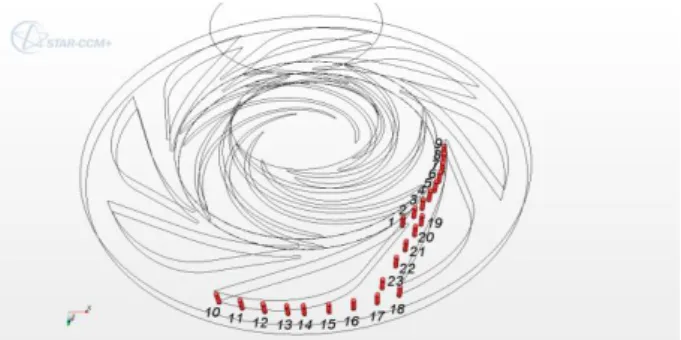
All types of measurements have been performed for several mass flow rates. But, results presented in this paper refer mainly to one mass flow rate corresponding to the design point of the vaned diffusor Q/Qni=0.766, which is different from impeller design mass flow rate Q/Qni=1. This vaned diffusor design was chosen in order to allow an enlarge pump performance characteristic curve for low mass flow rates. In order to well represent the flow field, twenty-three location positions are defined as it can be seen in Fig. 2. For each location, ten axial positions are registered (b*=0.125, 0.2, 0.25, 0.375, 0.5, 0.625, 0.75, 0.875, 0.925, 0.975). The present analysis focuses only on locations 19 to 23 in the blade to blade channel of the diffuser.
Fig. 2 Diffusor measurement locations for probe traverse and unsteady calculations
3. Calculations
Calculations were performed using Star CCM+ code and the results are compared to already published ones obtained with CFX [8-10].
3.1. Frozen rotor calculations (Star CCM+)
Three-dimensional steady incompressible Reynolds averaged Navier–Stokes equations are solved. The SST k- turbulence model is used [19].
The calculation domain was divided into three zones: the inlet zone, the impeller zone and the diffusor zone.
The boundary condition at the inlet consisted of a mass flow rate (0.305 kg/s; Q/Qni=0.766). The boundary condition at the outlet was the atmospheric pressure (0 Pa). The fluid (air) was considered incompressible at a constant temperature of 20ºC.
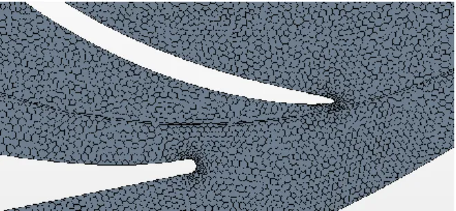
A polyhedral mesh with prism layers is used for all calculations (5 prism layers for a total prism layer thickness of 1 mm). The target size is 3 mm and the minimum size 0,5 mm . The size of the grid is about 3. 106 cells. A sketch of local mesh is given in Fig. 3.
Fig. 3 Local mesh between Impeller and diffusor
Fig. 4 Diffusor measurement locations for probe traverse and frozen rotor calculations
Line probes are plotted in the whole domain: Each probe is duplicated seven times in order to obtain all parameters (pressure, total pressure, radial, tangential and axial velocity and velocity magnitude) for seven different relative positions of the diffusor comparatively to the impeller (see Fig. 4). These ones are equal to 2.π.n/(1/Zi-1/Zd) with n=0,1 ,2, 3, 4, 5 and 6.
3.2. Unsteady calculations
3.2.1. Star CCM+
Fig. 5 y+ for unsteady calculations
The unsteady calculations were realized with the same mesh. The convergence criteria are less than 1.e-4. Maximum values of y+ are around 15, and mainly below 9 in the whole computational domain as can be seen in Fig.5.
A time step of 4.87e-5 s, corresponding to an angular rotation of 0.5°, has been chosen.
3.2.2. CFX
In order to investigate the influence of leakage flows, numerical results obtained using CFX are also presented. G. Cavazzini et al [8-10] proposed two kinds of unsteady simulations, with and without leakage flows.
As regards the simulations considering the leakage flows, the seal systems both at the impeller inlet and outlet were modelled (Figures 6, 7). At the labyrinth of the seal system close to the impeller inlet the mass flow rates determined from the experimental data was prescribed, assuming stochastic fluctuations of the velocities with 5 %
Comparisons Between Numerical Calculations and Measurements in the Vaned Diffusor of SHF Impeller 4
free-stream turbulence intensity. At the impeller outlet the leakage mass flow rate was controlled by the known experimental pressure in the large plenums upstream the labyrinth.
Much more details on model, mesh and numerical simulations are reported in ref [10].
Fig. 6 – Seal system at the impeller inlet
Fig. 7 – Seal system at the impeller outlet
4. Results and comparison
4.1. Global performances
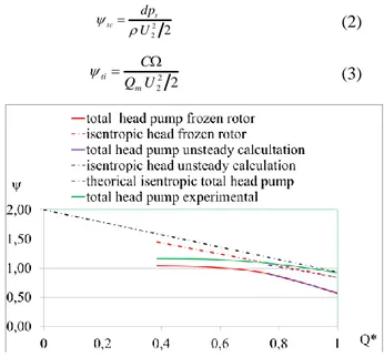
Fig 8 presents global results of the performance of the pump. In this figure Q* is defined as follows:
n
Q Q
Q* (1)
Non-dimensional calculated total head is defined by
equation (2) and non-dimensional isentropic head by equation (3) 2 2 2 U dpt tc (2) 2 2 2 U Q C m ti (3)
Fig. 8 Impeller non-dimensional head curve
Global results of total theoretical head pump are in good agreement between one dimensional approach and frozen rotor calculation. Unsteady calculation results, performed for the non-dimensional mass flow rate Q*=0,766, give the same level, as it can be seen in Fig. 8.
Comparison between real total head curve obtained by calculations and experiments are also given in the same figure. One has to note that pump mass flow rates are higher than impeller mass flow rates due to “positive” leakage flow. This is the reason why the experimental head pump is higher than the numerical total pump head coefficient.
4.2. Hub-to-shroud local flow characteristics.
The results obtained at location 19 has been chosen to compare frozen rotor and unsteady calculations,. Numerical results are shown in Fig. 9 and Fig. 10 respectively for frozen rotor and unsteady calculations. Radial velocity distributions depend on the relative impeller blade position compared with vaned diffusor ones as shown in Fig. 9, whereas only time acts for unsteady results. Unsteady calculations give smoother hub to shroud gradients and less difference between
blade to blade results.
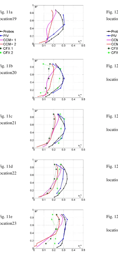
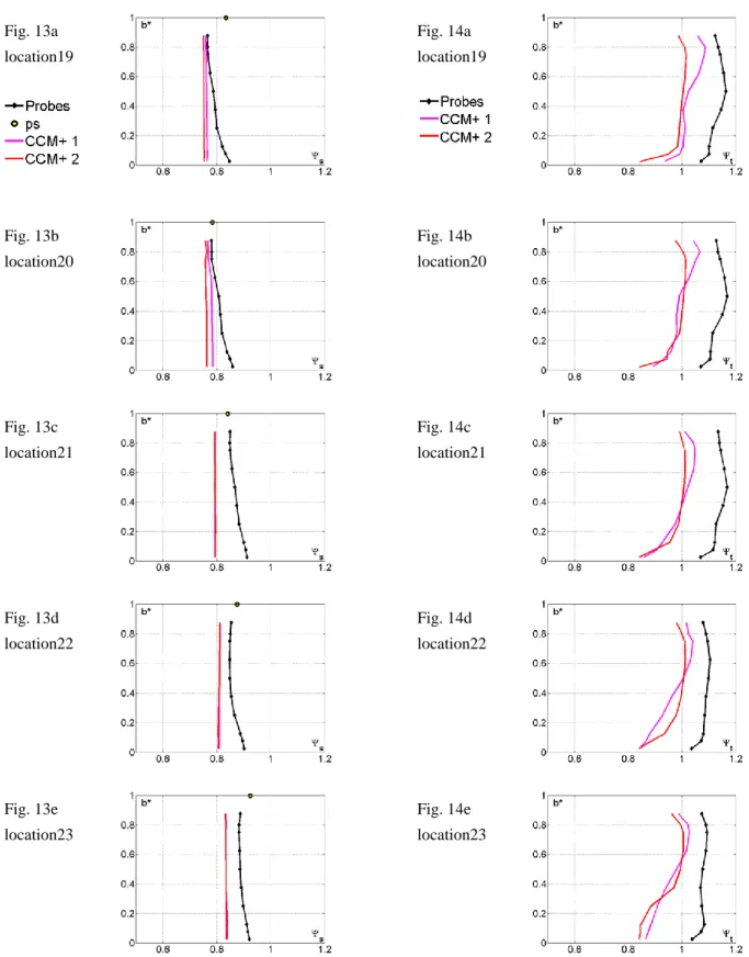
Local numerical results of frozen rotor calculations without leakage (“CCM+ 1”), unsteady calculations without leakage (obtained from two different codes: “CCM+ 2” and “CFX 1”), and unsteady calculations with leakage (obtained only from CFX [10]: “CFX 2”) are presented in Fig.11 to 14. PIV measurements (“PIV”), wall static pressure (”ps”) and three-holes pressure probes (“probes”) results are plotted on the same figures.
Fig. 9 hub-to-shroud non-dimensional radial velocity in different blade to blade channels for probe 19 (frozen rotor calculation)
Fig. 10 hub-to-shroud non-dimensional radial velocity in different blade to blade channels for probe 19 (unsteady calculation)
These experimental results have been performed with pump configuration with leakage. Results present radial and tangential velocities, static and total pressures distribution from hub to shroud section and for several channel locations as already shown in Fig.2.
The influence of leakage can be easily seen when comparing numerical results obtained without and with leakage. Experimental results are in good agreement with calculations obtained with leakage. This can be mainly seen on radial velocity distribution shown in Fig. 11. These results must be more deeply analysed, in particular PIV ones; they strongly depend on impeller position and only time-averaged values are presented here. Pressure probe results are also depending on unsteady effects and this has to be taken into account for further data reduction analysis.
The influence of leakage can also be seen, looking at pressure distributions in the diffusor. Static pressure recovery is better with leakage (Fig.14). Total pressure probe results show higher levels compared with calculations without leakage and also show that leakage effects acts mainly near shroud section preventing separation in location 22 and 23.
5. Conclusions
Comparisons between numerical frozen rotor assumption and fully unsteady calculations show that global performances can be obtained with frozen rotor assumption but that local values must be analysed with unsteady results even in the vaned diffusor far from impeller outlet section.
Results issued from different numerical approaches and experiments coming from PIV and pressure probe have been presented and compared. The pump model configuration allows leakage to be an important parameter that has to be taken into account in order to make good comparisons between numerical and experiments.
Acknowledgements
The authors wish to thank Region Nord- Pas de Calais and CNRS for their financial support in the frame of the CISIT program.
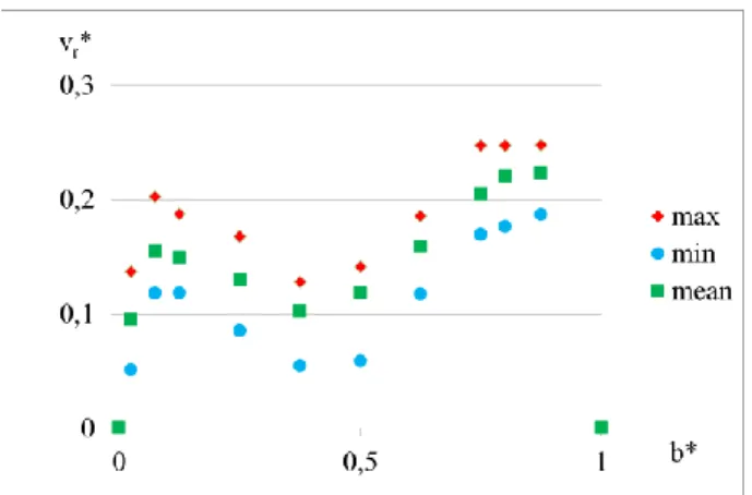
Comparisons Between Numerical Calculations and Measurements in the Vaned Diffusor of SHF Impeller 6 Fig. 11a location19 Fig. 11b location20 Fig. 11c location21 Fig. 11d location22 Fig. 11e location23
Fig. 11a to 11e hub-to-shroud non-dimensional radial velocity vr* for different locations inside the diffusor
channel Fig. 12a location19 Fig. 12b location20 Fig. 12c location21 Fig. 12d location22 Fig. 12e location23
Fig. 12a to 12e hub-to-shroud non-dimensional radial velocity vu* for different locations inside the diffusor
Fig. 13a location19 Fig. 13b location20 Fig. 13c location21 Fig. 13d location22 Fig. 13e location23
Fig. 13a to 13e hub-to-shroud non-dimensional pressure s for different locations inside the diffusor channel
Fig. 14a location19 Fig. 14b location20 Fig. 14c location21 Fig. 14d location22 Fig. 14e location23
Fig. 14a to 14e hub-to-shroud non-dimensional total pressure t for different locations inside the diffusor
Nomenclature
b Impeller or diffuser width (m)
C Impeller moment (mN)
H Total pump head (m)
N Rotation speed (rpm)
p Pressure (Pa)
pt Total pressure (Pa)
Q Volume flow rate in impeller (m3/s) Qm Mass flow rate in impeller (kg/s) Qn Nominal volume flow rate (m3/s) Ri Radius of section i (m)
vr Radial velocity (m/s)
vr*=vr/U2 Non-dimensional radial velocity (-) vu Tangential velocity (m/s) vu*=vu/U2 Non-dimensional tangential velocity (-)
vz Axial velocity (m/s)
vz*=vz/U2 Non-dimensional axial velocity (-) U2=R2 Frame velocity at impeller outlet (m/s) Zi Number of impeller blades = 7 (-) Zd Number of diffusor blades = 8 (-)
Air density (kg/m3)
Azimuthal vane blade angle (°)
Angular Velocity (rad/s) tc Non-dimensional total pump head (-) ti Non-dimensional isentropic head (-) Index 1 Impeller inlet 2 Impeller outlet 3 Diffusor outlet c calculated d diffusor i Impeller or isentropic
References
[1] Akhras A, Zl Hajem M, Champagne JY, Morel R, The flow rate influence on the interaction of a radial pump impelle and diffuser [J]. Internation Journal of Rotating Machinery, 2004, 10 (4): 309-317
[2] Pedersen N, Jacobsen CB. PIV investigation of the internal flow structure in a centrifugal pump impeller [C] // Proceedings of the 10th international symposium on applications of laser techniques to fluid mechanics, 2000, Lisboa, Portugal, july 10-13
[3] El Hajem M, Morel R, Spettel F, Bois G, Etude de l’écoulement moyen en sortie de roué d’une pompe
centrifuge (roué SHF) [J]. La houille Blanche, 1998, 4: 24-31
[4] Eisele K, Zhang Z, Casey MV, Gülich J, Schachenmann A. Flow analysis in a pump diffuser Part 1: LDA and PTV measurements of the unsteady flow [J]. ASME Journal of Fluids Engineering, 1997, 119 : 968-977 [5] Arndt N, Acosta AJ, Brennen CE, Caughey, TK.
Experimental investigation of rotor-stator interaction in a centrifugal pump with several diffusers [J]. ASME Journal of Fluids Engineering, 1990, 112: 98-108 [6] Feng J, BenraFK. Comparaison of periodic flow fields in
a radial pump among CFD, PIV and LDV results [J] International Journal of Rotating Machinery, 2009, ID 410838
[7] Sinha M, Katz J. Quantitive visualization of the flow in a centrifugal pump with diffuser vanes- part 1, on flow structures and turbulence [J] Journal of dluids Engineering, 2000, 122: 97-107
[8] Cavazzini G, Dupont P, Pavesi G, Dazin A, Bois G, Atif A, Cherdieu P. Analysis of unsteady flow velocity fields inside the impeller of a radial flow pump: PIV measurements and numerical calculation comparisons [C].// Proc. of ASME-JSME-HSME Joint fluids engineering conference, 2011, July 24-29 Hamamatsu, Japan
[9] Dazin A, Cavazzini G, Pavesi G, Dupont P, Coudert, G. Ardizzon G, Caignaert G, Bois G. High-speed stereoscopic PIV study of rotating instabilities in a radial vaneless diffuser. Experiments in fluids, 2011, 51: 83-93
[10] Cavazzini G, Pavesi G, Ardizzon G, Dupont P, Coudert S, Caignaert G, Bois G. Analysis of the rotor-stator interaction in a radial flow pump [J]. Houille blanche, 2009
[11] Dazin A, Coutier-Delgosha O, Dupont P, Coudert S, Caignaert G, Bois G. Rotating stall in the vaneless of a radial flow pump, Journal of Thermal Science, 2008, 17(4)
[12] Wuibaut G, Bois G, El Hajem M, Akhras A, Champagne JY. Optical PIV and LDV Comparisons of Internal Flow Investigations in SHF Impeller [J]. Int. J. of Rotating Machinery, 2006, 1-9
[13] Wuibaut G, Bois G, Dupont P, Caignaert G. Rotor stator interactions in a vaned diffuser of a radial flow pump for different flow rates using PIV measurement technique [C] // 9th International Symposium on Transport Phenomena and Dynamics of Rotating Machinery ISROMAC 9, 2002, Hawaï, USA, paper FD-ABS-018. [14] Wuibaut G, Dupont P, Bois G, Caignaert G, Stanislas M.
diffuser of a radial flow pump in design and off design operating conditions [J]. ASME Journal of Fluids Engineering, 2002, 124: 791-797.
[15] Wuibaut G, Dupont P, Bois G, Caignaert G, Stanislas M. Analysis of flow velocities within the impeller and the vaneless diffuser of a radial flow pump [J]. ImechE Journal of Power and Energy, 2001, part A, 215: 801-808.
[16] Wuibaut G, Dupont, P, Bois G, Caignaert G, Stanislas M. Application de la vélocimétrie par images de particules à la mesure simultanée de champs d’écoulements dans la roue et le diffuseur d’une pompe centrifuge [J]. La Houille Blanche, 2001, 75-80.
[17] Wuibaut G, Dupont P, Caignaert G, Stanislas M. Experimental analysis of velocities in the outlet part of a radial flow pump impeller and the vaneless diffuser using particle image velocimetry [C] // XX IAHR Symposium, 2000 Charlotte (USA), 6-9 august.
[18] Menter FR. Two-equation eddy-viscosity turbulence modeling for engineering applications [J], AIAA Journal, 1999, 32(8): 1598-1605
[19] Petit O, Nilsson H. Numerical investigation of unsteady flow in a centrifugal pump with a vaned diffuser [J]. International Journal of Rotating Machinery, 2013, ID 961580