UNIVERSITÉ DE MONTRÉAL
CONCURRENT, INTEGRATED AND MULTICRITERIA DESIGN SUPPORT FOR MECHATRONIC SYSTEMS
ABOLFAZL MOHEBBI
DÉPARTEMENT DE GÉNIE MÉCANIQUE ÉCOLE POLYTECHNIQUE DE MONTRÉAL
THÈSE PRÉSENTÉE EN VUE DE L’OBTENTION DU DIPLÔME DE PHILOSOPHIAE DOCTOR
(GÉNIE MÉCANIQUE) MARS 2017
UNIVERSITÉ DE MONTRÉAL
ÉCOLE POLYTECHNIQUE DE MONTRÉAL
Cette thèse intitulée :
CONCURRENT, INTEGRATED AND MULTICRITERIA DESIGN SUPPORT FOR MECHATRONIC SYSTEMS
présentée par : MOHEBBI Abolfazl
en vue de l’obtention du diplôme de : Philosophiae Doctor a été dûment acceptée par le jury d’examen constitué de :
M. BALAZINSKI Marek, Docteur ès sciences, président
M. ACHICHE Sofiane, Ph. D., membre et directeur de recherche M. BARON Luc, Ph. D., membre et codirecteur de recherche M. GOURDEAU Richard, Ph. D., membre
DEDICATION
ACKNOWLEDGEMENTS
I wish to express my sincere gratitude to my adviser, Prof. Sofiane Achiche for his confidence in me, his constant support, his invaluable patience, and his insightful ideas and guidance. I owe him a deep debt of gratitude for the space and atmosphere he provided that allowed me to develop ideas and to drive my research in a self-dependent way. In addition to being an adviser, he was truly a kind and supportive friend. I would also like to thank my co-adviser Prof. Luc Baron who stands amongst the kindest and most supportive professors I know.
I would like to thank Prof. Maxime Raison for his guidance and endless support. Even though he was not a member of my supervising committee, he has always motivated me and given me confidence in my research work.
I owe my academic success, if any, to all my teachers and professors and everyone who believed in me and encouraged me not only to learn a science but also to gain knowledge, to understand how to be a better human being. Listing names would not do justice. I thank all of them from Bushehr to Ahwaz, and from Isfahan to Montreal.
I am especially thankful to Saviz, Sara, Sadegh, Babak-Naghmeh, Majid, M. Keshmiri, Ali Ajdari and M. Haftanani for always being there for me and lighting up the time spent outside the academic work. I am also thankful to my friends Pouya, Hamidreza, Shahraad, Reza Moradi and Reza Farhadi for their kind companionship and their genuine warmth.
Finally, I would like to thank my parents, Fathieh and Abdollah, and my siblings, Sajjad and Fatemeh. They have been there for me all the time, giving me support and encouragement. They have been truly an unimaginable source of love and kindness.
RÉSUMÉ
Les systèmes mécatroniques sont une combinaison coopérative de composantes mécaniques, électroniques, de contrôle et logiciels. Dans les dernières décennies, Ils ont trouvé diverses applications dans l'industrie et la vie quotidienne. En raison de leur aspect multi-physique, du nombre élevé de leurs composantes et des interconnexions dynamiques entre les différents domaines impliqués dans leur fonctionnement, les dispositifs mécatroniques sont souvent considérés comme hautement complexes ce qui rend la tâche de les concevoir très difficile pour les ingénieurs. Cette complexité inhérente a attiré l’attention de la communauté de recherche en conception, en particulier dans le but d’atteindre une conception optimale des systèmes multi-domaines. Ainsi, cette thèse, représente une recherche originale sur le développement d'un paradigme de conception systématique, intégrée et multi-objectifs pour remplacer l'approche de conception séquentielle traditionnelle qui tend à traiter les différents domaines de la mécatronique séparément.
Dans le but d'augmenter l'efficacité, la fiabilité, la facilité de contrôle et sa flexibilité, tout en réduisant la complexité et le coût effectif, ainsi que l'intégration systèmes, cette thèse présente de nouvelles approches pour la conception concurrente et optimale des systèmes mécatroniques aux stades de design conceptuel et détaillé. Les modèles mathématiques et les fondements qui soutiennent cette pensée sont présentés dans cette thèse. Les contributions des travaux de recherche de ce doctorat ont commencé par l'introduction d'un vecteur d'indices appelé le profile mécatronique multicritère (PMM) utilisé pour l'évaluation des concepts lors de la conception des systèmes mécatroniques. Les intégrales floues non linéaires de la théorie de décisions multicritères sont utilisées pour agréger les critères de conception et pour gérer les interactions possibles entre elles. Ensuite, une méthodologie de conception conceptuelle systématique est proposée et formulée. Le soutien à l'intégration d'outils d’aide à la décision multicritère dans le processus de conception est un autre objectif de cette thèse où un certain nombre de cadres de travail sont proposés pour aider les ingénieurs concepteurs à évaluer l’importance de certains critères et des paramètres d'interaction. Ces cadres de travail ne s'appliquent pas uniquement l'évaluation de la conception et de la conception optimales, mais aussi à la détermination des possibles façons d'améliorer les concepts développés. Des méthodes basées sur l’exploitation de données ainsi que des algorithmes d'optimisation sémantique sont utilisées pour identifier les paramètres flous avec le peu d’information disponibles sur les différents choix de concepts et les préférences des concepteurs.
De plus, une approche multi-objectifs basée sur des approches de logique floue a été entreprise pour proposer et formuler une méthodologie pour le support à la conception détaillée. Un indice unifié d'évaluation de la performance a été introduit par le moyen d’intégrales de Choquet puis optimisé à l'aide d'un algorithme d'optimisation de type « particle swarm ». En utilisant la méthode proposée, tous les critères de conception et les objectifs de diverses disciplines et des sous-systèmes d'ingénierie peuvent être intégrés dans un seul indice de performance tout en considérant les interactions et les corrélations entre eux. Cette méthodologie de conception offre un point de vue intégré, concurrent et systématique à la conception mécatronique, qui diffère des approches de conception séquentielles non optimales.
Les méthodologies développées dans cette thèse de doctorat ont été validées, en les appliquant au processus de modélisation et de conception d'un système robotique et aussi un drone quadrotor guidé par la vision. Les deux systèmes sont considérés hautement complexes à concevoir incluant leurs sous-systèmes émanant de différents domaines d’ingénierie interconnectés avec divers objectifs opérationnels. Les résultats obtenus montrent que les méthodologies de conception développées ont produit des systèmes très performants en ce qui a trait à la performance du système et aussi au critère de conception.
ABSTRACT
Mechatronic systems are a combination of cooperative mechanical, electronics, control and software components. They have found vast applications in industry and everyday life during past decades. Due to their multi-physical aspect, the high number of their components, and the dynamic inter-connections between the different domains involved, mechatronic devices are often considered to be highly complex which makes the design task very tedious and non-trivial. This inherent complexity, has attracted a great deal of attention in the research community, particularly in the context of optimal design of multi-domain systems. To this end, the present thesis represents an original investigation into the development of a systematic, integrated and multi-objective design paradigm to replace the traditional sequential design approach that tends to deal with the different domains separately.
With the aim of increasing efficiency, reliability, controllability and flexibility, while reducing complexity and effective cost, and finally facilitating system integration, this thesis presents new approaches towards concurrent and optimal design of mechatronic systems in conceptual and detailed design stages. The mathematical models and foundations which support this thinking are presented in the thesis. The contributions of our research work start with introducing an index vector called Mechatronic Multi-criteria Profile (MMP) used for concept evaluation in design of mechatronic systems. Nonlinear fuzzy integrals from multicriteria decision theory are utilized to aggregate design criteria and for handling possible interactions among them. Then, a systematic conceptual design methodology is proposed and formulated.
Supporting the incorporation of multicriteria decision making tools into the design process, is another focus of this work where a number of frameworks are proposed to help the designers with assessment of criteria importance and interaction parameters. These frameworks are not only applicable in optimal design and design evaluation procedures, but also for determining possible ways for design improvements. Both data-driven methods as well as semantic-based optimization algorithms are used to identify the fuzzy parameters with limited available information about the design alternatives and designer preferences.
Moreover, a fuzzy-based multi-objective approach has been undertaken for proposing and formulating a detailed design methodology. A unified performance evaluation index is introduced by the means of Choquet integrals and then optimized using a constrained particle swarm optimization (PSO) algorithm. Using the proposed fuzzy-based method, all the design criteria and objectives from various engineering disciplines and subsystems can be integrated in a single
performance index while considering the interactions and correlations among them. This design methodology offers an integrated, concurrent, and system-based viewpoint to mechatronic design, which deviates from the non-optimal sequential design approaches.
The methodologies developed in this research are validated by applying them to the modeling and design process of a robotic visual servoing system and also a vision-guided quadrotor drone as highly complex systems which include sub-systems from various interconnected domains with numerous operational objectives. The results show that the design methodologies used, produce systems with high efficiency with regards to both system performance and design criteria.
TABLE OF CONTENTS
DEDICATION ... III ACKNOWLEDGEMENTS ... IV RÉSUMÉ ... V ABSTRACT ... VII TABLE OF CONTENTS ... IX LIST OF TABLES ... XIV LIST OF FIGURES ... XVII LIST OF ABBREVIATIONS ...XX LIST OF APPENDICES ... XXIICHAPTER 1 INTRODUCTION ... 1
1.1 Background Information and Problem Definition... 1
1.2 Research Scope and Objectives ... 4
1.3 Manuscript Outline ... 6
CHAPTER 2 LITERATURE SURVEY ... 7
2.1 Mechatronic Design Challenges ... 7
2.1.1 Design Methods ... 7
2.1.2 Design Tools ... 9
2.1.3 Design Support and Decision Aid ... 10
2.1.4 Human Communication and Cooperation ... 11
2.1.5 Control Design Software... 11
2.2 Available Solutions to Design Challenges ... 12
2.2.1 Design Methods ... 12
2.2.3 Optimization and Design Support ... 17
2.2.4 Human Communication and Cooperation ... 18
2.2.5 Control Software... 18
CHAPTER 3 ARTICLE 1: MULTICRITERIA DECISION SUPPORT FOR CONCEPTUAL DESIGN OF MECHATRONIC SYSTEMS; A QUADROTOR DESIGN CASE STUDY ... 19
3.1 Abstract ... 19
3.2 Introduction ... 19
3.3 Multicriteria Mechatronic Profile (MMP) ... 22
3.3.1 Machine Intelligence ... 23
3.3.2 System Reliability ... 26
3.3.3 Design Complexity ... 27
3.3.4 Design Flexibility... 28
3.3.5 Cost... 28
3.4 Multi-Criteria Decision Support and Aggregation of Criteria ... 29
3.4.1 Choquet Integrals ... 30
3.4.2 Sugeno Fuzzy ... 31
3.4.3 Neural Networks ... 31
3.5 Case Study: Design of a Vision-Guided Quadrotor Drone ... 36
3.5.1 MMP Assessment ... 39
3.5.2 Aggregation of Criteria and Global Concept Scores ... 43
3.5.3 Choosing the Elite Concept and Comparison of Results ... 45
3.6 Discussion and Conclusion ... 48
CHAPTER 4 ARTICLE 2: A FUZZY-BASED FRAMEWORK TO SUPPORT CONCURRENT AND MULTICRITERIA DESIGN OF MECHATRONIC SYSTEMS ... 50
4.1 Abstract ... 50
4.3 Conceptual Design of Mechatronic Systems ... 53
4.3.1 Conceptual Design ... 53
4.3.2 Concept Evaluation ... 54
4.3.3 Mechatronic Multicriteria Profile (MMP) ... 54
4.4 Fuzzy Decision Support and Aggregation ... 56
4.4.1 Criteria Aggregation ... 56
4.4.2 Fuzzy Measures and Choquet Integrals ... 56
4.5 Identification of Fuzzy Measures ... 60
4.5.1 Identification Using Sugeno 𝜆𝜆-measures ... 60
4.5.2 Identification Based on Learning Data ... 60
4.5.3 Identification Based on Fuzzy Measure Semantics and Learning Data ... 62
4.5.4 Identification Using a 2-Additive Model ... 63
4.6 Case Study: Conceptual Design of a Vision-Guided Quadrotor Drone ... 65
4.6.1 Identification Using Sugeno 𝜆𝜆-measures ... 67
4.6.2 Identification Based on Learning Data ... 68
4.6.3 Identification based on fuzzy measure semantics and learning data ... 70
4.6.4 Identification using a 2-Additive Model ... 72
4.7 Discussion and Comparison ... 75
4.8 Conclusion ... 76
CHAPTER 5 ARTICLE 3: DESIGN OF A VISION GUIDED MECHATRONIC QUADROTOR SYSTEM USING DESIGN FOR CONTROL METHODOLOGY ... 78
5.1 Abstract ... 78
5.2 Nomenclature ... 78
5.3 Introduction ... 79
5.4 System Modelling and Formulation ... 82
5.5.1 Motion Control ... 85
5.5.2 Visual Servoing Control ... 86
5.6 Integrated Design Strategy ... 88
5.7 DFC-Based Design Optimization ... 91
5.7.1 Iteration 1: Deign 𝑋𝑋𝑁𝑁 Based on Non-RTBs, 𝑌𝑌𝑁𝑁: ... 92
5.7.2 Iteration 2: Deign 𝑋𝑋𝑅𝑅 Based on RTBs, 𝑌𝑌𝑅𝑅: ... 93
5.7.3 Iteration 3: Redesign 𝑋𝑋𝑁𝑁 to Improve Non-RTBs, 𝑌𝑌𝑁𝑁: ... 95
5.7.4 Iteration 4: Redesign 𝑋𝑋𝑅𝑅 based on the modified Non-RTBs, 𝑌𝑌𝑁𝑁: ... 96
5.8 Conclusion ... 100
CHAPTER 6 ARTICLE 4: INTEGRATED AND CONCURRENT DETAILED DESIGN OF A MECHATRONIC QUADROTOR SYSTEM USING A FUZZY-BASED PARTICLE SWARM OPTIMIZATION ... 101
6.1 Abstract ... 101
6.2 Introduction ... 101
6.3 Particle Swarm optimization ... 105
6.3.1 Swarm Topology ... 106
6.3.2 PSO Algorithm ... 106
6.3.3 Constrained Optimization ... 107
6.4 Multicriteria Fuzzy Aggregation ... 108
6.5 Integrated Mechatronic Detailed Design Formulation ... 110
6.5.1 Cascade Fuzzy-based multidisciplinary objective function ... 110
6.5.2 Parameter Selection for PSO ... 112
6.5.3 Identification of Fuzzy Measures ... 112
6.6 Quadrotor System Modeling ... 113
6.6.1 Quadrotor Body and Structure ... 113
6.6.3 Rotor Dynamics ... 118
6.6.4 Aerodynamic Forces and Moments ... 119
6.6.5 Complete System Dynamics ... 120
6.7 Control System Design ... 121
6.7.1 Flight Motion Control System ... 122
6.7.2 Visual Servoing System (Vision-based Control) ... 125
6.8 Detailed Design Objectives and Constraints ... 127
6.8.1 Structure and Body Design Objectives ... 127
6.8.2 Aerodynamics and Propulsion System Objectives ... 129
6.8.3 Control System Objectives ... 129
6.8.4 Visual Servoing System Objectives: ... 132
6.8.5 System-Level Objectives ... 133
6.9 Quadrotor Detailed Design Implementation - Optimization Results ... 134
6.10 Simulations and Discussion ... 140
6.11 Conclusion ... 146
CHAPTER 7 GENERAL DISCUSSION... 147
7.1 Research Contributions ... 147
7.2 Computer Implementations ... 150
CHAPTER 8 CONCLUSION AND FUTURE WORK ... 151
8.1 Summary of the Thesis ... 151
8.2 Future Work ... 152
BIBLIOGRAPHY ... 154
LIST OF TABLES
Table 2-1: Most common challenges in mechatronic system design and related publications ... 8
Table 2-2: Summary of recent methods in concurrent and integrated mechatronic design ... 15
Table 2-3: Evaluation Summary of the languages and tools per mechatronic design process ... 17
Table 3-1: Fuzzy Interactions and Measurements ... 30
Table 3-2: Design alternatives ... 38
Table 3-3: Estimated design features for generated concepts ... 38
Table 3-4: Parameters required for assessing MIQ for two cases of PBVS and IBVS ... 40
Table 3-5: Mean time to failure (Hrs.) for the components used in the generated concepts ... 42
Table 3-6: Reliability scores for generated concepts ... 42
Table 3-7: Complexity values for design alternatives ... 42
Table 3-8: Flexibility values for design alternatives ... 43
Table 3-9: Cost factors for generated concepts ... 43
Table 3-10: Criteria interactions and the correlation measure ... 44
Table 3-11: 30 fuzzy measures for the case study of conceptual design of a Quadrotor drone with a visual servoing system ... 44
Table 3-12: MMP elements and global concept scores (GCS) for design alternatives ... 45
Table 3-13: Initial (IR, IL) and desired (DR, DL) location of feature points in pixel for Right and Left images ... 46
Table 4-1: Fuzzy Interactions and Measurements ... 57
Table 4-2: Design alternatives [136] ... 65
Table 4-3: Estimated design parameters for generated concepts [136] ... 66
Table 4-4: Concept Evaluations for design alternatives ... 66
Table 4-5: Fuzzy measures for conceptual design of a Quadrotor drone equipped with a visual servoing system ... 67
Table 4-7: Decision Maker’s preferences on criteria relations ... 69
Table 4-8: Results for fuzzy measures identified using a learning set... 70
Table 4-9: Linguistic representation of relative importance of criteria ... 70
Table 4-10: Linguistic representation of dependence between criteria ... 70
Table 4-11: Linguistic representation of support between criteria ... 71
Table 4-12: Decision maker’s preferences as linear constraints... 71
Table 4-13: Results for fuzzy measures identified using a learning set and fuzzy measure semantics ... 72
Table 4-14: Decision maker’s preferences as linear constraints... 73
Table 4-15: Fuzzy measures identified using a 2-additive model... 74
Table 5-1: DFC-based design results for a vision-guided quadrotor system ... 96
Table 5-2. The step-response characteristics of the attitude and altitude control systems based on the results from iteration 2 and iteration 4. ... 98
Table 6-1: Fuzzy Interactions and Measurements ... 109
Table 6-2: Design Parameters ... 134
Table 6-3: PSO Parameters ... 135
Table 6-4: Penalty coefficients, 𝑎𝑎𝑎𝑎, for constrained PSO ... 136
Table 6-5: Results for fuzzy measures identified using 𝜆𝜆-method for the main subsystems ... 137
Table 6-6: Fuzzy measures identified for the structure subsystems ... 137
Table 6-7: Fuzzy measures identified for the control subsystems ... 137
Table 6-8: Fuzzy measures identified for the aerodynamics, visual servoing and system-level objectives ... 137
Table 6-10: Physical and control Specifications of an AR. Drone 2 ... 139
Table 6-10: Optimization results for swarm size of 𝑛𝑛 = 100 with maximum ... 139
Table 6-12: Design objective values for the PSO run with swarm size of 𝑛𝑛 = 100 with maximum iterations of 𝑇𝑇𝑇𝑇𝑎𝑎𝑇𝑇 = 200. ... 140 Table 6-14: Design objective values for the PSO run with swarm size of 𝑛𝑛 = 500 with maximum iterations of 𝑇𝑇𝑇𝑇𝑎𝑎𝑇𝑇 = 1000. ... 140
LIST OF FIGURES
Figure 1-1 : The scope of mechatronic systems [1] ... 1
Figure 1-2: Model of Mechatronic design. (a) Traditional sequential design (b) Concurrent design adapted from [6] ... 4
Figure 3-1: Concept evaluation in design, adopted from [44] ... 24
Figure 3-2: Example of intelligent task graph (ITG) ... 25
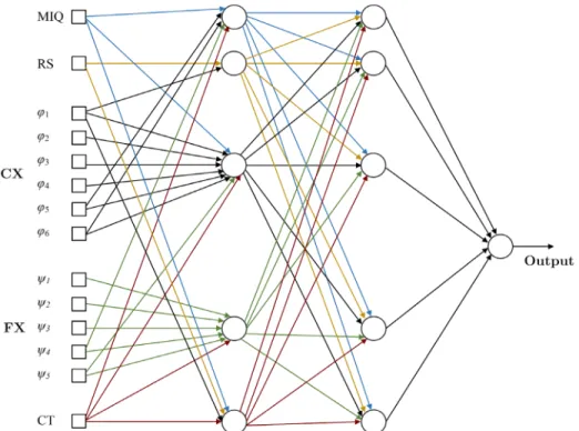
Figure 3-3: A fuzzy integral-based neural node where inputs are information sources and output is a fuzzy integral value. ... 32
Figure 3-4: A fuzzy integral-based neural network structure with three hidden layers ... 32
Figure 3-5: The structure of the fuzzy integral-based neural network with one hidden layer ... 35
Figure 3-6: Conceptual Design of a Mechatronic System based on MMP and Global Concept Score (GCS) ... 35
Figure 3-7: A Quadrotor drone in tracking and following mission using a visual servoing system. ... 36
Figure 3-8: An integrated visual servo control for a Quadrotor system ... 37
Figure 3-9: Parts and Subsystems for generation design concepts ... 37
Figure 3-10: ITG model for (a) a position-based visual servoing (PBVS) scheme and (b) an image-based visual servoing (IBVS) scheme for a quadrotor system. ... 39
Figure 3-11: (a) A simulation model of a Quadrotor drone with a visual servoing system. Image feature trajectories in (b) concept 4: Monocular IBVS with LQR controller, (c, d) concept 3: Stereo IBVS with PID controller. ... 47
Figure 3-12: Camera frame velocity in systems based on concept 4 (a) and concept 3 (b). ... 48
Figure 3-13: Image feature errors in systems based on concept 4 (a) and concept 3 (b). ... 48
Figure 4-1: Process of concept evaluation in design ... 54
Figure 4-2: Mechatronic Multicriteria Profile (MMP) and all sub-criteria... 55
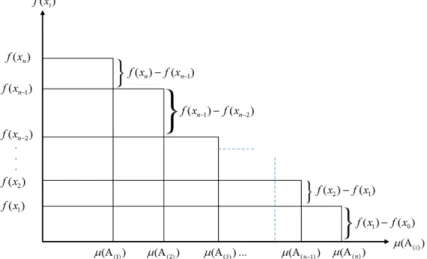
Figure 4-3: Graphical illustration of Choquet integral ... 57
Figure 5-1: Quadrotor model coordinate system ... 82
Figure 5-2: UAV Quadrotor control structure consisting of attitude motion control and visual servoing control ... 85
Figure 5-3: Model of the parallel stereo vision system observing a 3D point ... 87
Figure 5-4: Process of concurrent Mechatronic system design adopted from [153] ... 89
Figure 5-5: The simulation model of the vision-guided Quadrotor system ... 94
Figure 5-6: The step-response of the attitude and altitude control systems based on the final system-level optimization results ... 97
Figure 5-7: Position tracking performances based on results from (a) iteration 2 and (b) iteration 4, and a comparative graph of paths for a complete motion. ... 99
Figure 5-8: Visual feature errors from (a) iteration 2 and (b) iteration 4. ... 100
Figure 6-1: Three most common neighborhood topologies used in particle swarm optimization 106 Figure 6-2: Cascade Choquet integral-based aggregation on subsystems objective functions ... 111
Figure 6-3: The inertial and body frames of the quadrotor system ... 114
Figure 6-4: Quadrotor body structure and corresponding masses in x-y plane ... 114
Figure 6-5: UAV Quadrotor control structure consisting of flight motion control and visual servoing system ... 121
Figure 6-6: Quadrotor control system for attitude and position ... 122
Figure 6-7: Quadrotor PID Controller ... 122
Figure 6-8: Open Loop Block Diagram ... 124
Figure 6-9: Quadrotor complete position, attitude and altitude control scheme ... 124
Figure 6-10: Model of the parallel stereo vision system observing a point in 3D space ... 126
Figure 6-11: Forces acting on quadrotor arm as a cantilever beam ... 128
Figure 6-12: Natural Frequency Modes of a Cantilever Beam [191] ... 128
Figure 6-13: Step response properties of flight control system ... 132
Figure 6-14: The structure of AR. Drone 2 as the benchmark system for case study of the proposed detailed design process ... 134
Figure 6-15: Functional Dependency Tables (FDT) for: (a) System design objectives, (b) design constraints. ... 136 Figure 6-16: Quadrotor simulation model in test scenario where it tracks and intercepts a target
... 141 Figure 6-17: Step response results for attitude and altitude control system obtained from original AR. Drone ... 141 Figure 6-18: Step response results for attitude and altitude control system obtained from: (a) PSO optimization results with swarm size of 𝑛𝑛 = 100 with maximum iterations of 𝑇𝑇𝑇𝑇𝑎𝑎𝑇𝑇 = 200, (b) PSO optimization results with swarm size of 𝑛𝑛 = 500 with maximum iterations of 𝑇𝑇𝑇𝑇𝑎𝑎𝑇𝑇 = 1000. ... 142 Figure 6-18: Tracking error results for the visual servoing system obtained from: (a) PSO
optimization results with swarm size of 𝑛𝑛 = 100 with maximum iterations of 𝑇𝑇𝑇𝑇𝑎𝑎𝑇𝑇 = 200, (b) PSO optimization results with swarm size of 𝑛𝑛 = 500 with maximum iterations of 𝑇𝑇𝑇𝑇𝑎𝑎𝑇𝑇 = 1000. ... 143 Figure 6-19: Image feature trajectories for the visual servoing system obtained from: (a, b) PSO
optimization results with swarm size of 𝑛𝑛 = 100 with maximum iterations of 𝑇𝑇𝑇𝑇𝑎𝑎𝑇𝑇 = 200, (c, d) PSO optimization results with swarm size of 𝑛𝑛 = 500 with maximum iterations of 𝑇𝑇𝑇𝑇𝑎𝑎𝑇𝑇 = 1000. ... 144 Figure 6-20: Main frame translational velocity components during the object tracking process,
obtained from: (a) PSO optimization results with swarm size of 𝑛𝑛 = 100 with maximum iterations of 𝑇𝑇𝑇𝑇𝑎𝑎𝑇𝑇 = 200, (b) PSO optimization results with swarm size of 𝑛𝑛 = 500 with maximum iterations of 𝑇𝑇𝑇𝑇𝑎𝑎𝑇𝑇 = 1000. ... 145 Figure 7-1: Proposed mechatronic design roadmap based on the research contributions and
developments in various design phases... 147 Figure 7-2: Research sub-objectives covered in this thesis... 148
LIST OF ABBREVIATIONS
RTB Real Time Behaviour
Non-RTB Non-Real Time Behaviour
RTP Real Time Parameter
Non-RTP Non-Real Time Parameter
SO Sub-Objective
DFC Design for Control
MDQ Mechatronic Design Quotient
BG Bond Graph
GP Genetic Programming
FBS Function-Behavior-State
MDI Mechatronic Design Indicator
NLDOP Nonlinear Dynamic Optimization Problem
UML Unified Modeling Language
SysML Systems Modeling Language
DEE Design and Engineering Engine
MDO Multidisciplinary Design Optimization PIDO Process Integration Design Optimization
LSC Live Sequence Chart
RBP Requirements-based Programming
MCDM Multi Criteria Decision Making MMP Mechatronic Multicriteria Profile MIQ Machine Intelligence Quotient
DFG Data Flow Graph
ITG Intelligent Task Graph
FTA Fault Tree Analysis
FMEA Failure Modes and Effect Analysis
PN Petri Net
DSM Design Structure Matrix
ANN Artificial Neural Network
IBVS Image-based Visual Servoing PBVS Position-based Visual Servoing
LQR Linear Quadratic Regulator
DTM Design Theory and Methodology
UAV Unmanned Aerial Vehicle
UQH Unmanned Quadrotor Helicopters
COG Center of Gravity
PSO Particle Swarm Optimization
LIST OF APPENDICES
APPENDIX A IMPROVEMENTS ON CONCEPTUAL DESIGN OF MECHATRONIC SYSTEMS USING A FUZZY-BASED APPROACH ... 169
CHAPTER 1 INTRODUCTION
1.1 Background Information and Problem Definition
Mechatronic systems, as a combination of cooperative mechanical, electronics and software components with the aid of various control strategies (Figure 1-1), have led the engineering design into a new era by integrating the most advanced technologies with the best design schemes [1]. Design of a wide variety of products such as transportation systems, aircrafts, construction machines or even home appliances are now considered within the area of mechatronic systems. Mechatronic systems are often highly complex, because of the high number of their components, their multi-physical aspect and the couplings between the different engineering domains involved [2].
Generally, a systematic and multi-objective thinking method to mechatronics design is ideally needed due to the complexity of interactions between the subsystems. Design of mechatronic devices includes two major steps: conceptual design and detailed design. In the conceptual design phase, a complete and consistent listing of the requirements and behaviors is required as well as a thorough identification of critical parts of the solution that affects the overall performance. Then in detailed design phase, those candidate solutions that meet the requirements should be identified and provide the level of needed performance.
Designing a mechatronic product ideally needs an integrated and concurrent approach to achieve the following goals [3, 4]:
• Increased reliability; • High controllability; • Reduced complexity
• Better component matching; • Increased efficiency;
• Proper cooperation with other systems; • Increased flexibility
• Reduced effective cost;
• Facilitated system integration;
To achieve the above goals a concurrent and integrated design approach is ideally required. Although, due to lack of a systematic approach, design engineers in various industries still prefer to use traditional and sequential design methods.
Suh [5] suggested to define an engineering design process as a mapping from a requirement space consisting of behaviors, to a structural parameter space. To gain insight into the design of a mechatronic system, Li et al. [6] suggested dividing the requirement space into two subspaces which represent: Real-time behaviors (RTBs) and Non-real-time behaviors (Non-RTBs). Following this division of the requirements, system parameters in structural space can also be divided into two subspaces as: Real-time (or controllable) parameters (RTPs), and Nonreal-time (or uncontrollable) parameters (Non-RTPs). Here, “real-time” corresponds to parameters, specifications and behaviors that are changeable in a timely manner after the machine is built. Controller gains, accuracy and speed are some examples of RTPs and RTBs. On the other hand, “Non-real-time” parameters and specifications are the ones that can be hard to alter after the machine is made, either because it would be costly to change them or they are inherently unchangeable at this stage. Structural material, dimensions, weight, and workspace can be considered as Non-RTPs and Non-RTBs. Traditional methodologies for mechatronic systems design consisted of sequences of the real-time and non-real-time requirements rather than a concurrent design process (Figure 1-2a).
As a typical example in the design of traditional controllable machines, a robot manipulator can be pointed out. At the beginning of such a traditional design scenario, Non-RTPs are designed based on the Non-RTB specifications. This process itself includes designing the mechanical structure and then adding electrical components. The mechanical structure (e.g., configurations, dimensions, layout of actuators and sensors, etc.) is first determined based on the requirements in the Non-RTB space (e.g., robot workspaces, maximum payloads, etc.). Subsequently, RTPs (e.g., controller algorithm and parameters, signal conditioning) are determined based on RTB specifications (e.g., desired path, speed, accuracy, stability) to control the already established structure.
Recent progresses in control engineering and computer science have created a misconception in design community that the design of the structure and electrical hardware can be considered to be no longer the main design aspect in some cases and the inadequacies of the system mechanics could be compensated by some high performance state-of-the-art control schemes. One can easily criticize this thinking because a perfect control strategy may be very hard to achieve due to hardware limitations and dynamic interactions, regardless of the effort devoted to the design of the controller system. However, this does not imply at all that the performance of an electro-mechanical system cannot be improved by better control strategies. It is the design process “optimality” that is in doubt and question.
In a concurrent model for mechatronic systems design (Figure 1-2b), both RTBs and Non-RTBs should be considered simultaneously for realization of RTPs and Non-RTPs. In a common mechatronic system, the system performance which is the real-time and nonreal-time system behaviors (RTBs and Non-RTBs) explicitly relies on the design of its control algorithm and parameters (RTPs) and also the design of the mechanical structure (Non-RTPs). More specifically, the design specifications for controller and limitations should be considered in the design of the mechanical structure and in the considering the alternatives for the electrical hardware. In addition, unlike in a traditional design, controllability and programmability of RTPs should be considered as an opportunity to further improve the design after the machine is built.
(a)
(b)
Figure 1-2: Model of Mechatronic design. (a) Traditional sequential design (b) Concurrent design adapted from [6]
1.2 Research Scope and Objectives
The importance of mechatronic systems in engineering has been increasing in past decades as they are able to perform very complex tasks with various applications. Design of mechatronic systems concerns the integration of several disciplines where mechanics are combined with electronics, control, software, hydraulics, aerodynamics, etc. This inherent complexity of product development and consequently its multi-domain integration, make it difficult for design engineers to understand mechatronics systems as one whole. Furthermore, being multi-criteria problematic, design of mechatronic systems tends to deal with Pareto decisions. Therefore, achieving optimal or near optimal design solutions is a very complex if not impossible task, especially without identification of the performance parameters involved and a good level of understanding of their co-influences. It is therefore vital to take into account interactions between system requirements.
Hence, this thesis aims at answering the following research question: How to systematically use design criteria and parameters as well as their interactions to formulate an integrated solution to evaluate and optimize mechatronic system designs?
In this research work, the main objective is therefore to develop a systematic, concurrent and integrated approach which will support the design of a wide range of mechatronic systems. From this objective, four sub-objectives emerge;
Although mechatronic systems design is commonly recognized to deal with an important issue in terms of finding the right criteria to evaluate and synthesize designs, there is still no systematic approach to support this. Thus, as an early research concentration, the first sub-objective (SO) of this work is:
SO1: Identify and quantify a set of most-common yet highly effective criteria for mechatronics design.
In early phases of design i.e. product architecture and conceptual design, a number of challenges are faced by designers with regards to the selection of system components and choosing between various schemes and approaches for software and control system developments. Due to the lack of a multi-criteria overview of the mechatronic systems design, designers usually choose the seemingly most available and feasible components fitting their design requirements. Although they merely fulfill a functional design, but not necessarily an optimal one. Therefore, the second sub-objective is:
SO2: Develop a decision support framework for conceptual design of mechatronic systems to properly define performance criteria and provide information about their co-influences and their collective effect on the design optimality.
After obtaining an “elite set” of the design alternatives and architectures from conceptual design, it is generally time to extend the multicriteria thinking from previous sub-objective to the preliminary and detailed design phases where the design engineers deal with numbers, values and parameters with regards to each subsystem and their corresponding design objectives. Hence, the third sub-objective is:
SO3: Develop a multicriteria design solution, flexible enough to be applicable to both preliminary and detailed design phases.
With the intention of helping the designers with incorporating the developed design supports and methodologies into their projects, a fourth sub-objective rises as follows:
SO4: Provide guidelines to facilitate the use of the decision analysis and optimization tools. SO4 will ultimately help attain the right preferences and settings used in mathematical models of the design methodologies and system integrations.
It is important to note that the present thesis does not address the problem of developing a unified software platform capable of automated synthesis and evaluation for mechatronic system design, however the implemented models and functions are collected as a MATLAB toolbox to be published under a free license agreement. All the presented case studies are based on mathematical models of the physical components and their dynamic behavior. No experiments have been performed, but some of the models have been verified against data of commercially available products and components using computer simulations. Furthermore, to limit the scope of the present research, no major study, analysis and development have been carried out with regards to the optimization and decision making tools used in design methodologies.
1.3 Manuscript Outline
A literature review on mechatronics design methodologies and challenges is presented in Chapter 2. In Chapter 3, the new Mechatronic Multi-criteria Profile (MMP) is introduced for the purpose of concept evaluation in mechatronic systems design and the assessment procedures for each of its elements are described. Moreover, three different methods for decision support and aggregation based on fuzzy sets in the presence of interacting criteria are also presented in this chapter along with a case study of conceptual design of a vision-guided quadrotor UAV. In Chapter 4, four methods for identification of fuzzy capacities and parameters used in multicriteria design are introduced and exemplified. Chapter 5 is dedicated to the study and analysis of the “Design-for-Control (DFC)” approach for preliminary design of mechatronic systems. A design case study on the same quadrotor system is also presented in this chapter to provide us with more insights about advantages and disadvantages of using the DFC approach. In Chapter 6, we discuss a method for detailed design where we have embedded fuzzy information into a particle swarm optimization process for the sake of incorporating multi-criteria and multi-objective design problems. The conclusion of this thesis and the proposed future works are presented in Chapter 7. The references cited in this thesis are sorted in the bibliography section.
CHAPTER 2 LITERATURE SURVEY
The design of mechatronic systems is a direct result of intensive collaboration between engineers of the mechanical, electronic, control, and software domains in a design team which aims to attain product-related advantages, which are not feasible through mono-disciplinary efforts. The multidisciplinary nature of a mechatronic systems increases the complexity of the design task and requires special attention to product and design activities dependencies. In this chapter, a survey on the available literature is carried out to review the most common challenges faced by the designers during various phases of mechatronic design. We then explore the research efforts and standardized solutions/tools found to address these problems.
2.1 Mechatronic Design Challenges
In order to improve the development of solutions for mechatronic designers, identifying and understanding the challenges related to the design of mechatronic products is essential. Both academic and industrial sources have reported many challenges related to the design and development of mechatronic systems. Table 1-1 lists these challenges (from A to M) and the design stages they may appear in, and also the related work that have been performed to identify and/or solve the problems. By examining these challenges, five main types of challenges can be identified, which influence many of the problems in the development of mechatronic systems. These main categories are: 1) Design Methods, 2) Design Tools, 3) Design Support, 4) Human Factors, and 5) Control Software.
2.1.1 Design Methods
During past decades, many endeavors has been carried out to ideally form a reliable and comprehensive design framework for mechatronic systems, but it can be inferred that this goal has not been achieved yet [7]. It has been reported that still in many industrial projects, traditional methods with a sequential flow of activities are the main engineering design guideline [8]. The sequential approaches separate the design operations in the sense that some design activities require the information resulted by the design of the other domains. These approaches have proven to be unsuitable due to their lack of flexibility, and their inefficiency towards a concurrent design which increases the cost and development time [4].
Table 2-1: Most common challenges in mechatronic system design and related publications # Type Design Stages Challenges Pre lim in ary C onc ept ua l D eta ile d De si gn P os t P roc es si ng & Related Work A D es ign M et hod
s Requirement handling and traceability [11] [12] [13] [7] [9] [10] B Synchronizing the designs from different disciplines to attain concurrent engineering [14] [15] [13, 16] [17] C System complexity as a generic problem [14] [18] [12] [5] [19] D Exchange of design models and information between domains [15] [20] [11] [21] [22] E D es ign T ools
Model consistency and interoperability [23] [24] F Lack of tools and methods supporting multi-disciplinary design [25] [26] [9] [24] G A lack of a common language to represent a concept and overall system design [27] [9] [28]
H Design Integration [27] [25] [23] [26] [9] [29] I D es ign Sup po rt
s Early evaluation, testing and verification
[30, 31] [32-34] [35, 36]
J Support for decision making [30, 31] [35, 36]
K Difficulty in assessing the consequences of choosing between two alternatives [37] [38] [30, 31]
L H um an F act
ors Cooperative work, communication and interaction between engineers from different disciplines [15] M Con tr ol Sof twa
re Design support for generation of a control software [32] [24]
In a concurrent approach, all phases of the life-cycle of the product are considered as early as possible in the design [39]. This is a challenging task when dealing with complex design situations, where strong interdependencies might have unpredicted effects on the overall system performance [6]. A number of research works have suggested to ideally build the system by assembling single-domain subsystems and by focusing more on the design of interfaces among them [15, 39]. Therefore, research on mechatronics should also focus on the interactions of the different engineering disciplines rather than only on the interactions between the subsystems that are being designed [15]. Moreover, a concurrent method should be ultimately utilized to deal with the interactions between designers and their designs since it facilitates early detection of possible problems.
2.1.2 Design Tools
Nowadays, different tools are devoted to managing design data within the design disciplines. However, the lack of tools capable of integration and sharing the design data is still one of the main challenges in mechatronics design and development [40]. In a multidisciplinary design project, designers from different domains employ specialized tools. Examples are tools like SolidWorks [41] in the mechanical design domain, OrCad [42] in the electrical domain, and MATLAB [43] in the control domain. Furthermore, there are not many specialized tools that support the conceptual and preliminary stages of design and which are also capable of extension to the subsequent phases [20]. These domain-specific tools perform quite well within their own domain, but handling information from other domains is quite rare among them. Although, the tools used in design of the control systems and interfaces are usually more flexible as they use mathematical models, mostly as block diagrams or bond graphs, as modeling bases [23, 25].
Consequently, several problems towards system integration arise when using domain-specific tools in a multi-disciplinary design activity. For example, in mechanical design tools, the main focus is on the physical aspects of the product while providing abstract concepts and categorizing parts and elements based on other non-physical criteria are rarely applicable. Moreover, in control design tools, an abstract of the physical system is often used. Thus, it becomes difficult to find the explicit connection between all the system behavior and their corresponding physical actors. In electronic systems design tools, only predictions of electrical and logical behavior are supported, while the physical implementation of the control algorithm is often overlooked. Finally, in requirement management tools, most of the focus is on representing documented requirements
information. The inter-connection to other design domains is mainly made through reports, and it is the designer’s responsibility to connect such documents with the available design data.
2.1.3 Design Support and Decision Aid
The decisions of system designers immensely influence the evolving mechatronic product design concepts [26], thus, support for decision making is of high importance. During different stages of design, different questions are answered about the product at different levels of abstraction and detail. The resources being spent in finding effective answers to define how well and how efficiently decisions are being made. The main goal is ideally making better decisions as early as possible while utilizing less resources. Success in this requires support that based on predictions, provides a good comparison of what is gained or lost by making a certain design choices and alternatives.
Another considerable challenge in mechatronic design is towards design evaluation and interdisciplinary verification. The four classical verification methods are demonstration, test, inspection, and analysis [9]. Among these four methods, the first three require physical prototypes, while the latter requires mathematical models of the system and its interconnections. Developing appropriate models for analysis and a platform to verify various aspects of the system, including control system, is a place for additional challenges. In practice, specific models are developed to perform tests at different stages of design. Due to the use of domain-specific modeling tools, such models usually correspond to a specific point of view on the system. With the expected synergetic effects that characterize mechatronic systems, these separate views cannot capture the overall system behavior. Moreover, the analysis of different operation modes of the system, requires reconfigurable multi-domain models, which are seldom supported.
In early design activities, it is needed to select the system components and choose between alternatives for software and control strategies. This part of conceptual and preliminary design is usually known as choosing the “Elite Set” which includes a number of feasible yet efficient design alternatives. Without sufficient multi-criteria support, this practice always faces a number of problems and limitations [44]. In such cases, engineers tend to choose the first and the best components from what they see as available and feasible to meet their design requirements. Such decisions can optimistically lead to a functional design, but rarely to an optimal one. This problematic decision making generally occurs due to ill-defined performance criteria and lack of knowledge about the co-influences between criteria and the functionalities expected to be provided by neighbouring disciplines.
2.1.4 Human Communication and Cooperation
Human communication and cooperation is an important additional factor that influences the design integration of the mechatronic system. The issues within this challenge can be categorized as:
• Communicating the goals and design requirements and relating them to the chosen solutions. • Decomposition of the requirements and to facilitate monitoring them throughout the design
process.
• Building an information exchange platform to notify the designers about the influence of their solution on other parts.
All the mentioned issues strongly relate to the fact that there are currently very few methods and tools that support design activities from a system engineering point of view and facilitate the exchange of information between designers.
2.1.5 Control Design Software
Modern control system design tools such as MATLAB/Simulink [43], Maple [45] and LabView [46] provide means to translate control algorithms, in the form of block diagrams and state transition diagrams, to executable codes. The mentioned tools are just capable of transforming the model descriptions into control algorithms and codes. Generating codes from a block diagram or a logical and structural description from the Unified Modeling Language (UML) [47] is part of what is known as model-based software development. A limited number of industries use this approach for design of mechatronic systems and it is not a very common practice [40]. To reach a formal control description that can be transformed into codes and algorithms, the designer must define a control approach, and consider the implementation of functions for the signal measurements or filtering used for the control system outputs to the overall system. Once the control structure and strategy are chosen, design rules and optimization routines can be employed to determine the controller parameters, if the requirements are given in a suitable form. These requirements must be derived by the system experts first, as they are usually specified at a higher level of abstraction. There is still a considerable gap towards supporting and automating the control system design activities in the early stages of mechatronic design.
2.2 Available Solutions to Design Challenges
Many efforts from industries and researchers in academia have come up with methods and tools to deal with the challenges identified above. In this section, a group of these solution methods and tools are discussed.
2.2.1 Design Methods
As previously mentioned, the traditional design methodology in mechatronics usually decomposes the overall system into several sub-systems according to some practical considerations and a unique guideline is used for each design aspect, to design the system sequentially. This method does not consider couplings and inter-connections. When more than one criterion is required in the design process, which happens quite often, the decision making about the components and subsystems becomes very tedious. For complex and multi-disciplinary designs requiring a significant amount of time and optimality, an algorithm which directly leads to the best efficient solutions is needed.
Following the concurrent design concept, Zhang et al. [48] proposed an integrated approach for mechatronic design of a programmable closed-loop mechanism. They used an objective function to minimize the shaking force and moment and consequently to facilitate the design of the control system. As an improvement to this work, Li et al. [6] developed a concurrent design framework known as design for control (DFC). They stated that although control parameters could be changed after the machine is built, they should be designed simultaneously with the structural parameters to ensure system integration. To facilitate controller design, the reduction of the shaking forces and moments of the actuators, was the only objective considered in their method. Although they suggested an effective concurrent approach, but improving the system performance using changeability of the controller parameters was overlooked.
De Silva [49] discussed that in a sequential design approach for mechatronic systems, optimal design of subsystems does not necessarily provide the optimum overall configuration. He proposed to associate performance indices to the mechatronic subsystems within an indicator index, called “mechatronic design quotient (MDQ)” and maximizing this index after integrating all the subsystems. Following this method, Behbahani [50] proposed a formal methodology for design of mechatronic systems by using the concepts of mechatronic design quotient (MDQ), where links between design criteria have been taken into account by using fuzzy sets. The MDQ methodology was implemented in pilot projects and has proved to be efficient; however, measurement and
determination of criteria for design are more qualitative and no systematic assesment approach has been suggested. Aiming at performance evaluation in conceptual design, Ferreira et al. [51] proposed a neural networks-based decision support to recommend design solutions based on earlier successful designs. Similarly, Hammadi et al. [52] defined a multicriteria performance indicator as a neural network of radial basis functions for early stages of mechatronic design. However, both of these approaches did not include a proper modelling for correlation between objectives and also sub-domains. Furthermore, these endeavors did not support any extension to stages of detailed design.
Villarreal-Cervantes et al. [53] proposed a concurrent design methodology to formulate the mechatronic design problem of a parallel robot. They incorporated a nonlinear dynamic optimization problem where both kinematic and dynamic behaviors were considered to minimize a performance criterion. Their method avoids a recursive design approach and enables the designers to obtain a set of optimal parameters in only one design step. Despite the benefit of abstraction in the design process, their method did not include a systematic approach for design and also did not cover early stages of design.
Due to their explorative power and flexible design representation, evolutionary algorithms are widely used in design synthesis methods during the past decade. These algorithms are usually embedded into an optimization problems regarding certain design objectives. In an automated design framework proposed by Xu et al. [54], designs were generated according to various design objectives and constraints.
In order to automate the design generation of mechatronic systems, Seo et al. [36] proposed to combine bond graph (BG) modeling with Genetic Programming (GP). Even though their method has been successfully applied to the detailed design of a mechatronic system but it was more focused on the structural part of the design rather than control. Also, early stages of design were not supported in their approach. Similarly, Behbahani and de Silva [55, 56] have used GP and BG for identification of the topology and the parameter values of a mechatronic system while Hu et al. [57] have applied BG and GP for automated synthesis of mechatronic systems. Although, all the case studies presented were limited to time-driven systems. Since most mechanical systems involve both continuous and discrete dynamics, enabling the evolution of hybrid systems can result in increase of the design complexity.
Various authors have proposed using models that contain functional descriptions of systems, such as Function-Behavior-State (FBS) [10], Functional Representation [18] and MACE [18], to
track and improve choices made in early design phases. These models usually provide proper representations about the functions of the system as well as all the hardware and software components involved in each system functionality. In other approaches, functional flow and block diagrams are used where functions are modeled as transformation procedures of matter, energy, or information [13, 16]. The IDEF0 method [17] is an example of using functional flow diagrams, which provides a vast formalization. FunKey [58] method proposes allocating budgets of resources to the functions of a system to provide a good documentation of the architecting process and a means to compare product architectures. However not all the aspects and design criteria are considered within this approach. The implementation of these methods is also a challenging task. Furthermore, functional descriptions are mainly used to help the designers to identify related information, but not to classify or identify such information with the help of an automated system. Additionally, requirements information is not included in most of these methods. Suh et al. [5] presented an axiomatic design method, where they discussed that functional independence of the system components leads to an optimal design. To attain this, the method provides guidelines, namely, the axioms of independence and information, to compare and evaluate early design choices. They reported multiple situations where their method was successfully implemented and used [5]. Although, according to modern functionalities of mechatronic devices and products, a tight integration of subsystems is desirable, which is very hard to achieve through an approach based on functional independence.
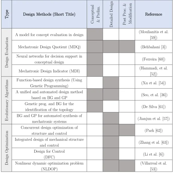
The above discussions about the available design methodologies to support concurrent mechatronic design are summarized in Table 2-2.
Table 2-2: Summary of recent methods in concurrent and integrated mechatronic design
T
ype Design Methods (Short Title)
Co nc ept ua l & P re lim . D et aile d D esig n Pos t P ro c. & Mo di fic at ion Reference D esig n E va lua tio
n A model for concept evaluation in design
(Moulianitis et al. [59])
Mechatronic Design Quotient (MDQ) (Behbahani [3])
Neural networks for decision support in
conceptual design (Ferreira [60])
Mechatronic Design Indicator (MDI) (Hammadi, et al. [52])
Ev olu tio na ry A lg or ithms
Function-based design synthesis (Using
Genetic Programming) (Xu et al. [54])
A unified and automated design method
based on BG and GP (Seo, et al. [36])
Genetic prog. and BG for the
identification of the topology (De Silva [61])
BG and GP for automated synthesis of
mechatronic systems (Jianjun et al. [57])
D esig n O pt imiz at io
n Concurrent design optimization of structure and control (Park [62]) Integrated design of mechanical structure
and control (Zhang et al. [63])
Design for Control
(DFC) (Li et al. [6])
Nonlinear dynamic optimization problem (NLDOP)
(Villarreal et al. [53])
2.2.2 Design Tools
Citherlet et al. [21] stated that there are mainly four different approaches to multi-disciplinary tool integration for the design of mechatronic systems: stand-alone, interoperable, linked, and integrated programs. Stand-alone programs are not desirable, as the tools are unrelated and the flow of information is not always possible. Interoperable programs are able to exchange or share models. Coupled tools are able communicate at run-time. Due to the flexibility of their modeling functionalities, some tools used in the control systems domain have taken this third approach.
Finally, integrated programs facilitate work in different domains within a single tool. Numerous CAD tools, have chosen this approach and incorporated tools from other domains into their software suites. For example, the latest version of CATIA [19] also supports electronics system modeling, and supports embedded control code generation. The existing coupled and integrated programs predict the behavior of systems from a detail design viewpoint. However, establishment of a direct connection with information from earlier design stages is still missing.
Madelia [22] language possesses an advanced environment for modeling, simulation and prototyping of complex physical systems. It supports the exchange of simulation models and the development of simulation libraries. Modelica supports libraries of models and functions with design capabilities for multi-domain modeling, enabling the designers to combine electrical, mechanical, control, thermodynamics and hydraulics within a system. This tool is also capable of executing and analyzing design models through connecting Modelica models with external solvers.
The Unified Modeling Language (UML) is a standardized modeling language which originated from object oriented software engineering, and it is maintained by the Object Management Group (OMG)[28]. UML aims at describing and documenting systems, rather than simulating them. Thus, a new modeling language named Systems Modeling Language (SysML)[64] is produced which reuses a subset of UML functionalities and extends them to some new functionalities such as creating block diagrams and parametric diagrams. The SysML language is intended to model systems from a broad range of industry domains such as aerospace, automotive, energy or health care and mechatronics. A number of researchers have tried integrate the descriptive capabilities of SysML to other analysis and simulation tools [65].
MATLAB in combination with Simulink [43] is well established for technical computing, simulation and model based design in many engineering domains. Simulink is an extension of MATLAB, which allows user to create graphical models, without writing any code. In fact, Simulink has many different libraries, which cover different domains with physical modeling e.g. SimMechanics [66] toolbox, signal processing toolbox, rapid prototyping toolbox, etc. Using these toolboxes a strong co-simulation and design integration can take place in the MATLAB/Simulink environment as the basis for any mechatronic analysis. Simscape [67] is a tool for the design and simulation for multi-domain physical systems. The aim of Simscape is the modeling of systems as networks of physical components. It extends Simulink with libraries for modeling systems from mechanical, electrical, hydraulic, and other physical domains.
CORE [68] is another software which uses a model-based system engineering approach for system integration. This tool captures requirements through making models and functional decomposition and flows. The models provided by CORE can be related manually by the designers, outside the CORE tool where a framework based on SysML is available to integrate information from other modeling and simulation tools.
In support of multi-disciplinary design and optimization, a framework called the Design and Engineering Engine (DEE) has been developed by La Rocca [69]. DEE is a domain-independent tool suitable for the design of a variety of systems from multiple domains. Data sharing between the various tools is enabled by using an agent-based network [70].
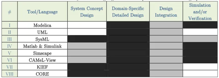
For the languages and tools used in design a multidomain systems such as mechatronic devices, an evaluation is summarized in a Table 2-3 by considering some key characteristics relevant to the development and design process for mechatronics. The cells shaded in black indicate whether the tool or language is suited for the specified criteria while the cells shaded in grey represent partly suited and the blank cells represent non-suitability.
Table 2-3: Evaluation Summary of the languages and tools per mechatronic design process
# Tool/Language System Concept Design Domain-Specific Detailed Design Integration Design
Simulation and/or Verification I Modelica II UML III SysML
IV Matlab & Simulink
V Simscape
VI CAMeL-View
VII KIEF
VIII CORE
2.2.3 Optimization and Design Support
To be able to optimize a multi-domain system, multidisciplinary design optimization (MDO) and process integration design optimization (PIDO) approaches are available [37, 71-73]. MDO is, as presented in [73], a methodology for the design of complex engineering systems that coherently exploits the synergism of mutually interacting phenomena. In other words, a MDO approach helps the process of design to decide what to change, and to what extent to change it, when everything influences everything else. In mechatronic design, optimizing domain-specific system performance indices require performing trade-off studies through multi-domain models. By finding the best
possible values for different properties through an optimization, the net objective or fitness function can be maximized. It is important for the designers to be able to make decisions in the right direction during all phases of product development. Thus, PIDO tools and an integration infrastructure are used concurrently to support the designers in taking the right actions.
2.2.4 Human Communication and Cooperation
In order to achieve an integrated design approach, it is of high importance to consider human factors and the communication between the people involved in the design of a system. Pahl et al. [74] have identified the communication and exchange of information between designers as one of the fundamental aspects of their systematic design approach. They mentioned methods like brainstorming and group evaluations to support the information exchange activities. They stated that these activities are helpful specifically in the conceptual phase. However, such methods cannot be appropriately extended to the later stages of design, because they have been intended to deal with less detailed information.
Unfortunately, despite the recognized importance of communication between design engineers and the exchange of information, there is still no formal tool supporting the design activity while considering the integrating of individual design contributions alongside an overview of the system and its goals.
2.2.5 Control Software
There are various commercial code generators available, both for unified environments such as Matlab/Simulink and also UML-based modeling tools such as SysML. Towards automation of the control design, requirements must be interpreted into control structure and logic in the early design phase. By using live sequence charts (LSC), it is possible to automatically derive control software logic and structure from requirements in the form of UML. To get from requirements to control software, a method based on requirements-based programming (RBP) is proposed by Rash et al. [75]. This method increases development productivity and the quality of the generated code by automatically performing verification of the software. A more functional connection between requirements and control software can be achieved using the functional block computer-aided design environment [60]. A prototyping tool can be used to design and analyze high-level control software components while generating run-time code for distributed control systems. Moreover, partial automation of the control development process is attainable through incorporation of pre-developed control codes from component-specific databases.
CHAPTER 3 ARTICLE 1: MULTICRITERIA DECISION SUPPORT FOR CONCEPTUAL DESIGN OF MECHATRONIC SYSTEMS; A
QUADROTOR DESIGN CASE STUDY
Abolfazl Mohebbi, Sofiane Achiche and Luc Baron
Submitted to Springer Journal of Research in Engineering Design, Jan. 2015
3.1 Abstract
Designing mechatronic systems is known to be both a very complex and tedious process due to the high number of system components, their multi-physical aspects, the couplings between the different domains involved in the product and the interacting design objectives. This inherent complexity calls for the crucial need of a systematic and multi-objective design thinking methodology to replace the often-used sequential design approach that tends to deal with the different domains and their corresponding design objectives separately leading to functional but not necessarily optimal designs. Thus, a new approach based on a multi-criteria profile for mechatronic systems is presented in this paper for the conceptual design stage. Additionally, in order to facilitate fitting the intuitive requirements for decision-making in the presence of interacting criteria, three different methods are proposed and compared using a case study of designing a vision-guided quadrotor drone system. These methods benefit from three different aggregation techniques such as Choquet integral, Sugeno integral and fuzzy-based neural network. It is shown that although the Sugeno fuzzy can be a useful aggregation function for decisions under uncertainty, but the approaches using Choquet fuzzy and fuzzy integral-based neural network seem to be more precise and reliable in a multi-criteria design problem where interaction between the objectives cannot be overlooked.
3.2 Introduction
Introduction of mechatronic systems was a direct result of an increased need for controlled and intelligent electromechanical systems with better performance, more flexibility and higher reliability capable of performing complex tasks. The process of designing a wide variety of products such as avionic systems, robots, transportation and construction machines or even home appliances