HAL Id: hal-01976690
https://hal.laas.fr/hal-01976690
Submitted on 10 Jan 2019HAL is a multi-disciplinary open access archive for the deposit and dissemination of sci-entific research documents, whether they are pub-lished or not. The documents may come from teaching and research institutions in France or
L’archive ouverte pluridisciplinaire HAL, est destinée au dépôt et à la diffusion de documents scientifiques de niveau recherche, publiés ou non, émanant des établissements d’enseignement et de recherche français ou étrangers, des laboratoires
Dependability Assessment of GUARDS Instances
Jean Arlat, Tahar Jarboui, Karama Kanoun, David Powell
To cite this version:
Jean Arlat, Tahar Jarboui, Karama Kanoun, David Powell. Dependability Assessment of GUARDS In-stances. 4th IEEE International Computer Performance and Dependability Symposium (IPDS’2000), Mar 2000, Chicago, United States. �hal-01976690�
4th IEEE International Computer Performance and Dependability Symposium (IPDS'2000), Chicago (USA), 27-30 mars 2000, pp.147-158
Dependability Assessment of GUARDS Instances
Jean Arlat, Tahar Jarboui, Karama Kanoun and David Powell LAAS-CNRS
7 avenue du Colonel Roche 31077 Toulouse Cedex 4 – France
E-mail: {arlat, jarboui, kanoun, dpowell}@laas.fr
Abstract
The generic architectural concepts developed in the framework of the European ESPRIT project GUARDS (Generic Upgradable Architecture for Real time Distributed Systems) provide a comprehensive framework from which specific instances can be derived to meet the dependability requirements of various application domains. Three main application domains are considered (railway, nuclear propulsion and space) that correspond to the fields of the three end-user partners of the project.
This paper presents the modeling method supporting the assessment of GUARDS instances. The goal is to assist the designers in making objective decisions for defining a specific instance from the generic architecture.
After a short summary of the main architectural concepts of GUARDS, the paper describes the major assumptions considered for the modeling that concern: i) component types (both hardware and software), ii) fault types, where special attention is paid to potentially correlated faults, and iii) the generic fault tolerance features of GUARDS. The main architectural characteristics of the target instances (one for each application domain) are briefly described. The modeling strategy is summarized and examples of models (stochastic Petri nets) are given. Selected results are then presented and discussed; they exemplify the usefulness of the modeling and evaluation method, in
1- Introduction
The development and validation of fault-tolerant computers for critical real-time applications are currently both costly and time-consuming in particular as a result of the very specialized, and often hardware-intensive solutions that are classically considered. To tackle these issues, a consortium of European companies and academic partners has been formed to design and develop a Generic Upgradable Architecture for Real-time Dependable Systems (GUARDS), together with an associated development and validation environment [1].
The end-user companies in the consortium currently deploy ultra-dependable real-time embedded computers in their systems, but with very different requirements and constraints resulting from the diversity of their application domains: railway, nuclear propulsion, and space systems. The overall aim of the GUARDS project is to significantly decrease the lifecycle costs of such embedded systems. The intent is to be able to configure instances of a generic architecture that can be shown to meet the very diverse requirements of these (and other) critical real-time application domains.
The project has carried out an extension set of validation activities, including formal verification, analytical modeling and fault injection (e.g., see [2], [3] and [4]). This paper focuses on analytical modeling work aimed at assessing the dependability of GUARDS instances. The goal is to assist the designers in making objective decisions for defining a specific instance of the generic architecture, a need that is exemplified by related work carried out on previous modular fault-tolerant architectures (e.g., see SIFT [5], FTPP [6] or Delta-4 [7]). An insightful effort tackling system-level modeling and sensitivity analyses was also reported in [8]. The novelty of the study reported here concerns i) the enhanced scope of the generic modeling effort where explicit attention has been paid to the various levels of the generic architecture and ii) the practical dimension of the target instances considered originating from three distinct applications domains.
Our main concern is to capture the appropriate level of detail of the architecture encompassing fault types, redundancy management policies and maintenance strategies, so as to be able to derive evaluation models suitable for carrying out extensive sensitivity analyses to support meaningful and clear design choices.
The modeling of large complex fault-tolerant systems is faced with the problem of mastering complexity and state explosion resulting from the large number of (hardware and software) components, and of the multiplicity and intricacy of their interactions. Several studies have been
using either approximate or exact solutions based on stochastic binary decision diagrams, stochastic Petri nets or Markov chains (e.g., see [11-16]). In this paper, in accordance with the genericity principle that led to the design of the GUARDS architecture, a generic modeling framework, inspired by the modular approach developed in [17], is considered.
Special attention has been paid to model the impact of common mode failures among the various redundancy dimensions of the architecture — whether these failures induced by hardware or by software faults [18] [8]. The models also take into account the coverage of the various embedded error detection mechanisms. This allows identification of a restricted set of parameters that are common to all instances, which makes it possible for their assessment to be carried out on a fair basis. The evaluation strategy relies on the use of stochastic Petri nets. The evaluation of dependability measures and sensitivity analyses were supported by the software package SURF-2 [19].
This paper extends a preliminary work published in [20]. The main extensions concern the provision of more detailed models and additional dependability measures. It is structured as follows. Section 2 sketches the main features of the generic architecture. Section 3 defines the modeling assumptions that elaborate on an abstract view of GUARDS architecture; it also identifies the components modeled, the fault types considered and the fault tolerance features exhibited by the generic architecture. The three target instances (railway, nuclear propulsion, and space) are then briefly described in Section 4. The modeling strategy is described in Section 5. Section 6 provides examples of evaluations and sensitivity analyses that can be carried out. Finally, Section 7 concludes the paper.
2- The GUARDS Architecture
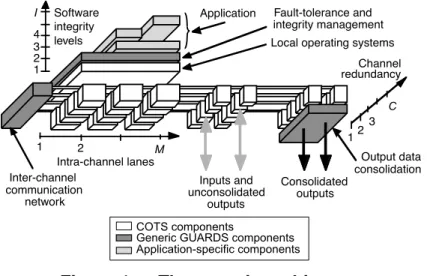
To cut development costs and cope with obsolescence, the GUARDS architecture favors the use of commercial off-the-shelf (COTS) hardware and software components, with application-transparent fault-tolerance implemented primarily by software. It uses a limited number of specific, but generic, hardware and software components to implement an architecture that can be configured into a wide variety of instances along three architectural dimensions — redundant channels, redundant lanes and integrity levels — that also form three dimensions of fault containment (Figure 1):
• Channels constitute the primary physical-fault containment regions. • Lanes form the secondary physical-fault containment regions.
COTS components Generic GUARDS components Application-specific components 1 1 2 3 2
Application Fault-tolerance and integrity management Inter-channel communication network Inputs and unconsolidated outputs Consolidated outputs Output data consolidation Software integrity levels Channel redundancy Intra-channel lanes
Local operating systems 4 3 I 2 1 M C
Figure 1 — The generic architecture
Channels provide the ultimate line of defense within a single instance for physical faults that affect a single channel. Fault tolerance is based on active replication of application tasks over the set of channels. It must be ensured that replicas are supplied with the same inputs in the same order, despite the occurrence of faults. Then, as long as replicas on fault-free channels behave deterministically, they should produce the same outputs. Error processing can thus be based on comparison or voting of replica outputs.
The lanes dimension can be used to improve the capabilities for fault diagnosis within a channel, e.g., by comparison of computation replicated on several nodes. There is also scope for improving coverage with respect to design faults by using intra-channel diversification. Alternatively, lanes can be used to improve the availability of a channel, e.g., by making passive a node that is diagnosed to be permanently faulty.
The integrity dimension aims to provide containment regions with respect to software design faults. The intent is to protect critical components from the propagation of errors due to residual design faults in less-critical components.
A particular instance of the architecture is defined by the dimensional parameters {C, M, I} (see Figure 1), a reconfiguration strategy, and an appropriate selection of generic hardware and software GUARDS components. These generic components implement mechanisms for:
• Inter-channel communication. • Output data consolidation.
The two dimensions of physical redundancy allow for a wide variety of instances to be defined with different fault-tolerance strategies. The management of system fault-tolerance and integrity is software-implemented through a distributed set of generic system components (shown as a “middleware” layer on Figure 1). This layer is itself fault-tolerant (through replication and distribution of its components) with respect to faults that affect channels independently (e.g., physical faults). Although the tolerance of design faults in this system layer was not explicitly, correlated faults are included in the models used to assess the dependability of instances of the architecture.
3- Modeling Assumptions
The models are based on an abstract view of the components and layers that compose the GUARDS architecture depicted in Section 1. We identify in this section the main components considered, the related fault types, and the fault tolerance features common to the three instances.
3.1- The Modeled Components
The aim is to model instances of the generic architecture and evaluate their behavior in the face of both physical and design faults. The granularity of the modeling is selected in terms of the possible effects of faults and the independence assumptions that can be made.
From the modeling viewpoint, the generic architecture can be described by four basic layers (Figure 2), which, from the bottom-up, are:
1.hardware layer: mostly off-the-shelf physical components, potentially affected both by physical faults and design faults;
2.executive layer: off-the-shelf operating systems on each processor;
3.system layer: GUARDS-specific components supporting the fault tolerance mechanisms;
4.application layer: end-user application programs — this layer is divided into sub-layers corresponding to the I integrity levels.
channel C channel 1 channel 2 lane 2 lane M nucleus hardware executive system application integrity level I integrity level 2 integrity level 1 lane 1
Figure 2 —Modeling viewpoint of generic architecture
The layers are partitioned horizontally to account for the two dimensions of redundancy included in the architecture:
1. a set of C channels,
2. a subdivision of each channel into: • a set of M lanes,
• a channel nucleus corresponding to its ICN manager, the ICN link by which it sends information to the other channels, its I/O interfaces, etc.
Since there is no explicit means to tolerate design faults affecting the executive and system software supported by the ICN manager, the channel nucleus is considered as a monolithic component from the modeling viewpoint.
An instance of the architecture is characterized by the values of C, M and I, and a corresponding
fault tolerance strategy (two instances of the architecture could have identical values of C, M and I, but
different fault tolerance strategies).
The fault tolerance strategies that are envisaged allow instances to be degraded by making passive channels, lanes or integrity levels. Therefore, the current configuration of an instance may be defined by a vector of three state variables, { ic, im, ii}, with:
• ic ∈ [1,C] indicating the current number of active channels (initially C),
• im ∈ [1,M] indicating the current number of active lanes (initially M),
• ii ∈ [1,I] indicating the current lowest active integrity level (initially 1).
3.2- Independent and Correlated Faults
Diversification across channels is not currently considered, so we will assume that fault rates of the various components are identical across channels.
The architecture considers both physical faults (that can only affect hardware, i.e., the nucleus and the hardware layer) and design faults (that can affect both hardware and software, i.e., the nucleus and any layer). Physical faults are assumed to occur independently on different components. Some design faults can also manifest themselves as if they were independent faults, even on identical components, if the pointwise conditions necessary for their activation occur independently on the different components (i.e., Heisenbugs [20]).
We therefore distinguish independent faults affecting the nuclei [ψN] and the faults affecting each
layer X of the processing part of the architecture [ζX(m)] where X ∈ {H, E, S, Ai} (hardware, executive,
system, integrity level i of the application).
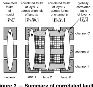
However, common-mode failures due to correlated design faults must also be considered. Here, we consider the following possible correlated faults (Figure 3):
1. channel correlated faults (i.e., across all lanes),
2. lane or nuclei correlated faults (i.e., across all channels), 3. global correlated faults (i.e., across all lanes and all channels).
correlated faults of nuclei channel C channel 1 channel 2
lane 1 lane 2 lane M
nucleus correlated faults of layer x across channels of lane m correlated faults of layer x across lanes of channel c globally correlated faults of layer x [α ] N [α ( m) X ] [β ( c) X ] [γ ] X
Figure 3 — Summary of correlated faults
“diagonal” correlated faults, since components are either common to all processors, or redundantly distributed across channels or lanes).
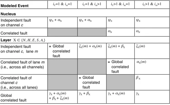
The notion of correlated faults depends of course on the particular configuration of the architecture. For example, there can be no “correlated” faults within a channel if the configuration only has a single lane. So, to be able to represent different configurations and compare different instances of the architecture on a common basis, attention has been paid to the identification of rates of independent vs. correlated faults. Table 1 depicts the respective impact of these parameters on the independent/correlated faults for various configurations.
Table 1 — Modeled events and relationship to basic fault rates
Modeled Event iC=1 & im=1 iC=1 & im>1 iC>1 & im=1 iC>1 & im>1
Nucleus Independent fault on channel c ψN + αN ψN + αN ψN ψN Correlated fault αN αN Layer X ∈ {N, H, E, S, Ai} Independent fault on channel c, lane m ≡ Global correlated fault ζX(m) + αX(m) ζX(m) + βX ζX(m)
Correlated fault of lane m (i.e., across all channels)
≡ Global correlated fault αX(m) Correlated fault of channel c
(i.e., across all lanes)
≡ Global correlated fault β X Global correlated fault γX + αX(m) + βX + ζX(m) γX + βX γX + αX(m) γX
3.3- Temporary and Permanent Faults
Faults can be classified as either temporary or permanent, according to whether or not their presence is related to particular point-wise conditions [21]. Fault treatment depends on whether the fault is diagnosed to be a permanent fault or a temporary fault, according to the conclusion of a self-test carried out on a channel after it has been isolated from the pool. If a fault is diagnosed to be permanent, an explicit repair action must be carried out, whereas in the case of a temporary fault, certain fault treatment strategies may authorize automatic re-integration of the faulty component.
Therefore, we need to be able to distinguish the proportions of faults that are temporary or permanent. To do so, we must consider whether the faults are independent or correlated, and whether they are of physical origin or due to erroneous design.
Independent faults of the nuclei or of the hardware layer may correspond to either physical faults or design faults. However, independent faults of the executive, system and application layers can only be design faults. Also, by definition, design faults leading to independent manifestations must be temporary faults, since their manifestation is related to point-wise system activity conditions. Consequently, for the nuclei and the hardware layers, we have considered the proportion of independent faults that are permanent as an important parameter of the model.
Correlated faults may be considered as either temporary or permanent, according to the fault treatment and maintenance policy that is adopted.
3.4- The Common Fault Tolerance Features
Besides the specific fault tolerance strategies inherent to each target instance, it can be assumed that the generic architecture supports a set of fault tolerance features that can be considered on a common basis. In particular, each channel has intra-channel or local mechanisms that provide error detection in addition to that provided by inter-channel error processing. The efficiency of the local error detection mechanisms depends on the corresponding error source (Nucleus, Hardware, Executive, System, integrity levels of the Application) and is characterized by coverage factors cX,
X ∈ {N, H, E, S, A1, A2}. Although in the analyses, we did not discriminate the application integrity
levels with respect to the efficiency of local error detection, they are distinguished in the modeling. Inter-channel error processing depends on the number of operational channels. As long as there are at least three operational channels, any errors due to a single faulty channel are assumed to be masked (and detected) by majority voting. In the case when two operational channels are available, a two-out-of-two vote is considered and single channel errors are assumed to be detected. Let the coverage of these assumptions be defined as cVc, where index c ∈ {2,3,4}. Since a 4-channel configuration is
capable of tolerating arbitrary faults, cV4 can reasonably be assumed to be 100%. The other coverages
should be considered non-perfect; for example, the non-coverage includes the case of a Byzantine fault leading to failure of the clock synchronization mechanism.
permanent or temporary. Let the execution rate of the self-test be defined as δ and let the coverage of the self-test with respect to permanent faults be defined as cST. If the fault is judged to be permanent, it is repaired with rate µ . If the fault is judged to be temporary, the channel is reintegrated with rate ρ . With probability 1-cST, a permanent fault is erroneously judged to be a temporary fault; in this case, we (pessimistically) assume that a catastrophic failure occurs. The permanent faults represent a proportion π of the independent faults affecting the nuclei and the hardware layer.
Any correlated faults, except those occurring at integrity level 1, are assumed to lead to a catastrophic failure1
. Correlated faults at integrity level 1 should be confined to that level by the integrity policy (IP) enforcement mechanisms. Let the coverage of these mechanisms be cIP. Detected violations of IP cause the incriminated layer to be discarded.
All undetected errors are assumed to lead to catastrophic failures.
4- The Target Instances
Three instances of the GUARDS architecture were modeled and evaluated. These were meant to match the prototypes being developed by each end-users according to the needs identified for their respective application domains: railway, nuclear propulsion and space.
4.1- The Railway Instance
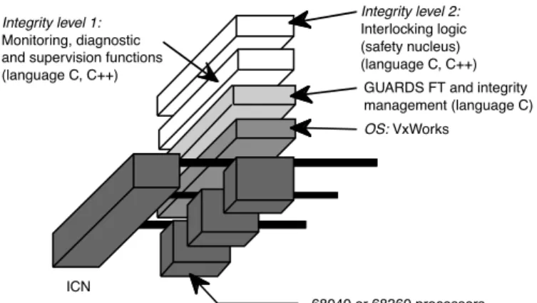
Figure 4 depicts the railway instance evaluated. It features Motorola 68040 or 68360 processors, each running a Posix-compliant VxWorks operating system.
OS: VxWorks Integrity level 1:
Monitoring, diagnostic and supervision functions (language C, C++) Integrity level 2: Interlocking logic (safety nucleus) (language C, C++) 68040 or 68360 processors GUARDS FT and integrity management (language C)
ICN
Compared to currently deployed systems, the innovative aspect of this architecture is the co-existence of two levels of application software of very different degrees of criticality:
1. the highly-critical interlocking logic or safety nucleus, which is at the highest integrity level, 2. the monitoring, diagnostic and supervision functions, which are of the lowest criticality.
This is a significant departure from current practice in railway applications, where these two levels of integrity would normally be implemented on separate instances. However, there is an appreciable economic advantage to be gained when it is possible to share the same hardware between both levels (e.g., for small railway stations).
As long as there are three operational channels, any errors due to a single faulty channel are assumed to be masked (and detected) by majority voting. While there are only two operational channels, the instance operates in a two-out-of-two mode. If a fault should occur while in this mode, the instance is switched to a safe state if the errors caused by the fault are detected (either locally within a channel or by two-out-of-two comparison).
4.2- The Nuclear Propulsion Instance
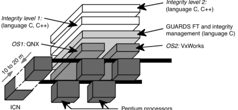
The targeted nuclear propulsion application is a secondary protection system. The prototype for this application is a 2-channel architecture with two Pentium processors in each channel (Figure 5). To prevent common-mode failures of both channels due to physical damage, the channels are geographically separated one from the other by a distance of 10 to 20 meters. Like the railway application, this instance hosts two levels of integrity.
An innovative aspect of this prototype is the use of two processors in each channel, with two different Posix-compliant operating systems: QNX and VxWorks. Apart from the operating systems, both processors run identical software to implement duplication-and-comparison within each channel. The aim is to be able to detect errors due to design faults in these commercial off-the-shelf operating systems.
All application software components are executed on both processors in both channels. Within a channel, the copies of an application component on lanes 1 and 2 are provided with the same inputs in the same order. In the absence of faults, both copies should provide identical results. These are compared by a bit-to-bit comparator implemented as a GUARDS system-level component [21]. All application components within a channel are thus configured as self-checking pairs to provide detection
In particular, this includes physical faults (of the processors) and design faults of the processors and their operating systems. Note that, in this instance, an assumption of independent activation for design faults of the operating systems can be based on the fact that their designs are diversified. For design faults of the processors, an assumption of independent activation can be based on their diversification of utilization (due to loose coupling and diversification of operating systems).
As long as both channels are operational, they operate in a two-out-of-two mode. Results of computations that are declared as error-free by the intra-channel mechanisms are compared and, in case of disagreement, the instance is put into a safe state. Let the coverage of the two-out-of-two vote be defined as cV 2. However, if errors are detected locally by intra-channel mechanisms, the channel declares itself to be faulty and the instance switches to 1-channel operation. Note that this strategy is different to that of the railway instance that has degraded to 2-channel configuration: in that case, the instance switches to a safe state whether the error is detected locally or by comparison.
10 to 20 m OS1: QNX Integrity level 1: (language C, C++) Integrity level 2: (language C, C++)
ICN Pentium processors
OS2: VxWorks
GUARDS FT and integrity management (language C)
Figure 5 — Nuclear propulsion target instance (C=2, M=2, I=2) 4.3- The Space Instance
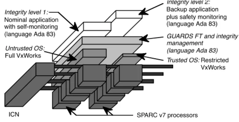
The instance considered for space applications is the most complex of the three prototypes. It is a full 4-channel instance of the architecture capable of tolerating arbitrary faults at the inter-channel level (Figure 6). Degradation to 3-, 2- and 1-channel operation is possible. As for the railway and nuclear applications, this instance also features two levels of integrity.
Trusted OS: Restricted VxWorks Integrity level 1: Nominal application with self-monitoring (language Ada 83) Integrity level 2: Backup application plus safety monitoring (language Ada 83)
SPARC v7 processors
GUARDS FT and integrity management
(language Ada 83)
ICN
Untrusted OS:
Full VxWorks
Figure 6 — The space target instance (C=4, M=2, I=2)
Like the prototype for the nuclear propulsion application, this instance also possesses two lanes, but for a different reason. However, for the nuclear instance, the aim was to allow diversified but equivalent operating systems to be used so that errors due to design faults could be detected. Here, the objective is to have one of the lanes act as a backup for the other lane.
We refer to the two lanes as the primary and secondary lanes. Each lane supports a different operating system and different application software:
1. The primary lane runs a full-functionality version of VxWorks and a nominal application that provides full control of the spacecraft and its payload. The application includes built-in self-monitoring based on executable assertions and timing checks.
2. The secondary lane runs a much simpler, restricted version of VxWorks and either a safety-monitoring application or a simple back-up application. The purpose of the latter is to provide control of the spacecraft in a very limited “survival” mode (e.g., sun-pointing and telemetry/remote functions).
The idea is that neither the full VxWorks nor the nominal application supported by the primary lane can be trusted to be free of design faults. However, the restricted version of VxWorks and the application software supported by the back-up lane are assumed to be free of design faults and thus trustable. The aim is to allow continued (but severely degraded) operation in the face of a correlated fault across all processors of the primary lane. Errors due to such a correlated fault can be detected in two ways:
• self-monitoring functions included within the nominal application,
• a safety-monitoring application executed by the secondary lane while the primary lane is operational.
In view of the differing levels of trust of the applications supported by the primary and secondary lanes, they are placed at different levels of integrity. The nominal application (on the primary lane) is not trusted, so it is assigned to integrity level one. The back-up application is assumed to be free of design faults and is placed at integrity level two. This separation of the integrity levels on different lanes provides improved segregation (“firewalling”) between the two levels of integrity.
5- The Modeling Strategy
As in [17], a global model that is made of abstract block models is built first. Second, each block model is refined as a Generalized Stochastic Petri Net (GSPN). Then the Markov chain is derived.
We will present in the following subsections the modeling blocks and a brief description of the fault tolerance strategies specific to each instance.
Due to space limitations, it is not possible to present the various block models for all considered instances. Nevertheless, as an illustration of the type of models used, we will concentrate on some block models of the railway instance.
5.1- The Modeling Blocks
Although they are derived from the same generic architecture, the three instances considered differ by: • the number of hardware and software components which ensure both the services required of the
system in nominal (fault free) operation and the fault-tolerance functions; • the global strategy for fault tolerance (and maintenance);
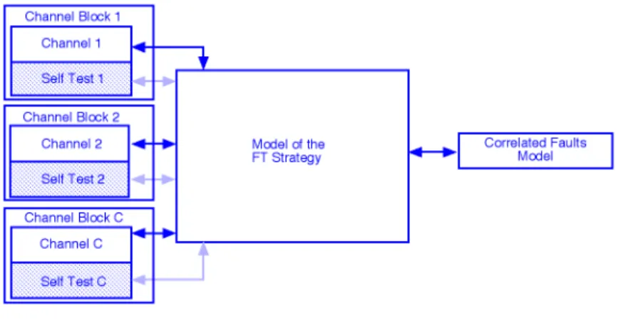
• the type of correlated faults (see Figure 3), that in turn, depends on the fault tolerance strategy. Three main modeling blocks have been distinguished (Figure 7). The first block model is used to represent the architecture of each channel, including lanes and self-tests for diagnosis. The second block model represents the fault tolerance strategy. The third one models the effects of correlated faults.
Figure 7 — The main block models
Each channel block is divided into two parts:
• the top part which models the occurrence of independent hardware and software errors within the channel;
• the bottom part which models the self-test diagnosis that determines whether the fault is permanent or temporary.
Erreur ! Source du renvoi introuvable. gives the number of places, transitions and states of the
models of the three instances. The significant number of states obtained for the Markov chain describing the space instance results from the larger number of timed transitions in the GSPN that are: i) induced by the high number of successive faults that can be tolerated by the instance, and ii) needed to model the recovery strategy implemented by the two diversified lanes.
Table 2 — Complexity of the models
Railway Nuclear Space
Generalized stochastic Petri nets # Places 88 65 84 # Transitions (timed) 178 (51)* 153 (40)* 699 (260)* Markov chains # States 352 150 21944
* Values in parenthesis give the number of timed transitions in the GSPN
A verification of the structural properties (such as liveness, boundedness, etc.) of the GSPNs was carried out independently for each of the block models. Furthermore, extensive sensitivity analyses were performed to validate the global model obtained for each instance; selected results of these analyses are presented in section 6.2. These verification and validation tasks were supported by the SURF-2 tool [19].