UNIVERSITÉ DE MONTRÉAL
Simultaneous Manganese Removal and Remineralization Of Soft
Waters Via Calcite Contactor
HAMED POURAHMAD
DÉPARTEMENT DES GÉNIES CIVIL, GÉOLOGIQUE ET DES MINES (CGM) ÉCOLE POLYTECHNIQUE DE MONTRÉAL
MÉMOIRE PRÉSENTÉ EN VUE DE L’OBTENTION DU DIPLÔME DE MAÎTRISE ÈS SCIENCES APPLIQUÉES
(GÉNIE CIVIL) DÉCEMBRE 2018
UNIVERSITÉ DE MONTRÉAL
ÉCOLE POLYTECHNIQUE DE MONTRÉAL
Ce mémoire intitulé :
Simultaneous Manganese Removal and Remineralization Of Soft
Waters Via Calcite Contactor
Présenté par : POURAHMAD, Hamed
En vue de l’obtention du diplôme de : Maîtrise ès sciences appliquées
A été dûment accepté par le jury d’examen constitué de : M. COMEAU, Yves, Ph. D., président
M. BARBEAU, Benoit, Ph. D., membre et directeur de recherche Mme. VANEECKHAUTE, Céline, Ph.D., membre
DEDICATION
ACKNOWLEDGEMENTS
I would like to express my sincere gratitude to my research director Professor Benoit Barbeau, for his continues support and guidance throughout my master’s study. His patience and immense knowledge helped me in all the time. The door to Prof. Barbeau’s office was always open whenever I ran into a trouble spot or had a question about my research or writing. I would like to thank you for all the priceless advices and for giving me the great opportunity of being a part of your team. I acknowledge the members of my committee, Professor Yves Comeau and Professor Céline Vaneeckhaute for taking interest in my work and examining my thesis.
My special thanks to my mentor Maryam Haddad. I learned so much from you in each step of this project. I deeply appreciate your presence from the very beginning of the project.
My sincere gratitude goes to Dominique Claveau-Mallet for helping me in doing the modeling part of this work and offering her time and valuable technical advices. I truly appreciate her professionalism.
I also gratefully acknowledge the financial support by the Canadian NSERC Discovery Grant Program which made this research work possible.
My deepest appreciation goes to the technicians and research associates in the Department of Civil, Geological and Mining Engineering, particularly Mireille, Gabriel, Yves, Julie and Jacinthe for their excellent assistance. In addition, I thank the secretary of the Department of Civil, Geological and Mining Engineering for helping us and providing us with an ideal atmosphere.
Special thanks to my Polytechnique friends, Sanaz, Saber and Nargess. I am very grateful to all my colleagues in our research group and my fellow labmates and officemates for their cooperative manner and friendly support.
Finally, I would like to express my ineffable gratitude to my mother, lovely brothers and sisters, and in-laws for their solid support and undoubtedly, I would not have finished my thesis without their support.
RÉSUMÉ
Les eaux souterraines représentent 96% de l’approvisionnement en eau douce non gelée et fournissent près de la moitié de l’approvisionnement en eau potable dans le monde. En Amérique du Nord, environ 28% des Canadiens et 44% de la population américaine, vivant principalement en zone rurale, dépendent des eaux souterraines pour leur principale source d'approvisionnement en eau. Des concentrations élevées de manganèse (Mn) existent souvent naturellement dans les eaux souterraines (Civardi & Tompeck, 2015). Bien que la présence de manganèse dans l’eau potable pose des problèmes d’ordre esthétique et opérationnel, (Bouchard et al., 2011) ont indiqué que la consommation d’eau très concentrée en manganèse entraînait une déficience intellectuelle et des désordres neurologiques chez les enfants d’âge scolaire. Par conséquent, Santé Canada (2016) a récemment proposé une limite fondée sur la santé pour protéger les enfants des effets neurotoxiques. La filtration catalytique ou l'échange ionique cationique couplée aux procédés d'osmose inverse au point d'utilisation sont largement utilisés pour éliminer le manganèse et le fer des eaux souterraines. Cependant, le risque de lessivage du manganèse par des filtres catalytiques mal opérés, une consommation élevée de sel pour la régénération par échange d'ions et une quantité considérable de déchets de saumure, polluante pour l'environnement, sont des inconvénients courants de ces méthodes. En guise d'alternative, l'application du procédé de membrane de nanofiltration à fibres creuses (HFNF) a récemment été proposée pour traiter les sources d'approvisionnement en eau souterraine domestiques dans les petites communautés/régions isolées ou même pour des applications domestiques pour lesquelles les ressources financières et techniques disponibles sont une préoccupation importante lors du choix des solutions. Même si l’application d’un procédé membranaire peut constituer une solution attrayante pour une élimination efficace du manganèse, du fer et des agents pathogènes, la propriété non sélective des membranes de nanofiltration (NF) peut entraîner l’appauvrissement des niveaux de dureté et d’alcalinité des eaux souterraines et, par la suite, une eau traitée corrosive. Par conséquent, le procédé à membrane de nanofiltration doit être associé à une étape de polissage, tel qu'un contacteur de calcite (CaCO3),
pour ajuster le niveau de dureté de son perméat. En outre, un autre avantage intéressant de la calcite réside dans sa capacité à adsorber des cations métalliques divalents à sa surface (Aziz & Smith, 1996; Franklin & Morse, 1983). Ainsi, développer un procédé capable d'éliminer efficacement les résidus de manganèse du procédé de nanofiltration (qui n'est pas nécessairement totalement rejeté à cette étape) tout en ajoutant de la dureté à l'eau traitée est d'un grand intérêt.
L’objectif principal de ce projet de recherche est de concevoir une étape de polissage simple, mais robuste, capable d’ajuster le niveau de dureté (minimum cible de 40 mg CaCO3 L-1) et d’éliminer
les traces de manganèse de l’eau douce (limite cible de 0,02 mg Mn L-1). De manière plus détaillée,
les objectifs spécifiques suivants sont définis: (1) déterminer le rôle des spécifications du support (utilisation de calcite pure ou d’un mélange de calcite et de CorosexTM (MgO)), (2) sélectionner les
meilleures conditions pour un fonctionnement efficace d’un contacteur de calcite comme étape de polissage (e.g. température, EBCT), (3) étudier la signification et le devenir du manganèse sorbé sur les performances globales d’un contacteur de calcite en fonctionnement à long terme et (4)
modéliser le comportement à long terme d’un contacteur de calcite utilisé pour la reminéralisation de l'eau potable.
Dans la première phase de ce projet, la performance globale d’un contacteur de calcite pour l’élimination du manganèse et la reminéralisation de l’eau douce en utilisant deux concentrations initiales de manganèse (e.g. 0,5 et 5 mg Mn L-1) a été étudiée. Le contacteur de calcite a démontré une efficacité élevée d’élimination du manganèse (moins de 20 µg Mn / L dans l’effluent); toutefois, la libération de dureté a diminué de 32 à 20 mg de CaCO3 L-1 après 600 h de
fonctionnement dans des conditions de concentration élevée en manganèse. Sur la base des résultats, dans la deuxième phase, l’impact négatif de la couche de manganèse nouvellement formée sur la vitesse de dissolution de la calcite à l’aide d’expériences continues de désorption-dissolution dans des colonnes plus petites a été étudié. Pour une concentration élevée de manganèse (e.g. 5,0 mg Mn L-1) dans l'eau d'alimentation, la couche formée était principalement composée de
manganèse, qui inhibe le transfert de masse du noyau de calcite à la phase liquide. La couche superficielle a été identifiée à 5,2% d'oxydes de manganèse (MnOx) par spectroscopie
photoélectronique à rayons X (XPS). Par conséquent, il est postulé que l'élimination du Mn commence par une réaction de sorption d'échange d'ions entre le manganèse soluble de la phase aqueuse et le calcium de la matrice de calcite, suivie d'une recristallisation lente du carbonate de manganèse en oxyde de manganèse. D'autre part, lorsque la teneur en manganèse dans l'eau d'alimentation était inférieure (e.g. 0,5 mg Mn L-1), une quantité considérablement inférieure de
MnOx était détectée sur la calcite. Pour toutes les conditions examinées, la formation de ce revêtement améliorait l'élimination du manganèse en raison de la nature autocatalytique de l'adsorption/oxydation du manganèse dissous par MnOx. Quant à la troisième phase, l'efficacité à long terme d'un contacteur de calcite a été modélisée à l'aide d'un modèle mécaniste basé sur la dissolution de la calcite et la formation progressive d'une couche d'oxyde de manganèse, implémenté dans le logiciel PHREEQC à l'aide d'une interface MATLAB via des modules IPHREEQC afin de prédire la réduction dans la libération de dureté attendue en fonctionnement à long terme. Le modèle a été calibré avec des données expérimentales et a abouti à des courbes de percée réalistes. Afin de prédire avec précision le pH du flux d'effluent, une recristallisation à vitesse lente de MnCO3 en MnO2 a été posée (par rapport à une précipitation rapide de MnO2 ou à
l'absence de formation de MnO2). Enfin, étant donné qu'après un fonctionnement prolongé du
contacteur de calcite en présence de concentrations élevées de manganèse, l'objectif de reminéralisation n'a pas été pleinement atteint, une solution possible a été testée en utilisant un mélange de calcite et de CorosexTM (MgO) comme moyen de filtration. À cette fin, un premier
rapport optimal de 80% / 20% pour Calcite / CorosexTM a été obtenu, puis la colonne a été exploitée
avec une concentration de manganèse élevée (5 mg Mn L-1) avec le rapport choisi pour étudier
l'efficacité du contacteur en reminéralisation d’eau douce avec élimination simultanée du manganèse. La colonne a démontré une efficacité élevée: dans le fonctionnement à long terme, le contacteur a pu éliminer plus de 99% du manganèse dissous de l'eau d'alimentation synthétique et a ajouté plus de 40 mg de CaCO3 L-1 de dureté à l'alimentation douce. La condition stable a été
fonctionnement par rapport à plus de 200 h de fonctionnement). L’accumulation de résidus de Mn nouvellement formés a augmenté la perte de charge et entraîné l’encrassement du filtre. Il est important de noter que l’utilisation d’un mélange de calcite et de Corosex ne semble pas une option prometteuse pour une opération à long terme si la concentration de manganèse dans l'alimentation est trop élevée (e.g. 5 mg Mn L-1). Cependant, pour des concentrations de Mn plus réalistes (e.g.
0,2 mg Mn L-1 et moins), l’ajout d’une petite portion de Corosex au filtre contribuerait à améliorer
ABSTRACT
Groundwater (GW) accounts for 96% of all unfrozen fresh water supply and provides nearly half of the world’s drinking water supply. In North America, approximately 28% of Canadians and 44% of the United States population, mainly living in rural areas, rely on GW as their main water supply. High manganese (Mn) concentrations often naturally exist in GW (Civardi & Tompeck, 2015). Despite the fact that the presence of Mn in finished water causes aesthetic and operational issues, (Bouchard et al., 2011) reported that consumption of water with high Mn concentration led to significant intellectual impairment and neurological disorders in school-age children. Consequently, Health Canada (2016) has recently proposed a health-based limit to protect children from neurotoxic effects. Catalytic filtration or cationic ion exchange (IX) coupled with point-of-use reverse osmosis processes are widely implemented to remove Mn and Fe from GW. However, the risk of Mn leaching from improperly operated catalytic filters, high salt consumption for IX regeneration and a considerable amount of brine waste production, which pollutes the environment, are common drawbacks of these methods. As an alternative, the application of hollow fiber nanofiltration (HFNF) membrane process has been recently proposed for treating domestic GW supplies in small/remote communities or even for domestic applications where the financial and technical resources are important concerns. Even though the application of a membrane process can be an appealing solution for effective removal of Mn, Fe and pathogens, non-selective property of the HFNF membranes may result in depletion of GW hardness and alkalinity levels and subsequently, corrosive treated water. Therefore, the HFNF process should be coupled with a polishing step, such as calcite contactor, to adjust the hardness level of its soft permeate. Moreover, another interesting advantage of calcite lies in its ability to sorb divalent metallic cations (Me2+) on
its surface (Aziz & Smith, 1996; Franklin & Morse, 1983). Thus, developing a process which can efficiently remove the leftover of Mn from the NF process (which is not necessarily fully rejected in this step) while adding hardness to treated water is of great interest.
The main objective of this research project is to design a simple, yet robust polishing step which can adjust the hardness level (target minimum of 40 mg CaCO3/L) and remove the traces of Mn
from the soft water (target limit of 0.02 mg Mn/L). On a more detailed basis, the following specific objectives are defined: (1) determine the role of the media specifications (i.e., use of pure calcite (CaCO3) or a blend of calcite and CorosexTM (MgO)), (2) screen the best operational conditions for
the efficient operation of a calcite contactor as a polishing step (i.e., temperature, EBCT), (3) investigate the significance and fate of sorbed Mn on the overall performance of a calcite contactor in long-term operation and (4) model the long-term behavior of a calcite contactor operated for drinking water remineralization.
In the first phase of this project, the overall performance of a calcite contactor for the removal of Mn and remineralization of soft water using two initial concentrations of Mn (i.e. 0.5 and 5 mg Mn L-1) was investigated. The calcite contactor demonstrated high Mn removal efficiency (below 20
µg Mn/L in the effluent); however, the hardness release decreased from 32 to 20 mg CaCO3 L-1
phase, the negative impact of newly-formed Mn-layer on calcite dissolution rate using continuous desorption-dissolution experiments in smaller columns was investigated. For an elevated Mn concentration (i.e. 5.0 mg Mn L-1) in the feed water, the coated layer was mainly composed of Mn
which inhibits the mass transfer from the calcite core to the liquid phase. The superficial layer was identified as 5.2% Mn oxides (MnOx) by X-ray photoelectron spectroscopy (XPS). Therefore, it is postulated that Mn removal starts with an ion exchange sorption reaction between soluble Mn2+
from aqueous phase and Ca2+ from the CaCO
3 matrix which is followed by a slow recrystallization
of MnCO3 into MnO2. On the other hand, when the Mn content in the feed water was lower (i.e.
0.5 mg Mn L-1), a considerably lower amount of MnOx was detected on the coated media. For all
the examined conditions, the formation of this coating improved Mn removal due to the autocatalytic nature of adsorption/oxidation of dissolved manganese by MnOx. As for the third phase, the long-term efficiency of a calcite contactor was modeled using a mechanistic model based on calcite dissolution and progressive formation of a MnO2 layer which was implemented in
PHREEQC software using a MATLAB interface via IPHREEQC modules to predict the reduction in hardness release expected in long-term operation. The model was calibrated with experimental data and resulted in realistic breakthrough curves. In order to accurately predict the pH of the effluent stream, a slow-rate recrystallization of MnCO3 into MnO2 was implemented (compared to
fast precipitation of MnO2 or absence of MnO2 formation). Finally, given that after long-term
operation of the calcite contactor in elevated Mn concentrations, the remineralization objective was not fully met, a possible solution was tested using a blend of calcite and CorosexTM (MgO) as the
filtration media. For this purpose, first optimum ratio of 80% / 20% for Calcite/ CorosexTM was
obtained, then the column was operated under elevated Mn concentration (5 mg L-1 Mn2+) with the
chosen ratio to investigate the efficiency of the contactor in remineralization of soft water with simultaneous Mn removal. The column demonstrated high efficiency: in the long-term operation, the contactor was able to remove over 99% of dissolved Mn from the synthetic feed water (SFW) and added above 40 mg CaCO3/L of hardness to the soft feed. The stable condition was reached
much sooner than the previous phase when only calcite was used (10 h of operation versus above 100 h of operation). Accumulation of newly formed Mn residue increased the head loss overtime and caused filter clogging. It is important to note that using a blend of calcite and CorosexTM does
not seem like a promising option for long-term operation if the Mn concentration in the feed is unrealistically high (i.e. 5 mg L-1 Mn2+). However, for more realistic Mn concentrations (i.e. 0.2
mg/L and less), adding a small portion of MgO to the filter would help to improve the hardness addition.
TABLE OF CONTENTS
DEDICATION... III ACKNOWLEDGEMENTS ... IV RÉSUMÉ ... V ABSTRACT ... VIII TABLE OF CONTENTS ... X LIST OF TABLES ... XIII LIST OF FIGURES ... XIV LIST OF SYMBOLS AND ABBREVIATIONS ... XVI LIST OF APPENDICES ... XVIIIINTRODUCTION ... 1
1.1 Background ... 1
1.2 Structure of the thesis... 2
LITERATURE REVIEW ... 3
2.1 Remineralization ... 3
2.1.1 Remineralization options ... 3
2.1.2 Calcite contactor process for remineralization ... 4
2.1.3 Theory of Calcite dissolution ... 5
2.1.4 The reaction rate of calcite dissolution ... 6
2.1.5 Calcite dissolution models ... 7
2.1.6 Parameters affecting the calcite dissolution rate (contactor design) ... 8
2.1.7 Calcite media characteristics ... 9
2.1.8 Empty Bed Contact Time (EBCT) ... 12
2.2 Manganese removal ... 15
2.2.1 Manganese removal options ... 15
2.2.2 Sorption of manganese on calcite surface ... 16
2.2.3 Models describing Mn sorption on calcite surface ... 18
2.3 Knowledge gap based on the literature review ... 18
RESEARCH OBJECTIVES, HYPOTHESES AND METHODOLOGY ... 19
3.1 Objectives and hypotheses ... 19
3.1.1 General objective ... 19
3.1.2 Specific objectives ... 19
3.1.3 Research hypotheses ... 19
3.2 Methodology ... 20
3.2.1 Continuous sorption-dissolution experiments with calcite media ... 20
3.2.2 Impact of Mn coating on calcite dissolution ... 23
3.2.3 Model description and numerical simulations ... 24
3.2.4 Sorption-dissolution experiments with a blend of calcite and CorosexTM media .. 26
ARTICLE 1 - IMPACT OF MEDIA COATING ON SIMULTANEOUS MANGANESE REMOVAL AND REMINERALIZATION OF SOFT WATER VIA CALCITE CONTACTOR ... 29
4.1 Introduction ... 30
4.2 Materials and methods ... 32
4.2.1 Calcite media and synthetic feed water ... 32
4.2.2 Experimental design ... 33
4.2.3 Continuous sorption-dissolution experiments ... 33
4.2.4 Characterisation of calcite Mn-loaded media ... 34
4.2.6 Batch sorption experiments on Mn-loaded media ... 35
4.2.7 Model description and numerical simulations ... 35
4.3 Results and discussion ... 37
4.3.1 Media characterization ... 37
4.3.2 Effect of initial Mn concentration on long-term operation of a calcite contactor . 39 4.3.3 Effect of Mn loading on calcite dissolution ... 40
4.3.4 Mn removal kinetics ... 41
4.3.5 Prediction of long-term operation of calcite contactor by simulations ... 42
4.4 Conclusion ... 45
SUPPLEMENTARY RESULTS ... 47
5.1 Impact of EBCT on Mn removal and hardness release ... 47
5.2 Impact of temperature on Mn removal and hardness release ... 48
5.3 Impact of mixed beds (calcite/MgO) on Mn removal and hardness release ... 49
5.3.1 Identification of Calcite/ CorosexTM ratio to maximise hardness release ... 49
5.3.2 Sorption-dissolution experiments with a blend of calcite and CorosexTM ... 50
5.4 Conclusion ... 53
GENERAL DISCUSSION ... 54
6.1 Calcite contactor process for Mn removal and hardness adjustment ... 54
6.2 Mn Coating effect on calcite dissolution ... 55
6.3 Modeling the long-term performance of a calcite contactor for Mn removal and remineralization via PHREEQC ... 56
6.4 Blend of Calcite/ CorosexTM media application ... 56
CONCLUSIONS AND RECOMMENDATIONS ... 58
BIBLIOGRAPHY ... 60
LIST OF TABLES
Table 2-1: Major features of the calcite dissolution models ... 7
Table 2-2: Shape factor for different shapes and their ratio compared to the standard spherical shape (volumes are kept the same)... 10
Table 2-3: Design superficial velocities and particle size used for calcite contactors in different case studies (Walker, 2012). ... 13
Table 3-1: Calcite media characteristics... 21
Table 3-2: Mn loading in the different mini-columns ... 23
Table 3-3: Applied equations for calcite dissolution and manganese removal modeling ... 25
Table 3-4: Magnesium oxide (CorosexTM) media characteristics ... 26
Table 4-1: Calcite media characteristics... 33
Table 4-2: Mn loading in the different mini-columns ... 35
Table 4-3: Applied equations for calcite dissolution and manganese removal modeling ... 36
Table 4-4: SEM images and EDX analyses of calcite media drawn from different Mn loadings on the calcite media. ... 37
Table 4-5: High resolution XPS spectra for Mn loaded calcite ... 39
LIST OF FIGURES
Figure 2-1: Schematic of a calcite contactor ... 5
Figure 2-2: Example of a relationship between particle diameter and height of the limestone bed (Hernández-Suárez, 2005). ... 10
Figure 2-3: Specific conductivity of the finished water VS. contact time achieved with different calcite samples (L1 to L5) (Ruggieri et al., 2008)... 12
Figure 2-4: Average [Ca2+] in the calcite reactor as a function of retention time for the six case studies: 10, 20, and 30 m/h flow rates (□, Δ, and X, respectively) and gray and black signs for the 2 different acid dosages of 490 and 721 mg H2SO4/L (Lehmann et al., 2013). ... 13
Figure 2-5-Relationship between superficial velocity (m/h) and turbidity ... 14
Figure 2-6: potential (E h in V) as a function of the pH showing the stability zones of manganese-containing compounds in aqueous solution. Source: adopted from Stumm and Morgan (1970) ... 17
Figure 3-1: The size distribution curve for grain size ranging between 0.2-0.7 ... 21
Figure 3-2: Schematic illustration of continuous sorption-dissolution set-up ... 22
Figure 3-3: Schematic of mini-columns set-up ... 24
Figure 3-4: The size distribution curve of CorosexTM for grain size ranging between 0.8-1.6 ... 27
Figure 3-5: Filter bed material: Calcite (left) and CorosexTM (right) ... 28
Figure 4-1: Schematic illustration of the continuous sorption-dissolution set-up ... 34
Figure 4-2: Concentrations of a) Mn2+ and b) hardness measured over 800 h at the effluents (EBCT=10 min) of calcite contactors fed either with SFW containing 0.5 or 5 mg Mn2+ L-1 ... 40
Figure 4-3: Hardness increase achieved by mini-columns containing increased Mn loading on the calcite media (the numbers in parenthesis represent the amount of the Mn loading of media (mg Mn g-1calcite). EBCT = 10 min and the feedwater had no hardness, pH = 6.0 and T = 23 °C. ... 41
Figure 4-4: Impact of Mn preloading on Mn+2 removal by calcite in a mixed batch reactor for a)
fresh calcite, b) Mn preloaded calcite (i.e.15 mg Mn g-1 calcite) ... 42
Figure 4-5: Calibrated model predictions for the hardness and manganese data for an EBCT=10 m of the calcite contactor over 700 h of operation. Feed = 5.0 mg Mn L-1. The experimental data
are shown by symbols while model predictions are provided as solid lines. ... 43 Figure 4-6: Effect of MnO2 recrystallization rate (M/s, indicated in legend) on pH of the effluent,
assuming an influent with a Mn concentration of (a) 5.0 mg Mn2+ L-1 or (b) 0.5 mg Mn2+ L-1.
... 44 Figure 5-1: EBCT effect on Mn2+ removal in a calcite contactor with SFW containing a) 0.5 mg
Mn L-1 (column A) and b) 5 mg Mn L-1 (column B)... 48
Figure 5-2: EBCT effect on hardness adjustment profile of a calcite contactor with SFW containing a) 0.5 mg Mn L-1 (column A) and b) 5 mg Mn L-1 (column B) ... 48
Figure 5-3: Temperature effect on Mn removal efficiency in a calcite contactor with SFW containing a) 0.5 mg Mn L-1 (column A) and b) 5 mg Mn L-1 (column B) ... 49
Figure 5-4: Temperature effect on efficiency of a calcite contactor in remineralization of soft SFW containing a) 0.5 mg Mn L-1 (column A) and b) 5 mg Mn L-1 (column B) ... 49
Figure 5-5: Hardness addition profile for four ratios of Calcite/ CorosexTM, Feed had no Mn and no
LIST OF SYMBOLS AND ABBREVIATIONS
AFM Atomic Force MicroscopyBE Binding Energy
BET Brunauer–Emmett–Teller
Ca Calcium
CCM Constant Capacitance Model DLM Diffuse Layer Model
EBCT Empty Bed Contact Time
EDTA Ethylenediaminetetraacetic Acid EDX Energy Dispersive X-ray
FEG-SEM Field Emission Gun Electron Microscope
GW Groundwater
HFNF Hollow Fiber Nanofiltration ICP Inductively Coupled Plasma
ICP-AES Inductively Coupled Plasma - Atomic Emission Spectroscopy ICP-OES Inductively Coupled Plasma - Optical Emission Spectrometry
IX Ion Exchange
LSI Langelier Saturation Index MGD Million Gallons Per Day
Mn Manganese
POE Point of Entry
PWP Plummer, Parkhurst, Wigley SCM Surface Complexation Model SEM Scanning Electron Microscope
SFW Synthetic Feed Water
SMCL Secondary Maximum Contaminant Level SPM Surface Precipitation Model
TLM Triple Layer Model
USEPA United States Environmental Protection Agency XPS X-Ray Photoelectron Spectroscopy
LIST OF APPENDICES
INTRODUCTION
1.1 Background
Groundwater (GW) accounts for 96% of all unfrozen fresh water supply and provides nearly half of the world's drinking water supply. In North America, approximately 27% of Canadians and 44% of the United States population, mainly living in rural areas, rely on GW as their primary water supply. High manganese (Mn) concentrations often naturally exist in GW (Civardi & Tompeck, 2015). Apart from the fact that the presence of Mn in finished water causes aesthetic and operational issues, manganese is also under review in Canada and the US for a possible health-based regulation given the increased evidence of the neurotoxicity of manganese, especially for children (Bouchard et al., 2011; Dion et al., 2018). Thus, efficient removal of Mn from drinking water is an emerging concern. Catalytic filtration or cationic ion exchange (IX) coupled with point-of-use reverse osmosis are the processes most widely implemented to remove Mn and Fe from GW in domestic applications. However, the risk of Mn leaching from improperly operated point-of-entry catalytic filters, high salt consumption for IX regeneration and a considerable amount of brine waste production, which pollutes the environment, are common drawbacks of these treatment options. As an alternative, recently, Haddad et al. (2018) proposed the application of a hollow fiber nanofiltration (HFNF) membrane process for treating domestic GW supplies in small/remote communities or even for domestic applications where the financial and technical resources are important concerns. Even though the application of HFNF process can be an appealing solution for effective removal of Mn, Fe and pathogens, the non-selective property of the HFNF membranes may result in the almost complete depletion of GW hardness and alkalinity levels which would subsequently lead to the distribution of corrosive treated water. Therefore, the HFNF process should be coupled with a remineralization step (Haddad et al., 2018). To achieve this goal, filtration through a bed made of a blend of calcite (i.e., calcium carbonate), often mixed with magnesium oxide, is used as a remineralization strategy for domestic purposes and small water systems. This treatment option is most often referred to as calcite or limestone contactor. Remineralization of finished water from desalination plants is another common application of this process. Calcite dissolution adds calcium hardness and bicarbonate alkalinity which are two essential drinking water elements required to minimize water corrosivity. In this regard, several pieces of research have shown that calcite filtration is a reliable remineralization method as no continuous chemical addition is required and limestone is inexpensive, readily available, safe and easy to store and manipulate (Shemer et al., 2013; Van Der Laan. H., 2016).
Moreover, another interesting advantage of calcite lies in its ability to sorb divalent metallic cations (Me2+) on its surface (Aziz & Smith, 1996; Franklin & Morse, 1983). Due to its high removal
efficiency, a number of researchers recommended using calcite media for manganese removal from acid mine drainage (Aziz & Smith, 1992, 1996; Thornton, 1995; Zachara et al., 1991). As mentioned earlier, in drinking water applications, manganese removal is a common treatment
objective because of the fact that manganese naturally occurs in surface and groundwater supplies due to weathering and leaching of metal-bearing minerals, rocks and soils rich in organic matter, thermal stratification in lakes and contamination by industrial effluents (Kenari, 2017). It is anticipated that limestone contactor can be used to simultaneously remineralize soft waters as well as remove manganese. In this regard, the present investigation is a complement to the previous work of (Haddad et al. 2018) on designing a simple, yet robust system to efficiently treat domestic GW supplies.
1.2 Structure of the thesis
This thesis is divided into seven chapters. Chapter 1 presents a general background on corrosion control and Manganese removal. Chapter 2 presents a comprehensive literature review of the application of calcite contactors for remineralization and manganese removal in water treatment sector. The research objectives, hypotheses and methodology to carry out the specific objectives are presented in chapter 3. Chapter 4 presents results of this research in the form of a submitted manuscript to Water Research Journal followed by chapter 5 which mainly presents the supplementary results. The article intends to determine the effect of Mn-coating on calcite dissolution rate and eventually modeling the long-term behavior of a calcite contactor operated for drinking water remineralization. Finally, a general discussion is provided in chapter 6 followed by conclusions and recommendations.
LITERATURE REVIEW
The literature review chapter is divided into two sections. The first section addresses the issue of remineralization via calcite contactor, and the second section discusses the literature assessing the performance of limestone contactor for Mn removal.
2.1 Remineralization
Remineralization process is considered for situations where it is needed to increase the mineral content of soft or demineralized water. Some surface waters are naturally soft, but the major source of demineralized water is the product of desalination plants. Purified bottled water is another area where increasing the mineral content of water is sought in order to improve the taste of water. Demineralized water is devoid of essential minerals, i.e., calcium and magnesium. This lack of minerals raises some problems such as corrosion in the pipelines, health impacts as well as poor organoleptic characteristics. Since soft water is highly reactive with metals, it can cause severe corrosion difficulties when it is transported through conventional pipelines (Shemer et al., 2012). On the other hand, it is also desirable to remineralize waters to meet health requirements because calcium and magnesium are necessary for normal metabolism in the body. The lack of these ions in demineralized water gives rise to health impacts of drinking soft water, including sudden cardiac death (Kozisek, 2004). However, there is currently no minimal hardness concentration required in Canadian tap waters. Nevertheless, untreated soft waters should not be used directly as a drinking water and a certain degree of remineralization is crucial to increase the buffering capacity and pH, also to mitigate corrosion by-products, such as copper, and reduce corrosion in the distribution system and more importantly to re-introduce some essential ions from a health perspective (Shemer et al., 2013; Shemer et al., 2012).
2.1.1 Remineralization options
There are several options for remineralization but the primary objective of a remineralization process is to increase the Langelier Saturation Index (LSI) and increase the bicarbonate alkalinity and pH value of the targeted water (Withers, 2005). In the water industry, remineralization is generally achieved by the following three methods (Withers, 2005):
• Chemical solutions dosing (based on calcium chloride and sodium bicarbonate) • Carbon dioxide addition followed by lime dosing; or
• Carbon dioxide addition followed by calcite contactor.
Lime and caustic soda dosing can also be employed to readjust the pH. However, they typically provide only a small increase in alkalinity and hardness. As both chemicals are strong bases, low dosages are needed to increase pH to a target value typically ranging from 7.5 to 8.3. For such small dosages, the increase in mineral content is moderate to low. Nevertheless, these two options
are extremely common given that they are cost-effective in larger municipal systems. Various corrosion inhibitors are also used in the municipal water treatment sector (Withers, 2005). However, all the techniques mentioned above are implemented at municipal scale, for domestic purposes and small water systems, filtration through a bed made of a blend of calcite (i.e., calcium carbonate), often mixed with magnesium oxide (MgO), is often used as a remineralization strategy, which is referred to as calcite or limestone contactor. The main reason for adding MgO to the calcite media is due to the documented health benefits of Mg intake on cardiac health ((WHO), 2011). Remineralization of finished water from desalination plants is another common application of this process. As the primary goal of this study is to design a simple, yet robust system for efficient treatment of domestic GW supplies, calcite contactor is the best option for such a purpose as no continuous chemical addition is needed and limestone, as mentioned earlier, is inexpensive, readily available, safe and easy to store and manipulate (Shemer et al., 2013; Van Der Laan. H., 2016). 2.1.2 Calcite contactor process for remineralization
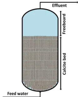
Calcite contactor is a filtration technique in which water passes through a bed of calcite grains while dissolving carbonate minerals from the grains into the passing water until the pH approaches equilibrium with calcium carbonate. Alkalinity, calcium, pH, and dissolved inorganic carbon concentrations increase with calcite dissolution (Yamauchi et al., 1987). The main components of a calcite bed include a contact tank which is filled with calcite grains, influent and effluent line, overflow line and access lid (mainly for media refill). Figure 2-1 is a schematic illustration of a typical calcite contactor. Equilibrium conditions depend on the contact time and initial water characteristics (pH, CO2 content, calcium, alkalinity and temperature) (Yamauchi et al., 1987). The calcium concentration of the feed water approaches that of the equilibrium but cannot exceed it (approx. 45-50 mg CaCO3/L). Calcite grains should be periodically added to the bed to replace
Figure 2-1: Schematic of a calcite contactor 2.1.3 Theory of Calcite dissolution
When water flows through a fixed bed of calcite grains, calcite dissolves which causes an enrichment in calcium ions and carbonate alkalinity. The parallel chemical reactions illustrating calcium carbonate equilibrium at 10 oC that is taking place in the solid/water interface are described
below through Eqs. 2.1 to 2.5 (Lehmann et al., 2013).
CaCO3 ⟷ Ca2+ + CO32- Ks = [#$%&]
∗
[#)*%+] = 4.4*10-9 pks = -8.36 2-1 CO2 + H2O ⟷ HCO3-+ H+ K1 = [,-./0]∗[, /.1] [-.2] = 3.44*10-7 pk1 = -6.46 2-2 HCO3- + H2O⟷ CO32- + H3O+ K2= 3-./ 204∗[, /.1] [,-./0] = 3.25*10-11 pk2 = -10.49 2-3CaCO3 + CO2 + H2O⟷ Ca2+ + 2HCO3- Ka= [-5
21]∗[,-. /0]2 [-.2] = 4.6*10-5 pka = -4.33 2-4 [Ca2+ ] = 1 28 [HCO3-]2-5 Where:
K1, 2, a = reaction constant at 10oC (mole/m2/s)
Ks = solubility product of calcite
[] = stoichiometric molar concentration (mol/l). 2.1.4 The reaction rate of calcite dissolution
The reaction rate is the speed at which a reaction occurs. In the dissolution of solids in water, the reaction rate can be calculated by either dissolution kinetics or mass balance. A general dissolution kinetic can be expressed using Eq. 2-6 which can be simply written for calcite grains:
9:
9;
= = ∗ >
2-6Where:
dt = contact time (s)
k = rate constant of calcite dissolution (mole/m2/s)
A = surface area of calcite grains (m2)
On the other hand, based on the principle of mass conservation, the mass change in the solid should be equal to that of the liquid phase (Fogler, 1999):
dM = dC ∗ V 2-7 Where:
dM = mass change (mol)
dC = concentration change (mole/m3)
V = volume of the reactor (m3)
Finally, calcite dissolution rate can be written as follows:
9-9;
= = ∗
DE 2-8
As it is seen from the above equation, DE (surface to volume ratio) plays an important role in the calcite dissolution rate. This ratio can be calculated for different shapes by the following equation:
D E
=
F∗(H+e)
9∗j 2-9
Where:
d = diameter of the grain (m)
j = shape factor
j
=
JKLMNON P JQOONRSTUO P 2-102.1.5 Calcite dissolution models
The three most common calcite dissolution models are the ones of Plummer, Parkhurst, Wigley (PWP) (1978), Yamauchi (1987) and Letterman (1987) (Letterman et al., 1987; Plummer et al., 1979; Plummer et al., 1978; Yamauchi et al., 1987). In the PWP and Yamauchi models, it is assumed that the flow is turbulent and the process is very fast; thereby, the calcite dissolution is controlled only by surface reactions, i.e., diffusional mass transport is neglected (Ghanbari, 2018; Plummer et al., 1979; Yamauchi et al., 1987). On the other hand, in the Letterman model, mass transfer is the key controlling mechanism used to predict calcite dissolution (Letterman et al., 1987).
Table 2-1: Major features of the calcite dissolution models
Model System description Assumptions
Plummer et al. (PWP) (Plummer
et al., 1979)
Dissolution of 0.3-0.6 mm calcite grains in a stirred system at temperatures of 5-60°C opened to atmospheric CO2 (in
contact with a constant pressure of CO2)
- Diffusional mass transfer is neglected - Concentration of aggressive CO2 is
used as the driving force
- Dissolution occurs by the three simultaneous chemical reactions: CaCO3 + H+ óCa2+ + HCO3- (I)
CaCO3 +H2CO3óCa2+ +2HCO3- (II)
CaCO3 +H2O ó Ca2+ + CO32- +H2Oó Ca2+ + HCO 3- +OH- (III) Yamauchi (Yamauchi et al., 1987) Dissolution of 1.4-10 mm calcite particles via a flow of CO2 acidified
distilled water at 40°C in a 100 mm diameter column with the following characteristics:
Packing length = 0.5-2.4 m [CO2]feed = 2.4-5 mM
- Diffusional mass transfer is neglected - The surface chemical reaction controls the dissolution reaction
- Concentration of aggressive CO2 is
Retention time = 55-270 s Closed to atmospheric CO2
- Calcite dissolution has no effect on the size of the calcite particles as they are replaced by fresh calcite frequently. - Ideal plug flow
Letterman (Letterman et al.,
1987)
Dissolution of 9.6-32 mm calcite particles by a flow of HCl-acidified soft water between 9°C and 22 °C in four 150-380 mm diameter columns with the following characteristics:
-Packing length = 2.1-3.5 m [CO2]feed
HCl acidity = 0.002-0.4 mM
-Retention time = 230-3800 s - Closed to atmospheric CO2
- Dissolution is assumed to be controlled by the use of three resistances in series:
(1) liquid film transfer; (2) surface reaction; and (3) residual layer mass transfer.
- The calcium difference is used as the driving force.
- The calcite dissolution has no effect on the size of the calcite particles as they are replaced by fresh calcite frequently.
- Non-ideal flow with dispersion effect
2.1.6 Parameters affecting the calcite dissolution rate (contactor design)
The rate of calcite dissolution and generally efficiency of a calcite contactor is highly dependent on various factors such as influent water composition, empty bed contact time (EBCT), media characteristics and superficial velocity (Shemer et al., 2013). In what follows, the effect of each parameter on the performance of a calcite contactor is discussed based on the relevant information from the literature.
2.1.6.1 Influent water characteristics 2.1.6.2 Impurities in the feed water
Past research has shown that calcite dissolution is adversely affected by the presence of substances like magnesium, organic matter and copper (Arvidson et al., 2006; Erga, 1956; Morse et al., 2007). (Arvidson et al., 2006), by surface observations using atomic force microscopy (AFM), have shown that calcite dissolution is decreased in the presence of dissolved magnesium. For the purpose of the present study, the impact of inhibitors will be neglected since the main focus of this research is remineralization of highly pure water derived from HFNF process, so investigating the adverse effects of inhibitors such as metallic impurities is beyond the scope of this research effort.
2.1.6.3 Saturation state of calcite
The driving force for calcite dissolution is its saturation state with respect to CaCO3 and dissolution occurs only in a condition that the water is undersaturated with CaCO3. The Langelier Saturation Index (LSI) is one of several tools used to estimate the degree of saturation of calcium carbonate in water (Ghanbari, 2018). The general formula to calculate the Langelier Saturation Index (LSI) is as follows (Benefield et al., 1982):
LSI = pH – pHs 2-11
Where:
pH = measured pH of the sample
pHs = calculated saturation pH of the same sample
And once it is calculated, one of the three following scenarios can happen (Benefield et al., 1982): • LSI>0 Water is undersaturated with respect to calcium carbonate and will not accept more
CaCO3.
• LSI=0 Water is neutral, so it is neither scale-forming nor scale removing.
• LSI<0 Water is undersaturated with respect to calcium carbonate and tends to dissolve more calcium carbonate.
2.1.7 Calcite media characteristics
(Ruggieri et al., 2008) conducted a research on limestone selection criteria and concluded that calcite dissolution rate could be enhanced or inhibited depending on available reaction surface area of grains and the impurities they contain. According to the general calcite dissolution rate formula (Eq. 2-8), the higher the specific surface area (A/V), the higher the calcite dissolution rate is, hence the lower the required EBCT to reach the equilibrium. Obviously, A/V ratio is affected by the size and/or sphericity of a grain. A number of researchers claimed that smaller calcite particles have a superior dissolution rate due to their larger specific surface area (Letterman et al., 1991; Shemer et al., 2013; Yamauchi et al., 1987). Based on a research carried out by (Hernández-Suárez, 2005), limestone bed height is influenced by the particle diameter, as shown in the Fig. 2-2. Finally, it is important to note that calcite size will progressively be reduced as the particle dissolves in water. Therefore, a calcite bed is expected to include media with variable particle size, a phenomenon which complexifies the modeling of calcite dissolution in packed bed reactor.
Based on a report published by Texas Water Treatment Board, the recommended height of the calcite contactor should be in the range of 1 to 3 meters (3 to 10 feet) (W. Walker, 2012).
Figure 2-2: Example of a relationship between particle diameter and height of the limestone bed (Hernández-Suárez, 2005).
More recently, S. Ghanbari (2018) tabulated shape factor for different geometries using Eq. 2-10, as shown in table 2-2. According to the table, a spherically shaped grain has a smaller surface area than the irregularly shaped ones (Ghanbari, 2018).
Table 2-2: Shape factor for different shapes and their ratio compared to the standard spherical shape (volumes are kept the same)
Form Unites V(mm3) a(mm) A(mm2) A/V(mm) Compare to spherical
(A/V/Ap/Vp) Spherical a 0,52 1,0 3,14 6 1,00 Rectangle a, b = a/3 h =2a 0,52 0,9 5,11 10 1.66 Square a 0,52 0,8 3,90 7 1.16
Tetrahedron a 0,52 1,6 4,68 9 1.5
Cylinder a, h = 2a 0,52 0,7 3,78 7 1.16
Cone a, a=h 0,52 1,3 5,17 10 1.66
As mentioned earlier, calcite dissolution rate is also dependent upon the chemical characteristics like the amount and type of impurities. Ruggieri et al. (2008) carried out a research on limestone selection criteria for water remineralization and they used five different calcite samples containing a different percentage of impurities (Ruggieri et al., 2008). Table 2-3 demonstrates a summary of the composition of the calcite samples used.
Table 2-3: Characterization of limestone samples (L1 to L5)
Sample L1 L2 L3 L4 L5 %CaCO3 purity 98.3 97.9 99.6 92.8 97.5 % MgO 0.20 0.35 0.36 3.26 0.55 % Al2O3 0.04 0.25 0.02 0.15 0.43 % Fe2O3 0.03 0.12 0.01 0.25 0.26 Particle size (µm) <5 <20 <5 >100 >100
BET surface area (m2/g)
0.43 0.66 0.11 0.26 0.82
Specific conductivity of the finished water was used as an indicator of limestone dissolution, as shown in Fig. 2-3. The authors observed textural differences between used calcite samples which can be reflected via physical properties of the samples (i.e., BET specific surface). Although samples had a different particle size, their cementing ability were different which resulted in different BET specific surface. Hence a solid conclusion cannot be made based on their results as to whether the impurity or particle size had the dominant influence on calcite dissolution rate.
Figure 2-3: Specific conductivity of the finished water VS. contact time achieved with different calcite samples (L1 to L5) (Ruggieri et al., 2008).
2.1.8 Empty Bed Contact Time (EBCT)
EBCT is a measure of the time that water is in contact with calcite media in the contactor, assuming that all liquid passes through an empty vessel at the same velocity. EBCT is equal to the empty filter bed volume divided by the flow rate which can be calculated using Eq. 2-12.
]^#_ =
`abcde af ;ge fhb;ei je9fbak i5;e
=
Elm 2-12
The EBCT can be adjusted by either manipulating the flow rate or taking samples from different heights throughout the bed. From a process control point of view, it is important that the reaction reaches the equilibrium before leaving the bed to achieve calcium carbonate saturation. In order to do so, the EBCT should be long enough and account for variation in daily flow as well as the progressive expected reduction in bed height due to calcite dissolution. (Ghanbari, 2018; Van Der Laan. H., 2016). The recommended EBCT for a calcite contactor for remineralization purposes ranges from 10 to 30 minutes (Bang, 2012; Ghanbari, 2018; Nikolay, 2012).
2.1.9 Superficial velocity or loading rate
Superficial velocity is representative of the hydrodynamic condition inside the contactor. It is also known as the loading rate which is defined as the flow rate divided by the cross-sectional area of the contactor. From a mass transfer point of view, augmenting the flow rate minimizes the boundary layer thickness. This affects film diffusion as a result of increased Reynolds number, which will result in augmenting the mass flux between the bulk solution and the solid surface
(increasing reaction rate) (Lehmann et al., 2013). According to a research conducted by (Lehmann et al., 2013) on design aspects of calcite contactors applied for post-treatment of desalinated water, increasing the superficial velocity tends to increase the dissolution rate, as shown in Fig. 2-4 (Lehmann et al., 2013). However, it is worth noting that increasing the superficial velocity should not be an objective because the required EBCT to reach equilibrium, also known as design EBCT, is inversely related to the superficial velocity. As can be seen on Fig. 2-4, the improved mass transfer achieved at higher velocity is not significant. Thereby, a higher velocity needs a higher bed height so that the design EBCT is kept constant which is not advantageous from a process design point of view.
Figure 2-4: Average [Ca2+] in the calcite reactor as a function of retention time for the six case
studies: 10, 20, and 30 m/h flow rates (□, Δ, and X, respectively) and gray and black signs for the 2 different acid dosages of 490 and 721 mg H2SO4/L (Lehmann et al., 2013).
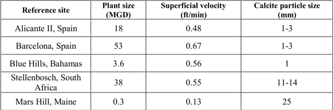
The Texas Water Treatment Board published a report on up-flow calcite contactor design in which they reported the design superficial velocities of calcite contactors for several different case studies. Table 2-3 is a summary of design superficial velocities and the particle size used in these studies (W. Walker, 2012). It is important to note that fine particles from calcite beds, which are dragged upstream, can influence the turbidity of the effluent which is a source of concern in drinking water treatment industry. Accordingly, if too many fines (< 80 micrometer) are present in the calcite media, turbidity is a source of concern because the relationship between superficial velocity and turbidity is highly dependent on the quality of the calcite. Figure 2.5. shows the relationship between turbidity and superficial velocities for calcite with two different kind of media consisting of less than 1 percent fines and with 2-3 percent fines. For the first sample (less than one percent of fines), turbidity starts to increase at around 15 meters per hour (m/hr) and for the second sample with 2-3 percent fines, turbidity starts to increase at around 11-12 m/h.
Table 2-3: Design superficial velocities and particle size used for calcite contactors in different case studies (Walker, 2012).
Reference site Plant size (MGD) Superficial velocity (ft/min) Calcite particle size (mm) Alicante II, Spain 18 0.48 1-3
Barcelona, Spain 53 0.67 1-3 Blue Hills, Bahamas 3.6 0.56 1
Stellenbosch, South
Africa 38 0.55 11-14 Mars Hill, Maine 0.3 0.13 25
Figure 2-5-Relationship between superficial velocity (m/h) and turbidity
As a brief conclusion based on the cited literature remark on the calcite dissolution rate, the dissolution is favored by:
• Lower feed water pH (increasing the CO2 concentration)
• Smaller particle size • Higher EBCT
• Lower temperature • Lower particle sphericity • Higher superficial velocity
2.2 Manganese removal
Manganese (Mn) is one of the emerging contaminants abundantly present in many water sources (Aziz & Smith, 1996; Franklin & Morse, 1983). In drinking water applications, manganese removal is a common treatment objective. The occurrence of manganese in drinking water gives rise to aesthetic and operational issues which increases the cost of cleaning or renewing fouled pipes (Tobiason et al., 2016). In addition, manganese is under review in Canada and the US for a possible health-based regulation given the increased evidence of its neurotoxicity, especially marked intellectual impairment in school-age children (Bouchard et al., 2011; Dion et al., 2018). Thus, efficient removal of Mn from drinking water is crucial. The United States Environmental Protection Agency (USEPA) (USEPA, 2004) has regulated the Secondary Maximum Contaminant Level (SMCL) of 0.05 mg/L for total manganese in drinking water. However, consumer complaints concerning aesthetic issues have been reported at concentrations as low as 0.02 mg/L (Sly et al., 1990). Consequently, Health Canada (Health-Canada, 2016) has recently proposed an aesthetic objective limit of 0.02 mg/L for total manganese in drinking water and 0.1 mg/L for health-based purposes. Therefore, it is recommended to keep the level of these minerals in drinking water as low as possible (Kenari, 2017).
2.2.1 Manganese removal options
Mn removal from drinking water sources can be carried out by different methods (Tobiason et al., 2016). A common treatment technique for Mn removal, applied in the municipal water treatment sector, is oxidation by a strong chemical (e.g. KMnO4) followed by precipitation and particle
removal (Kothari, 1988). As on-line chemical injection is challenging in small-scale applications, point-of-entry (POE) catalytic filtration with intermittent regeneration or POE cationic ion exchange (IX) coupled with point-of-use reverse osmosis are two widely implemented options to remove Mn in domestic applications (Carrière et al., 2011). However, the risk of Mn leaching from improperly operated catalytic filters, the high salt consumption for IX regeneration and the considerable amount of brine waste production, which pollutes the environment, are common drawbacks of these methods(Barbeau et al., 2011; Carrière et al., 2011).
Mn can also be removed from solution by sorption to a solid surface, manganese oxide (MnOx(s))
is the most often used media for Mn removal (Silva et al., 2012; Tobiason et al., 2016). As an alternative, recently, Haddad et al. (2018) proposed the use of back-washable hollow fiber nanofiltration (HFNF) membranes for the removal of Mn and Fe from groundwater (Haddad et al., 2018). The authors concluded that even though the application of the HFNF process could be an appealing solution for effective removal of Mn and Fe, non-selective rejection properties of the HFNF membrane would result in a corrosive permeate water. Therefore, the HFNF process should be coupled with a polishing step to adjust the hardness level of its soft permeate (Haddad et al., 2018). It should be noted that another interesting advantage of calcite lies in its ability to sorb divalent metallic cations (Me2+) on its surface (Aziz & Smith, 1996; Franklin & Morse, 1983). Due
removal from acid mine drainage (Aziz & Smith, 1992, 1996; Thornton, 1995; Zachara et al., 1991). It has also shown a greater efficiency over other media such as brick powder and gravel (Aziz & Smith, 1992, 1996; Thornton, 1995; Zachara et al., 1991). Therefore, calcite contactor could be a final polishing step for HFNF process to further reduce dissolved manganese which was not necessarily entirely rejected by the HFNF membrane process (Haddad et al., 2018). To achieve very high rejection of Mn with NF, one must select membranes with very low molecular weight cut-offs (<100 Da), a decision which imposes higher pressure of operation and/or lower productivity. The use of a limestone contactor after NF could offer the advantage of changing the selection of the NF membrane to more porous ones.
2.2.2 Sorption of manganese on calcite surface
Calcite-Mn interaction and particularly the fate of various phases in the complex system of CaCO3
-MnCO3-H2O has been well documented in the literature (Franklin & Morse, 1983; Kothari, 1988;
McBride, 1979; Pingitore et al., 1988; Silva et al., 2012; Thornton, 1995; Zachara et al., 1991). In 1979, McBride investigated the chemisorption of Mn2+ on calcite surface and proposed a reaction
mechanism, as shown through Eqs. 2-13 to 2-15. The author suggested that the quantity of Ca ions released to the water is very similar to the quantity of Mn2+ adsorbed on the surface, but this
phenomenon was not a direct displacement of ions, but rather the Mn2+ is sorbed on the surface as
MnCO3 which produces a proton that reacts with calcite to release Ca ions (McBride, 1979).
Furthermore, since no adsorption maximum is determined in these studies, it can be deduced that both precipitation-adsorption were involved in the interaction between Mn and calcite (McBride, 1979).
no%&+ q#)
*+® no#)*+ q& 2-13
q&+ #$#)
*® #$%&+ q#)*+ 2-14
The overall reaction mechanism proposed by McBride (1979) can be written as Eq. 2-15
no%&+ #$#)
*® no#)*+ #$%& 2-15
Apart from this, McBride also observed that Mn2+ adsorbed to the surface more than available
adsorption sites, based on unit cell size and area measurement. This further supported his assumption that both precipitation-adsorption were involved (McBride, 1979). Another interesting conclusion of McBride’s investigation was that at low Mn2+ concentrations (i.e., 0.1 mg Mn L-1)at
calcite surface, no discrete phase is formed but at higher concentrations, MnCO3 nucleation occurs
which is followed by a slow growth phase of MnCO3 (McBride, 1979). In 1982, Franklin and
Morse studied the interaction of Mn with the surface of calcite in dilute solutions and seawater. The authors concluded that Mn2+ is rapidly adsorbed to the surface, causing MnCO
3 nucleation
which is followed by a growth phase of MnCO3 by a first order reaction. However, in seawater
which contains high concentrations of Mg2+, the nucleation of MnCO
3 is inhibited because Mg2+
reach a critical concentration of MnCO3 nucleation (Franklin & Morse, 1983). In 2010, (Silva et
al., 2010) studied the interaction of Mn2+ and calcite during mine water treatment. The authors
claimed that the nucleation of the discrete phase of MnCO3 takes place at the surface of the calcite
media. By contrast, a number of researchers indicated that a dilute solid solution of Mn2+-CaCO 3
is formed at the surface due to the displacement of Mn2+ in the calcite matrix (Comans &
Middelburg, 1987; McBride, 1979; Pingitore et al., 1988). According to literature, the most commonly accepted kinetic for Mn and calcite interaction includes an initial rapid uptake of the trace metal (i.e., Mn) followed by a relatively slow formation of a solid solution expressed as Mn(x)Ca(1-x)CO3; where composition (x) changes gradually between the original solid and
precipitate of the sorbate which is gradually formed (Farley et al., 1985; McBride, 1979; Zachara et al., 1991). The initial rapid step is generally linked to an adsorption reaction while the following slow uptake is mainly attributed to the formation of solid solution and removal by precipitation at the surface. A number of researchers claimed that at low aqueous concentration (i.e., 0.1 mg Mn L-1), metals only incorporate into the surface of calcite by adsorption with no solid solution
formation (Comans & Middelburg, 1987; Franklin & Morse, 1983; McBride, 1979; Zachara et al., 1991). (Zachara et al., 1991) reported that metals with ionic radii smaller than Ca were more prone to sorb on calcite. Moreover, it should be noted that Mn2+ exhibits a very slow desorption rate
which favors the application of calcite for Mn sorption in the water treatment field (McBride, 1979; Zachara et al., 1991).
According to Stumm and Morgan (1995), it is also possible to have other species in pH ranges 8-10 (Fig. 2-6). Although the possibility of MnCO3 formation is higher than other species in the
mentioned pH range, given the potential of feed water used in the above-mentioned studies (-0.5 - 0.5), the presence of oxides and hydroxides is also possible. However, characterization of filter media coating is crucial to better understand the driving force behind high efficiency of manganese removal in elevated Mn concentrations.
Figure 2-6: potential (E h in V) as a function of the pH showing the stability zones of manganese-containing compounds in aqueous solution. Source: adopted from Stumm and Morgan (1970)
2.2.3 Models describing Mn sorption on calcite surface
Modeling divalent metals sorption on carbonate minerals has received considerable attention over the last decades, including the modeling of Mn sorption on the surface of calcite (Comans & Middelburg, 1987; Farley et al., 1985). Surface precipitation model (SPM) and surface complexation model (SCM) are the two main modeling approaches used to describe the sorption of divalent metals on calcite. In the former model, it is considered that the precipitation on the solid is based on solid solution formation where the composition of the newly formed solid solution is continuously changing between that of the original solid and the precipitated sorbate layer (Farley et al., 1985; Mettler et al., 2009). (Comans & Middelburg, 1987) investigated the SPM model applicability to describe the sorption of divalent metals on calcite and proposed a continuum between adsorption and precipitation for Mn2+ sorption on calcite. According to (Zachara et al.,
1991) findings, adsorption constants for different divalent metals in SPM are ranked based on the degree for which the ionic radius of the sorbate matches the ionic radius of Ca2+. It is worth
mentioning that SPM was also successfully applied for modeling Mn2+ sorption on siderite (FeCO 3)
surface (Wersin et al., 1989). The Surface Complexation Model (SCM), on the other hand, is based on an initial rapid adsorption step followed by surface complexation prior to the precipitation of MeCO3 and dilute solid solution formation. Three common versions of the SCM model have been
used to describe metal ion adsorption on pure mineral materials: constant capacitance model (CCM), diffuse layer model (DLM), and triple layer model (TLM) (Wen et al., 1998).
2.3 Knowledge gap based on the literature review
Despite the fact that there are several comprehensive studies addressing both the implementation of calcite contactors in the water industry as a simple and reliable remineralization and corrosion control technique and Mn adsorption on the surface of calcite, the integration of both processes to a single stage process has not received enough attention. Furthermore, to the best of our knowledge, the significance and fate of sorbed Mn and its impact on the overall performance of a calcite contactor in a long-term operation has not been addressed yet. In this regard, the primary goal of this research effort is to determine the detrimental effect of Mn-coating on calcite dissolution rate and eventually model the long-term behavior of a calcite contactor operated for simultaneous drinking water remineralization and Mn removal. The outcome of this study would enable us to design a simple, yet robust system for an efficient treatment of domestic GW supplies.
RESEARCH OBJECTIVES, HYPOTHESES AND
METHODOLOGY
3.1 Objectives and hypotheses
3.1.1 General objectiveThe main objective of this research effort is to design a calcite contactor as a reliable and simple method for polishing the soft permeate of HFNF process. This polishing step will simultaneously remineralize the soft permeate and reduce dissolved manganese which was not necessarily entirely rejected by the HFNF process (target of 0.02 mg Mn/L and 40 mg CaCO3/L as hardness in treated
water).
3.1.2 Specific objectives
On a more detailed basis, the following specific objectives can be defined:
• Determine the role of the media specifications (i.e., use of pure calcite (CaCO3) or a blend
of calcite and CorosexTM (MgO));
• Screen the best operational conditions for the efficient operation of a calcite contactor as a polishing step (i.e., temperature, EBCT, …);
• Investigate the significance and fate of sorbed Mn on the overall performance of a calcite contactor in long-term operation;
• Model the long-term behavior of a calcite contactor operated for drinking water remineralization.
3.1.3 Research hypotheses
• Mn sorption on calcite surface is reduced at lower temperature and higher EBCT;
• Mn coating on the calcite surface decreases the rate at which calcium carbonate dissolves into the water;
• A small portion of CorosexTM media mixed with calcite can remineralize the water to above
• A simple calcite dissolution rate based on calcite saturation index can be used to predict the long-term behavior of a calcite contactor with respect to calcite dissolution in the presence of manganese coating.
3.2 Methodology
The experimental approach was conducted in four main parts consisting of three experimental phases and one modeling phase:
1) In the first phase, the impact of initial Mn2+ concentration was investigated by means of
continuous sorption-dissolution experiments. In this regard, we determined the overall performance of a calcite contactor in the removal of Mn and remineralization of SFW using two initial concentrations of Mn (i.e., 0.5 and 5 mg Mn L-1).
2) Based on the results of the first phase, the objective of the second phase was to investigate the effect of Mn loading on calcite dissolution rate using continuous dissolution experiments. To this end, we transferred the loaded media from the loaded column used for the first phase to four mini-columns and operated them for five days in a continuous mode. 3) As for the third phase, the long-term efficiency of a calcite contactor was modeled based on calcite dissolution and Mn sorption/precipitation. The model was implemented in PHREEQC and it was used to investigate the long-term efficiency of a calcite contactor. 4) In the final phase, as we were not able to obtain the sought treated water characteristics
with only calcite media, a blend of calcite (i.e., calcium carbonate), mixed with magnesium oxide (MgO) was used to achieve both goals of remineralization and partial Mn removal. In what follows, the experimental protocol for each part is elaborated upon:
3.2.1 Continuous sorption-dissolution experiments with calcite media
3.2.1.1 Characteristics of synthetic feedwater (SFW) and calcite media
Synthetic feed water (SFW) was prepared by dissolving powdered reagent grade (>99% pure) MnSO4 (Fisher Scientific, NJ, USA) in ultra-pure (i.e., Milli-Q™) water. Commercially available
calcite (2.68 g/cm3) media was purchased from Imerys Marble Inc, Sahuarita, AZ, USA. To
determine the particle size distribution and accordingly the representative diameter of the grains, sieving analysis was executed on calcite media. The Fig. 3.1. demonstrates the results of sieving analysis and based on the results, the median diameter (D50) of 0.40 mm was chosen as the
representative diameter for future calculations. As the calcite grains were highly homogeneous, the D50 value is equal to average diameter of the grains (D10) reported by Imerys Marble Inc, Sahuarita,
Table 3-1: Calcite media characteristics
(1) Measured in the laboratory using sieving
(2) Determined by Inductively Coupled Plasma-Optical Emission Spectrometry (ICP-OES, model iCAP 6000, Thermo Instruments Inc) after nitric acid acidification
(3) Provided by the supplier (Imerys Marble Inc, Sahuarita, AZ, USA)
(4) Data provided via BET measurement (The BET procedure is described in (Gambou-Bosca & Bélanger, 2016))
Figure 3-1: The size distribution curve for grain size ranging between 0.2-0.7


![Figure 2-4: Average [Ca 2+ ] in the calcite reactor as a function of retention time for the six case](https://thumb-eu.123doks.com/thumbv2/123doknet/2344570.34607/31.918.252.674.332.581/figure-average-calcite-reactor-function-retention-time-case.webp)