HAL Id: tel-01511683
https://tel.archives-ouvertes.fr/tel-01511683
Submitted on 21 Apr 2017
HAL is a multi-disciplinary open access
archive for the deposit and dissemination of sci-entific research documents, whether they are pub-lished or not. The documents may come from teaching and research institutions in France or abroad, or from public or private research centers.
L’archive ouverte pluridisciplinaire HAL, est destinée au dépôt et à la diffusion de documents scientifiques de niveau recherche, publiés ou non, émanant des établissements d’enseignement et de recherche français ou étrangers, des laboratoires publics ou privés.
by temperature fields in rarefied gas : application to the
design of Knudsen micropumps
Jie Chen
To cite this version:
Jie Chen. Numerical and experimental analysis of flows generated by temperature fields in rarefied gas : application to the design of Knudsen micropumps. Mechanics of the fluids [physics.class-ph]. INSA de Toulouse, 2016. English. �NNT : 2016ISAT0009�. �tel-01511683�
THÈSE
En vue de l'obtention duDOCTORAT DE L’UNIVERSITÉ DE TOULOUSE
Délivré par Institut National des Sciences Appliquées de Toulouse (INSA de Toulouse) Discipline ou spécialité : Énergétique et transferts
Présentée et soutenue par Jie CHEN Le lundi 21 mars 2016
Titre :
Numerical and experimental analysis of flows generated by temperature fields in rarefied gas: application to the design of Knudsen micropumps
JURY
Aldo FREZZOTTI, Professeur à l’École Polytechnique de Milan, Rapporteur Gian Luca MORINI, Professeur à l'Université de Bologne, Rapporteur
Stéphane COLIN, Professeur à l'INSA de Toulouse, Examinateur
Lucien BALDAS, Maître de conférences, HDR à l'INSA de Toulouse, Examinateur Juergen BRANDNER, Professeur à Karlsruhe Institute of Technology, Examinateur
Irina GRAUR, Professeur à Université d’Aix-Marseille, Examinateur
Stefan KANCHEV STEFANOV, Professeur à Bulgarian Academy of Sciences, Examinateur
Ecole doctorale : MEGEP
Unité de recherche : Institut Clément Ader
“学而不思则罔,思而不学则殆”
——《论语•为政》
Learning without thought is labour lost,
thought without learning is perilous.
Acknowledgements
I would like to gratefully and sincerely thank my supervisors, Stephane Colin and Lucien Baldas, for their guidance, patience and continuous support of my Ph.D research in INSA Toulouse. Besides being a preeminent researcher in microfluidics, Prof. Stephane Colin is also an excellent advisor, who gave me the opportunity to fully develop my individuality. Associate Prof. Lucien Baldas, outstanding researcher in flow control research field, also gave me great suggestions on my topic. They gave me advices and help in a lot of aspects, from living in France to doing research. I benefited from my supervisors not only in their immense scientific knowledge, but also rigorous scholarship and modesty. I feel very honored and lucky to do my Ph.D research under their supervision. I am also very grateful to professor Stefan K Stefanov for his help and guidance on direct simulation Monte Carlo.
I would like to thank the defense committee: Prof. Aldo Frezzotti, Prof. Gian Luca Morini, Prof. Stefan K Stefanov, Prof. Juergen Brandner, Prof. Irina Graur, for their encouragement, insightful comments, and interesting questions.
I would also like to thank all of the members of the group of microfluidics and they gave me lots of help during my Ph.D study. I am very grateful to Marcos Rojas-Cardenas and Christine Barrot for very useful discussions and technical advices on experiments. I would like to give my special thanks to Nicolas Laurien for helping with the construction of the new experimental set-up. I also thank Pascale Magaud, Hacene Si Hadj Mohand, Dominique Fratantonio, Ernane Silva for interesting talks on science and nature in those coffee breaks.
I would also like to thank the members of Institut Clément Ader and Ecole Doctorale MEGeP. I enjoyed my research experiences at Institut Clément Ader with those outstanding researchers. Additionally, I am very grateful for the friendship with other Ph.D students in my laboratory, especially Hacene Si Hadj Mohand, Jean-Emmanuel Chambe, Ksentini Olfa, Shiqi Wang, Jian Fu, Yiwei Wang, Yanfeng Gao, Donghai Qiu and Tao Li.
I acknowledge the scholarship of China Scholarship Council (CSC) which awarded a scholarship for my studies in France.
Their love, support and encouragement provide me endless power and energy to pursue my scientific dream.
Abstract
This thesis presents a numerical and experimental analysis of internal rarefied gas flows induced by temperature fields. In rarefied gases, a flow can be generated by solely applying a tangential temperature gradient along a wall: without any initial pressure gradient, the gas macroscopically moves from the cold toward the hot region. This phenomenon is the so-called thermal creep or thermal transpiration effect. It is the main operating principle of the Knudsen pump, which can generate gas pumping without the need of any moving parts. The main aspect of this work is centered on numerical investigations of thermal transpiration flows in three new possible configurations of Knudsen pumps. For that goal, a numerical model for slip flows has been developed in which the appropriate slip boundary conditions are implemented in a commercial CFD code and a DSMC code has been adapted for studying transition flows in complex geometries. The pumping effect of curved-channel Knudsen pumps, the thermal transpiration flows through tapered channels and between two ratchets surfaces at different uniform temperatures have been investigated. In addition, an experimental study of thermal transpiration flow through a single micro-tube has been carried out on a new experimental set-up designed to be adaptable for testing thermally driven flows through various kinds of microchannels or generated by autonomous Knudsen compressors.
Keywords: Microfluidics, gas microflows, thermal transpiration, Knudsen pump, CFD, DSMC
Cette thèse présente une étude numérique et expérimentale d’écoulements gazeux raréfiés confinés induits par gradients thermiques ainsi que trois nouvelles configurations de pompe Knudsen.
En raison de la tendance à la miniaturisation des systèmes électromécaniques, des micropompes à gaz sont nécessaires notamment pour une large gamme de microsystèmes de détection et d'analyse, tels que les nez électroniques, les spectromètres de masse ou encore les chromatographes en phase gazeuse (Pham-Van-Diep et al. 1995). L'une des pompes à vide miniaturisées les plus attrayantes est la pompe Knudsen qui fonctionne sur le principe de la transpiration thermique (Vargo et al. 1999). Après avoir analysé divers microsystèmes impliquant des écoulements gazeux confinés, il apparait clairement que les effets de raréfaction qui résultent de la réduction de taille de l'appareil ne peuvent pas, dans presque tous les cas, être négligés (Colin 2013). L'un des paramètres les plus couramment utilisés pour caractériser le niveau de raréfaction est le nombre de Knudsen qui est défini par le rapport du libre parcours moyen des molécules de gaz (c'est-à-dire la distance moyenne parcourue entre deux collisions successives) à une longueur interne caractéristique du système. Le nombre de Knudsen permet une classification des régimes d'écoulement gazeux. En général, quatre régimes d'écoulement gazeux sont considérés : le régime continu, le régime d'écoulement glissant, le régime de transition et le régime moléculaire libre. Des modèles appropriés doivent être choisis en fonction du régime d'écoulement rencontré.
L’écoulement d’un gaz raréfié peut être généré simplement en appliquant un gradient tangentiel de température le long d'une paroi. Ainsi, sans gradient initial de pression, le gaz peut se déplacer de la région froide vers la région chaude. Ce phénomène, appelé transpiration thermique, est à la base du fonctionnement de la pompe Knudsen qui est capable de générer un pompage du gaz sans utiliser de pièces mécaniques mobiles. Plusieurs modèles différents de pompes Knudsen ont été étudiés au cours des dernières années, à la suite du travail fondateur de Knudsen lui-même (Knudsen 1909). La pompe Knudsen typique est basée sur un système en cascade dans lequel une unité de base se compose d'un micro-canal (McNamara et al. 2005, Gupta et al. 2012, An et al. 2014) ou d'un milieu microporeux (Han et al. 2007, Gupta et al. 2011) reliant deux mini chambres à températures différentes. D'autres configurations ont été proposées et étudiées numériquement,
cependant, la difficulté pratique principale provient de la nécessité de contrôler précisément le gradient de température le long des parois.
L’apport principal de ce travail est relatif à l’étude numérique de l’écoulement de transpiration thermique dans trois nouvelles configurations de pompe Knudsen.
Dans ce but, une méthode numérique pour la simulation d’écoulements dans le régime de glissement a été développée ; elle implémente des conditions aux limites de saut de vitesse et de température spécifiques à l'aide de "User Defined Functions" (UDF), dans un code CFD commercial. Par rapport aux méthodes cinétiques ou aux simulations de type Monte-Carlo (DSMC), ce modèle a un coût de calcul largement réduit, ce qui facilite la conception et l'optimisation des pompes, du point de vue de la géométrie et des conditions de fonctionnement. Parallèlement, un code DSMC a été mis en œuvre pour étudier des écoulements plus fortement raréfiés dans les géométries les plus complexes. Grâce à ces modèles numériques, des écoulements de transpiration thermique générés dans des canaux courbes, dans des canaux convergents/divergents ou entre deux surfaces spécialement micro-texturées ont ainsi été étudiés. Les simulations numériques ont montré qu'une pompe Knudsen à plusieurs étages constitués de canaux courbes et droits en alternance peut être efficace dans le régime d'écoulement glissant. Une analyse paramétrique menée sur un étage unique de cette pompe Knudsen a permis d'élaborer des lignes directrices pour améliorer l'efficacité de la pompe qui doit avoir une partie semi-circulaire de forte courbure et devrait fonctionner sous une différence de température élevée et dans des conditions de raréfaction assez fortes. Un premier prototype d'une pompe Knudsen de ce type à l'échelle millimétrique, comprenant 50 étages, a été conçu et fabriqué à l'Institut de Technologie de Karlsruhe (KIT) et ses performances ont été estimées numériquement sur la base d'une configuration 2D simplifiée. Ce prototype sera examiné expérimentalement dans le futur à l'aide d'un nouveau banc expérimental lorsque les problèmes d'étanchéité au niveau de la structure et des raccords auront été résolus.
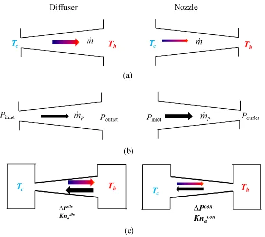
L'analyse des écoulements de transpiration thermique dans des canaux coniques a montré qu'un effet diode existe dans les canaux divergents / convergents soumis à un gradient de température.
démontre également la possibilité de concevoir une pompe Knudsen à base de canaux coniques en profitant de cet effet diode. Par rapport aux modèles classiques, cette pompe Knudsen présente plusieurs avantages importants en termes de conception et de contrôle des contraintes thermiques. Une nouvelle configuration de pompe Knudsen, qui ne nécessite que des parois isothermes, chaudes ou froides, et qui par conséquent est beaucoup plus facile à contrôler thermiquement qu'une pompe classique nécessitant un gradient de température le long d'une surface, a été étudiée par des simulations CFD basées sur l’approche continue ainsi que par des calculs DSMC. L'élément de pompage est constitué de deux surfaces en dents de scie asymétriques, isothermes et à températures différentes, se faisant face. Un débit massique net a été observé et le fonctionnement de ce nouveau type de pompe Knudsen a été prouvé numériquement. L'influence des principaux paramètres géométriques et des conditions de fonctionnement, comme le nombre de Knudsen et la différence de température, a été étudiée et des lignes directrices pour la conception d'un prototype ont été élaborées.
D’autre part, un nouveau dispositif expérimental a été conçu pour l'étude des écoulements de transpiration thermique dans différents types de canaux ainsi que pour le test de micro-pompes Knudsen. Les premières données expérimentales obtenues pour un écoulement de transpiration thermique dans un micro-tube ont été comparées avec succès, pour un petit nombre de Knudsen, à un modèle théorique d'écoulement glissant, ce qui a permis la validation du banc d'essais.
Mots-Clés : Microfluidique, micro-écoulements gazeux, transpiration thermique, pompe Knudsen, CFD, DSMC
Références :
An, S., Gupta, N. K. and Gianchandani, Y. B. (2014). "A Si-micromachined 162-stage two-part Knudsen pump for on-chip vacuum." Journal of Microelectromechanical Systems 23(2): 406-416.
Computational Physics 6(5): 911-954.
Bond, D. M., Wheatley, V. and Goldsworthy, M. (2016). "Numerical investigation into the performance of alternative Knudsen pump designs." International Journal of Heat and Mass Transfer 93: 1038-1058.
Colin, S. (2013). Single-phase gas flow in microchannels. Heat transfer and fluid flow in minichannels and microchannels, Elsevier: 11-102.
Gupta , N. K., An, S. and Gianchandani, Y. B. (2012). "A Si-micromachined 48-stage Knudsen pump for on-chip vacuum." Journal of Micromechanics and Microengineering 22(10): 105026.
Gupta, N. K. and Gianchandani, Y. B. (2011). "Porous ceramics for multistage Knudsen micropumps—modeling approach and experimental evaluation." Journal of Micromechanics and Microengineering 21(9): 095029.
Han, Y.-L., Phillip Muntz, E., Alexeenko, A., et al. (2007). "Experimental and Computational Studies of Temperature Gradient–Driven Molecular Transport in Gas Flows through Nano/Microscale Channels." Nanoscale and Microscale Thermophysical Engineering 11(1-2): 151-175.
Knudsen, M. (1909). "Eine Revision der Gleichgewichtsbedingung der Gase. Thermische Molekularströmung." Annalen der Physik 336(1): 205-229.
McNamara, S. and Gianchandani, Y. B. (2005). "On-Chip Vacuum Generated by a Micromachined Knudsen Pump." Microelectromechanical Systems, Journal of 14(4): 741-746.
Pham-Van-Diep, G., Keeley, P., Muntz, E. P., et al. (1995). "A micromechanical Knudsen compressor." Rarefied gas dynamics 1: 715-721.
Vargo, S., Muntz, E. and Tang, W. (1999). The MEMS Knudsen Compressor as a Vacuum Pump for Space Exploration Applications. 2nd International Conference on Integrated Micro/Nanotechnology for Space Applications. Pasadena, California, USA.
Nomenclature……….…...i
Introduction……….…1
Chapter 1 Thermal transpiration flows and Knudsen pumps……….………...5
1.1. Thermal transpiration flow ... 5
1.1.1. Fundamental demonstration of flow induced by temperature fields ... 7
1.1.2. Quantitative measurements on thermal transpiration flow ... 9
1.1.3. Analytical and numerical investigations ... 14
1.2. Knudsen pumps ... 15
1.2.1. Knudsen pumps with nanoporous materials ... 15
1.2.2. Knudsen pumps with micromachined channels ... 17
1.2.3. Knudsen pumps in laboratory conditions and experimental set-ups .... 18
References ... 21
Chapter 2 Modeling of thermal transpiration flow………...…………...…...25
2.1. General points about gas microflows modeling ... 25
2.1.1. The simple dilute gas ... 25
2.1.2. Molecular collision models ... 26
2.1.3. Thermodynamic equilibrium ... 30
2.1.4. Gas flow regimes and main models ... 30
2.2. Slip flow regime ... 31
2.2.1. Boundary conditions ... 31
2.2.2. Analytical method ... 34
2.2.3. Numerical method ... 37
2.3. Transitional regime - DSMC simulation... 45
2.3.1. DSMC simulation ... 45
2.3.4. Validation: thermally-driven flow in a closed rectangular channel ... 48
2.4. Summary ... 50
References ... 50
Chapter3 Thermal transpiration flow in tapered channels….…….……...…...53
3.1. Introduction ... 53
3.2. Isothermal flow ... 55
3.3. Thermal transpiration flow ... 57
3.3.1. Mass flowrate at constant pressure (open reservoir configuration) .... 59
3.3.2. Pressure difference at zero mass flowrate (closed reservoir configuration at equilibrium) ... 61
3.3.3. Tapered-channel Knudsen pump ... 65
3.4. Summary ... 68
References ... 68
Chapter 4 Curved-channel Knudsen pumps………...………...71
4.1. Introduction ... 71
4.2. Numerical design ... 73
4.2.1. Simulation of multi-stage pumps ... 73
4.2.2. Parametric analysis of a single-stage micropump ... 76
4.3. A prototype of serpentine Knudsen pump ... 85
4.3.1. Description of the pump system ... 85
4.3.2. Numerical estimation of performance ... 86
4.4. Summary ... 91
References ... 91
Chapter 5 Ratchet Knudsen pumps 5.1. Introduction ... 93
5.2. Study in the slip flow regime ... 96
5.2.1. Problem statement ... 96
5.2.4. Parameter analysis ... 101
5.3. DSMC Simulation ... 107
5.3.1. Problem statement ... 107
5.3.2. Reference configuration ... 108
5.3.3. Temperature distribution and flow characteristics ... 109
5.3.4. Influence of the Knudsen number ... 112
5.3.5. Influence of the accommodation coefficients ... 116
5.3.6. Influence of geometric parameters ... 118
5.3.7. Decomposition solution into ballistic and collision parts ... 121
5.4. Summary ... 123
References ... 124
Chapter6 Experimental study of thermal transpiration flow through a microtube………...………..127
6.1. Description of the experiment set-up ... 127
6.1.1. Test section ... 128
6.1.2. Measurement ring ... 129
6.1.3. Temperature control and measurements ... 131
6.2. Measurement procedure ... 135
6.3. Results and discussion ... 136
6.3.1. Final equilibrium state ... 136
6.3.2. Analysis of the unsteady pressure variation process ... 138
6.4. Summary ... 145
References ... 145
i
Nomenclature
Symbols
a Microtube radius (m)
Α Area normal vector P
A Amplitude of pressure fluctuation (Pa) *
P
A Fluctuating pressure gain
b Intermolecular distance (m)
'
c Mean thermal velocity (m s1) r
c Relative velocity between two molecules ( 1 m s )
d Mean molecular diameter (m) (Chapter 2)
d Ratchet height (m) (Chapter 5)
D Tube diameter (m)
h
D Hydraulic diameter (m)
E Diode efficiency N
F Number of real molecules represented by a simulator in DSMC
P
G Pressure gain
G Density gain
h Heat transfer coefficient (W m K2 1) (Chapter 6)
h Distance between two ratchet surfaces (m) (Chapter 5)
H Channel height (m)
j
I Simulator indicator
k Boltzmann constant (1.381 10 23 J K1) 2
k Mean free path coefficient
ii
L Channel length (m)
c
L Characteristic length (m) m
L Misalignment distance in ratchet pumps (m) s
L Length of channel straight part in curved-channel Knudsen pump (m)
s
L Length of channel centerline of the curved part in curved-channel
Knudsen pump (m) t
L Total channel length in curved-channel Knudsen pump (m)
sv
L Characteristic length of a sampling volume (m)
z
L Length of heating/cooling zone (m)
m Molecular mass (kg) M Molecular weight ( 1 kg mol ) m Mass flowrate ( 1 m s ) n Number density ( 3 m )
n Coordinate in the direction normal to the wall (m)
N Number of test molecules in a DSMC cell
s
N Number of pump stages NTC
N Maximum number of collisions in a DSMC cell
p Dimensionless logarithmic pressure gradient
s
p Perimeter (m)
P Pressure (Pa)
Pr Prandtl number
q Average volume flowrate (m s3 1)
q Heat flux ( 2
W m ) P
iii
T
Q Dimensionless temperature driven volume flowrate
r Curvature radius (m)
R Specific gas constant (J kg K1 1)
c
R Radius of curvature in serpentine Knudsen pump (m)
1
R Radius of inner cylinder (m)
2
R Radius of outer cylinder (m)
s Coordinate in the direction tangent to the wall (m)
S Cross-sectional area ( 2 m )
t Time (s)
T Temperature (K)
c
T Cold temperature (K) in a reservoir, on a surface or at a point h
T Hot temperature (K) in a reservoir, on a surface or at a point
TPD Thermomolecular pressure difference (Pa)
TPR Thermomolecular pressure ratio
s u Tangential velocity ( 1 m s ) n u Normal velocity (m s1) V Volume of a reservoir ( 3 m ) W Channel width (m) z Axial coordinate (m) Greek Symbols
Collision coefficient for VSS model v
Tangential momentum accommodation coefficient T
Thermal accommodation coefficient I
iv
V
Accommodation coefficient of vertical wall for ratchet surface
Ratchet angle (°)
Dimensionless ratio of temperature over pressure variations Specific heats ratio
Dynamic viscosity (Pa s)
Index relating pressure and temperature ratios P
Viscous slip coefficient T
Thermal slip coefficient t
Total collision cross-section ( 2 m )
T
Temperature jump coefficient Mean free path (m)
e
Equivalent mean free path (m) g
Thermal conductivity ( 1 1 W m K ) Mean molecular spacing (m)
Gas density ( 3
kg m )
Time constant (s) wall
Shear stress at the wall (Pa)
Dimensionless logarithmic temperature gradient (Chapter 1)
Angle between Cartesian and local coordinate systems (rad) (Chapter 2)
Mean collision rate ( 1 s ) Angle of tapered channel (°) Heat rate per unit volume (W m3)
s
Heat rate (W)
Collision coefficient for VHS or VSS model 1
Angular velocity of a cylinder ( 1 rad s )
v
Deflection angle (rad)
Acronyms
BGK Bhatnagar–Gross–Krook CFD Computational Fluid Dynamics DSMC Direct Simulation Monte Carlo
HS Hard Sphere
LPBS Low Pressure Boundary Slip NTC No Time Counter
TMAC Tangential Momentum Accommodation Coefficient UDF User Defined Function
VHS Variable Hard Sphere VSS Variable Soft Sphere
- 1 -
Gas Microflows
Due to the trend of miniaturization of electromechanical systems, gas micropumps are required in a wide range of sensing and analysis related microsystems, such as electronic noses, mass spectrometers, gas chromatographs (Pham-Van-Diep et al. 1995). One of the attractive candidates of miniaturized vacuum pump is the Knudsen pump which operates according to the thermal transpiration effect (Vargo et al. 1999). After analyzing various microsystems involving confined gas flow, it is clear that the rarefaction effects which result from shrinking down the device size cannot, in almost every case, be neglected (Colin 2013). One of the most commonly used parameters chosen to characterize the rarefaction level is the Knudsen number Kn which is defined as the ratio of the mean free path of the gas molecules (i.e., the average distance travelled between two successive collisions) to the internal characteristic length L of the system. The Knudsen number allows a classification of the gas flow regimes. In general, four different types of gas flow regimes –continuum, slip, transitional, and free molecular– are considered. The appropriate methods must be chosen according to the encountered flow regime.
Thermal transpiration flows and Knudsen pumps
In rarefied gases, flows can be generated by a tangential temperature gradient along a wall, without any initial pressure gradient. This well-known phenomenon is the so-called thermal creep, or thermal transpiration, effect. This phenomenon was first analyzed independently by Reynolds (Reynolds 1879) and Maxwell (Maxwell 1879) in 1879. The thermal transpiration is the basis of the Knudsen pump operation principle: it allows gas pumping without any moving part when the gas is under rarefied conditions, either due to small dimensions or to low pressures. Several different designs of Knudsen pumps have been studied in the past years, following the seminal work of Knudsen itself (Knudsen 1909). The typical Knudsen micropump is based on a cascade system in which a basic unit is composed of a microchannel (McNamara et al. 2005, Young et al. 2005, Gupta et al. 2012, An et al. 2014) or of a
- 2 -
microporous medium (Han et al. 2007, Gupta et al. 2011) connecting two mini chambers with different temperatures. Alternative configurations have been proposed and numerically studied, consisting of alternately connected curved and straight microchannels (Aoki et al. 2009) or curved microchannels with different curvature radii (Bond et al. 2016). In these designs, however, the main practical difficulty comes from the necessity to accurately control the temperature gradient generated along the walls.
Structure of the thesis manuscript
The present thesis is devoted to the investigation of thermal transpiration flows using analytical and numerical approaches as well as experimental measurements, with a view to an application to the design of novel Knudsen pumps, more efficient and/or easier to manufacture and control.
In Chapter 1, the thermal transpiration phenomenon and the derived Knudsen pumps are introduced by reviewing the main works published in the literature on this subject. Recently reported prototypes of Knudsen pumps using nanoporous materials or etched microchannels are introduced. The main limitations of the already studied Knudsen pump configurations are summarized and current needs of efficient numerical tools and accurate experimental data are highlighted.
In Chapter 2, several basic concepts -including the dilute gas assumption and molecules collision models required for modeling rarefied gas microflows- are firstly introduced and the models developed in this work for slip and transition flows are presented. A numerical method using the CFD code ANSYS Fluent®, in which User Defined Functions (UDF) are implemented to simulate accurate boundary conditions are developed. Finally, the DSMC method is introduced and an open source code named dsmcFoamStrath, as well as a code allowing a novel decomposition of the solution into ballistic and collision parts, are presented.
Chapter 3 presents a numerical investigation of thermal transpiration flows in tapered microchannels. An isothermal pressure-driven flow through a tapered channel is first studied and the numerical results are compared with existing experimental data. Then the thermal transpiration flow in convergent and divergent channels is investigated and the observed diode effect is analyzed. With a principle based on this
- 3 - diode effect, a novel Knudsen pump with tapered channels is proposed and numerically tested.
Chapter 4 presents a numerical design of a serpentine Knudsen pump, the principle of which is based on the transpiration effect in curved and straight channels in the slip flow and early transition regimes. This pump is constructed by alternatively connecting a series of curved and straight channels with the same uniform cross-section. A parameter analysis for a single-stage micropump and the performance of multi-stage micropumps are presented. A first prototype of a multi-stage curved-channel Knudsen pump at millimetric scale designed and fabricated at the Karlsruhe Institute of Technology is presented and its performances are evaluated through a series of numerical simulations.
In Chapter 5, the performance of a new type of Knudsen pump, which only requires isothermal hot or cold walls and is consequently much easier to control than a classic pump with temperature gradient along a surface, is investigated. The pumping element consists of two facing isothermal ratchet surfaces with different uniform temperatures. The asymmetric saw-tooth like surfaces leads to a rectified Knudsen flow along the walls. A numerical investigation with both CFD and DSMC simulations is presented.
Chapter 6 presents a new experimental set-up for investigating a thermal transpiration flow through a single micro-tube. The experimental apparatus has been designed to be adaptable for investigating various channel configurations as well as autonomous Knudsen compressors. The experimental set-up and the experimental procedure are detailed. Then the first experimental results are shown and discussed with comparison to theoretical data.
Finally, conclusions and perspectives of this work are proposed at the end of the manuscript.
References
An, S., Gupta, N. K. and Gianchandani, Y. B. (2014). "A Si-micromachined 162-stage two-part Knudsen pump for on-chip vacuum." Journal of Microelectromechanical Systems 23(2): 406-416.
Aoki, K., Degond, P. and Mieussens, L. (2009). "Numerical simulations of rarefied gases in curved channels: thermal creep, circulating flow, and pumping effect." Communications in Computational Physics 6(5): 911-954.
- 4 -
Bond, D. M., Wheatley, V. and Goldsworthy, M. (2016). "Numerical investigation into the performance of alternative Knudsen pump designs." International Journal of Heat and Mass Transfer 93: 1038-1058.
Colin, S. (2013). Single-phase gas flow in microchannels. Heat transfer and fluid flow in minichannels and microchannels, Elsevier: 11-102.
Gupta , N. K., An, S. and Gianchandani, Y. B. (2012). "A Si-micromachined 48-stage Knudsen pump for on-chip vacuum." Journal of Micromechanics and Microengineering 22(10): 105026.
Gupta, N. K. and Gianchandani, Y. B. (2011). "Porous ceramics for multistage Knudsen micropumps—modeling approach and experimental evaluation." Journal of Micromechanics and Microengineering 21(9): 095029.
Han, Y.-L. and Muntz, E. P. (2007). "Experimental investigation of micro-mesoscale Knudsen compressor performance at low pressures." Journal of Vacuum Science & Technology B: Microelectronics and Nanometer Structures 25(3): 703-714.
Knudsen, M. (1909). "Eine Revision der Gleichgewichtsbedingung der Gase. Thermische Molekularströmung." Annalen der Physik 336(1): 205-229.
Maxwell, J. C. (1879). "On stresses in rarefied gases arising from inequalities of temperature." Phil. Trans. R. Soc. 170: 231-256.
McNamara, S. and Gianchandani, Y. B. (2005). "On-Chip Vacuum Generated by a Micromachined Knudsen Pump." Microelectromechanical Systems, Journal of 14(4): 741-746.
Pham-Van-Diep, G., Keeley, P., Muntz, E. P., et al. (1995). "A micromechanical Knudsen compressor." Rarefied gas dynamics 1: 715-721.
Reynolds, O. (1879). "On Certain Dimensional Properties of Matter in the Gaseous State. Part I. Experimental Researches on Thermal Transpiration of Gases through Porous Plates and on the Laws of Transpiration and Impulsion, Including an Experimental Proof That Gas is Not a Continuous Plenum. Part II. On an Extension of the Dynamical Theory of Gas, Which Includes the Stresses, Tangential and Normal, Caused by a Varying Condition of Gas, and Affords an Explanation of the Phenomena of Transpiration and Impulsion." Philosophical Transactions of the Royal Society of London 170: 727-845. Vargo, S., Muntz, E. and Tang, W. (1999). The MEMS Knudsen Compressor as a Vacuum
Pump for Space Exploration Applications. 2nd International Conference on Integrated Micro/Nanotechnology for Space Applications. Pasadena, California, USA.
Young, M., Han, Y. L., Muntz, E. P., et al. (2005). "Characterization and Optimization of a Radiantly Driven Multi ‐Stage Knudsen Compressor." AIP Conference Proceedings 762(1): 174-179.
- 5 -
Chapter 1
Thermal transpiration flows and Knudsen pumps
In this chapter, the thermal transpiration phenomenon and the derived Knudsen pumps are introduced by reviewing the main works published in the literature on this subject. The thermal transpiration phenomenon was first observed by Reynolds in the early 1900s and a series of works have followed this seminal observation, including experimental measurements as well as analytical and numerical investigations. Meanwhile, since 1909 when Knudsen reported the first gas pump based on the transpiration phenomenon, various researchers have contributed to the development of the so-called Knudsen pumps. Some of these pumps have been constructed using porous materials and micromachined Knudsen pumps were also recently reported and experimentally tested.
1.1. Thermal transpiration flow
In rarefied gases, i.e. in low pressure and/or highly confined configurations, flows can be generated by only a tangential temperature gradient applied along a wall, without any initial pressure gradient. This now well-known phenomenon is the so-called thermal creep, or thermal transpiration, effect. The phenomenon of thermal transpiration was first analyzed independently by Reynolds (Reynolds 1879) and Maxwell (Maxwell 1879 ) in 1879. Maxwell investigated stresses and motions of gas molecules induced by temperature gradients and proposed the reference Maxwell boundary condition which will be discussed in the second chapter in detail. Analyzing the momentum transfer between the gas molecules and the wall, Sone (Sone 2007) has proposed an explanation of the physical mechanism of the thermal transpiration phenomenon. The asymmetry in the momentum flux from the hot and the cold sides of a narrow channel is primarily responsible for the thermal transpiration flow. As shown in Fig. 1.1, let us consider a point A of a wall submitted to a tangential temperature gradient and the molecules impinging a small region of area dS around this point, and issued from various directions. The average velocity of the molecules coming from the hotter region is larger than the average velocity of the molecules
- 6 -
coming from the colder region, which induces a net momentum transferred to dS. This momentum has a component in the opposite direction of the temperature gradient. In reaction, the gas is subject to a net force in the direction of the temperature gradient and a flow is finally induced in this direction.
Figure 1.1 Physical mechanism of thermal transpiration, following (Aoki et al. 2009)
Reynolds (Reynolds 1879) experimentally investigated first the thermal transpiration flow with his instrument which essentially consisted of two chambers separated by a plate of porous material; the two chambers were kept at constant pressure but different temperatures. By both experimental and theoretical observations, Reynolds drew several important conclusions: 1) When gas exits at equal pressure on each side of a porous plate across which the temperature varies, the gas will transpire through the plate from the colder to the hotter side, with velocities depending on the absolute temperature and chemical nature of the gas, the relation between the density of the gas and the fineness of the pores, the thickness of the plate and the temperature difference between the two sides of the plate. 2) In order to prevent transpiration through the plate, the pressure on the hotter side must be greater than the pressure on the colder side. This pressure difference, at which the transpiration is zero, depends on parameters such as the temperature difference and the chemical nature of the gas but not on the thickness of the plate. The difference of pressure also depends on the rarefaction of gas and reaches a maximum between free molecular and hydrodynamic regimes.
Almost every experiment on thermal transpiration flows described in the literature was based on a similar configuration (see Fig. 1.2), in which the porous plate between the two chambers could be replaced with a microchannel or a microtube. In these
- 7 - experiments, the two chambers were at the same initial pressure and at a different temperature. The final zero-flow state related to several characteristic values such as the final pressure difference between the two chambers was investigated in details and the unsteady flow from the initial state to the final zero-flow was also studied (see Section 1.1.2). Before that, some fundamental experiments designed to prove the existence of flows induced by temperature fields were published (see Section 1.1.1).
Figure 1.2 Configuration of classical thermal transpiration flow
1.1.1. Fundamental demonstration of flow induced by temperature fields
The rotation of the windmill in the famous Crookes radiometer is a consequence of a thermal transpiration flow (Kennard 1938). However, the Crookes radiometer does not provide a direct demonstration that a flow can be induced along a wall with a temperature gradient.
An experimental apparatus, as shown in Fig. 1.3, was devised by Sone to directly show the thermal transpiration flow (Sone 1991). A rectangular glass plate was positioned with its longer side in the vertical direction and an electric Nichrome heater was placed near the lower end of the plate. A windmill with cellophane vanes designed to detect any vertical flow was placed in front of the plate. The whole system was put in a cylindrical vacuum chamber made of a glass bell jar on a steel base, where the pressure could be controlled between atmospheric pressure and a few Pa. When the plate was heated, its temperature was about 34 °C near its upper end and 140 °C in the heated region. When the gas was at atmospheric conditions, the windmill rotated at 110 rpm, revealing a flow which was attributed to natural convection. As pressure decreased, the rotation of windmill became gradually slower and stopped at about 1.4 kPa. At lower pressure, it started rotating again at about 40 Pa but in the opposite direction, and its speed increased and reached about 60 rpm at 13 Pa and 140 rpm at 3 Pa. From the direction of rotation of the windmill, it was
- 8 -
deduced that the flow was in the direction of the temperature gradient. This experiment qualitatively showed a thermal transpiration flow in a rarefied gas and demonstrated a strong contrast with the natural convection observed in atmospheric conditions.
Figure 1.3 Experimental apparatus for demonstration of thermal transpiration
flow (Sone 1991)
This simple experiment is very helpful to prove the existence of flow generation with a new design and gives some rough qualitative results. Sone et al. used an experimental apparatus similar to the one shown in Fig. 1.4 to demonstrate one-way flow (Sone et al. 1996) and the so-call thermal edge flow (Sone et al. 1997). In the first apparatus (Fig. 1.4a), a duct consisting of two circular pipes of different diameters connected and heated at the level of their common section in the middle part of the duct, a flow from the thinner pipe to the wider one was detected by a windmill. This flow, induced through a pipe without average pressure and temperature gradients only by devising the shape of the pipe, is the so-called one-way flow. Similar experiments were done in a pipe equipped with one or several shelves (Sone 2007). In the second apparatus (Fig. 1.4b), a plate was set vertically in a vacuum chamber and the whole plate was heated at about 45 °C. In an operating pressure range of 5-20 Pa, a steady flow was observed with the rotation of the windmill: this flow was induced owing to the non-uniform temperature field expressed by sharply curved isothermal lines around the edges of the plate. The flow predicted by some previous numerical simulations was observed by this experiment. Through these simple experiments and related numerical simulations (Sone et al. 1996, Aoki et al. 1998), Knudsen pumps based on thermal edge flows (Sugimoto et al. 2005) and a
- 9 - pump based on one-way flow (Sone et al. 2003) have been successfully developed and experimentally tested. These Knudsen pumps are presented in Section 1.2.
(a) One-way flow (b) Thermal edge flow
Figure 1.4 Experimental apparatus for demonstration of temperature-driven flow
(Sone et al. 1997, Sone et al. 2000)
1.1.2. Quantitative measurements on thermal transpiration flow
These experiments concern a typical thermal transpiration flow configuration, as the one shown in Fig. 1.2. A micro-channel or micro-capillary is connected by one end to a reservoir at high temperature T2 and by its other end to a reservoir at low temperatureT1. A temperature gradient along the micro-channel/micro-capillary is thus maintained by this temperature difference. Pressures P1 and P2 in the reservoirs are initially the same. Then the gas near the wall of microchannel moves from the cold side to the hot side due to the thermal transpiration effect, which leads to variations of pressures P1 and P2. The pressure difference generated by the flow from the cold reservoir to the hot reservoir induces a reverse pressure-driven flow. In a first stage, the reverse flowrate is much smaller than the positive flowrate generated by thermal transpiration effect. Thus, the flow can initially be considered as a steady thermal transpiration flow with a constant mass flowrate mT and pressure P2
increases almost linearly. In a second stage, following the increase with time of the reversed pressure-driven flowrate, the net mass flowrate through the microchannel comes closer to zero.
- 10 -
An equilibrium state between the two reservoirs is finally achieved when
2 2 1 1 P T P T , (1.1)
where is an index which depends on the operating conditions. In this whole process, several interesting quantities are involved:
1) the characteristic parameters at the steady equilibrium state, such as the thermomolecular pressure difference TPDP2P1, the thermomolecular pressure ratio TPRP P2 1 and the index ;
2) the mass flowrate mT generated by the thermal transpiration effect; 3) the characteristic time of the unsteady pressure variation process.
Characteristic parameters at steady equilibrium state
The thermomolecular pressure difference TPD , the thermomolecular pressure ratio TPR and the index have been measured with some recent experiments (Porodnov et al. 1978, Han et al. 2007a, Han et al. 2007b, Rojas-Cardenas et al. 2011, Yamaguchi et al. 2014). The information on the tested channels, the imposed temperature differences and the range of investigated Knudsen numbers in these experiments are listed in Table 1.1. The Knudsen number Kn, defined as the ratio of the mean free path of the gas molecules over the hydraulic diameter of the microchannel, allows quantifying the degree of rarefaction of the flow. It increases either when the pressure or the channel hydraulic diameter is decreased. Its role on the thermal transpiration phenomenon is crucial and is discussed in details in Chapter 2. In the reported experiments, the microchannels were made of low thermal conductivity materials, such as silica or Polyether ether ketone (PEEK), which permit a better control of the temperature gradient along the channel with a minimum heat loss. They were tested under low pressure conditions corresponding to a Knudsen number ranging from 0.01 to 1, for microchannel sections with characteristic lengths of several hundred of micrometers. In order to measure TPD , either a differential
capacitance micro-manometer (Porodnov et al. 1978, Han et al. 2007a) or two capacitance diaphragm gauges (Rojas-Cardenas et al. 2011, Yamaguchi et al. 2014) were used to monitor the pressures.
- 11 -
Table 1.1 Quantitative experiments on thermal transpiration flows
Reference Channel characteristics -
length L and diameter D or height H and width W
Temperatures Kn
(Porodnov et al.1978)
Single glass capillary
1.292 mm D , L D 125 2 293 K T , 1 273.2 K T 0.01 – 1
(Han et al.2007) Aerogel membrane with capillaries
0.21 mm D , or rectangular channels 0.5 mm H Unknown
(the hot side is heated by an incident flux of 2 125 mW cm ) 0.01 – 10 (Rojas-Cardenas et al. 2013)
single glass capillary
0.485 mm D , L D 109 T 2
336;353.5;372 K
, 1 300 1 K T 0.01 – 1 (Yamaguchi et al. 2014)Single PEEK rectangular microchannel 0.22 mm H , W 6 mm, 332 L H 2 346 K T , 1 289 K T 0.01 – 10
The experimental set-ups described in (Han et al. 2007b, Rojas-Cardenas et al. 2011, Yamaguchi et al. 2014) were similar: two pressure gauges were connected to the cold and hot reservoirs for monitoring the pressure variation and the two reservoirs were connected in addition by a tube equipped with a valve, for two purposes: balancing pressure in reservoirs at the beginning of the test when the valve was open and launching the measurement process when it was turned to be closed. A toggle valve was used in (Han et al. 2007b) and an electrically controlled microvalve was used in (Rojas-Cardenas et al. 2011, Yamaguchi et al. 2014). Besides, a differential pressure gauge was used in (Han et al. 2007a) to measure the pressure difference.
The following main results were obtained by those experiments:
1) TPD first increases with Kn and reaches a maximum value for 0.25Kn0.5 and decreases with Kn for higher values. The value of TPD also depends on the
molecular weight of the gas and on the applied temperature difference. Furthermore, the results obtained with a rectangular microchannel or a microtube are in good agreement for the characteristic lengths.
- 12 -
2) The experimental value of index increases from 0 to 0.3 when the Knudsen number increases from 0.01 to 1. It is dependent on the walls nature and roughness but does not depend on the temperature difference T2T1 or on the gas species.
3) TPR decreases in a small range from 1 to 0.95 as the Knudsen number
increases from 0.01 to 1. In addition, TPR decreases when the temperature difference
increases but it does not depend on the gas species.
Pressure variation and characteristic time
The pressure variations in each reservoir closely follow an exponential fit ( f i)(1 exp[ t/ ]) i
P P P P (1.2)
where is the characteristic time of the process and Piand Pf are the initial and final pressures, respectively. The value of is given by an equation proposed by (Han et al. 2007b) or chosen according to the pressure variation rate with time (Rojas-Cárdenas 2012). From the published experimental data, was in the order of a few tens of seconds, but of course the pressure variation is related to the Knudsen number, the gas species, the size of the reservoirs and the applied temperature difference.
Mass flowrate of thermal transpiration flow
Porodnov et al. (Porodnov et al. 1978) theoretically obtained from a kinetic approach the non-dimensional volume flowrate of a thermal transpiration flow through a capillary and separated the contribution of the temperature driven flow (thermal transpiration), 2 T T m k T Q q S , (1.3)
from the contribution of the pressure driven flow (Poiseuille flow): 2 p P m k T Q q p S . (1.4)
- 13 - In Eqs. (1.3) and (1.4), k 1.381 10 23 J K1 is the Boltzmann constant, m is the
molecular mass, S is the cross-sectional area of the capillary, qT (respectively qP) are the average volume flowrates due to the temperature (respectively pressure) gradients along the capillary, and
2 D dT T dz ; 2 D dP p P dz (1.5)
are respectively the logarithmic temperature and pressure gradients in direction z,
along the capillary of radius D 2. In the final steady state, the total average flowrate is zero, i.e. qT qP 0. Thus, it is easy to deduce:
T P Q dP dT P Q T . (1.6)
By integrating Eq. (1.6) along the capillary between the two reservoirs, we obtain:
2 1 2 1 exp T T T P P Q dT P Q T
. (1.7)When T2 T1, the integration of Eq. (1.7) gives as a first approximation
2 2 1 1 T P Q Q P T P T , (1.8)
which is similar to Eq. (1.1), with T
P
Q Q
. (1.9)
Therefore, in experiments with small temperature difference, the parameter can be approximated by ln
P P2 1
ln T T2 1
and the dimensionless volume flowrateP
Q due to the pressure gradient is calculated by classic models, as detailed in Chapter 2. Using Eq. (1.9), the dimensionless thermal transpiration flow rate is then obtained.
The mass flowrate of a steady thermal transpiration flow was also measured directly using the constant volume method (Rojas-Cardenas et al. 2011). As previously described, the complete flow evolution from the initial equilibrium state to
- 14 -
the final equilibrium state may be characterized by two stages. At the beginning, the pressure in the hot reservoir increases quasi linearly and the pressure variation rate
dP dt is constant and the mass flowrate can be calculated by deriving the equation of state PV m RT of an ideal gas:
/ 1 / V dP dT T m RT dt dP P , (1.10)
where V , R and m are the volume of the reservoir, the specific gas constant and the
mass of the gas in the reservoir, respectively. In order to be able to use the so-called constant volume measurement technique and to calculate the stationary mass flow rate in an isothermal constant volume reservoir, the parameter
dT T
dP P
should be small compared with unity, which was the case in the experiments from Rojas Cardenas et al., where was always lower than 103. The uncertainty on the mass flowrate was of the order of 4 %. The thermal transpiration mass flow rates measured in the range of rarefaction investigated were of the order of 1012 to 1011 kg s1, forargon, helium and nitrogen.
1.1.3. Analytical and numerical investigations
The main analytical and numerical investigations about thermal transpiration flow are related to a configuration similar to that shown in Fig. 1.2. A complete analytical solution based on the Navier-Stokes equations has been derived in (Méolans et al. 2008) for the thermal transpiration flow in rectangular microchannels with large aspect ratio for Knudsen numbers smaller than 0.25. The mass flowrates of a rarefied gas through a long rectangular channel (Sharipov 1999) or a long tube (Sharipov 1997) driven by both pressure and temperature differences were calculated by Sharipov, applying the S-model kinetic equation. The model could be applied to the whole range of Knudsen number, with any pressure ratio or/and temperature ratio applied at the channel ends. The model was also extended to the cases of a long tube of variable radius (Sharipov et al. 2005), of a long rectangular channel with variable cross section (Graur et al. 2014) and of a long pipe with elliptic cross section (Graur et al. 2008). The results from (Graur et al. 2008) have been compared with a series of experimental results for thermal transpiration flow in a long glass tube (Rojas-Cárdenas et al. 2013) and a good agreement has been found. This type of flow has
- 15 - also been studied by Direct Simulation Monte Carlo (DSMC) (Masters et al. 2007, Akhlaghi et al. 2014) and the kinetic equation with the Bhatnagar–Gross–Krook (BGK) model (Huang et al. 2012, Bond et al. 2016).
1.2. Knudsen pumps
The Knudsen pump, the principle of which is based on the phenomenon of thermal transpiration, is a motionless pump which does not have any moving part and is free of working fluids or lubricants. The first functional Knudsen pump was reported by Knudsen himself in 1909 (Knudsen 1909). He achieved a compression ratio of ten across a set of ten capillaries (with an inner diameter of 374 µm) connected in series, each of which containing a small constriction and a hot point maintained at a higher temperature than the ambient temperature. Due to the technological constraints one century ago, Knudsen’s device was limited to operations far below the atmospheric pressure. Since 1909, various researchers have contributed towards the development and improvement of the Knudsen pump.
1.2.1. Knudsen pumps with nanoporous materials
Pham-Van-Diep et al. (Pham-Van-Diep et al. 1995) described a thermal transpiration compressor that combines a modern version of Reynolds’ single porous stage with Knudsen’s multistage compressor. Vargo et al. (Vargo et al. 1999) proposed the use of porous membranes instead of using individual capillaries, because nanoporous materials with a low thermal conductivity allow the construction of Knudsen compressors that can operate under high Knudsen number conditions over a much wider and more useful pressure range (from 101 to 10 Pa ). Later, the same 5 group discussed the feasibility of using nanoporous aerogels (an aerogel is a supercritically dried silica gel with pore sizes of the order of 20 nm) for Knudsen pumping at atmospheric pressure (Vargo et al. 2001). This kind of compressor could generate a maximal pressure drop of about 15 kPa with helium for an input power of 1.7 W. A 15-stage Knudsen pump using an aerogel transpiration membrane was reported in (Young et al. 2005); it can achieve a pressure drop of about 16 kPa at atmospheric pressure with an input radiant power of 20.9 mW/cm2. Mechanically machined aerogel membranes with either capillaries or rectangular channels were
- 16 -
used to design a Knudsen pump which was experimentally studied by Han et al. (Han et al. 2007a, Han et al. 2007b).
A zeolite-based Knudsen pump using clinoptilolite, which is a natural zeolite comprising a nanoporous arrangement of silica and alumina tetrahedral, was built by Gupta et al. (Gupta et al. 2008) who demonstrated the feasibility of Knudsen pumps using bulk nanoporous ceramics. Then a 9-stage Knudsen pump (Gupta et al. 2011) with a clay-based 15PC1 ceramic was constructed and it was demonstrated that the pump could generate a maximum pressure head of 12 kPa while operating at 55 K above room temperature. Higher gas flow generation capabilities have been demonstrated using thermal transpiration through nanoporous cellulose ester polymer membranes (Gupta et al. 2010), which have a large porosity (~ 70 %) and a low thermal conductivity ( 0.2 W m K1 1 ). A single stage Knudsen pump with a 11.5 mm diameter and 105 μm thick polymer membrane could work with an input power of 1.4 W, had a temperature variation of 30 K across the membrane and provided 0.4 sccm flow against a 330 Pa pressure head.
(a) (b)
Figure 1.5 Exploded views and photos of Knudsen pumps based on:
(a) nanoporous ceramics (Gupta et al. 2008); (b) nanoporous cellulose ester polymer (Gupta et al. 2011).
Recently, Knudsen pumps using thermoelectric materials were designed and experimentally studied (Kunal et al. 2010). The thermoelectric material maintains a high temperature difference which favors thermal transpiration and it also provides a possibility of bidirectional operation of the pumps. Since the hot and cold sides of the thermoelectric material are reversible, the direction of the pump may be changed by
1 A 15 bar microporous ceramic (denoted 15PC) is a clay-based porous ceramic with air entry value
- 17 - reversing the electrical current direction. Figure 1.6 presents the schematic of two designs where thermoelectric modules are thermally coupled to a nanoporous material (Mixed Cellulose Ester) with the use of a top and a bottom plate. The radial design (Fig. 6b) generated a larger pressure difference than the lateral design (Fig. 6a) because of a higher achieved temperature difference and a more uniform temperature distribution.
Figure 1.6 Schematic of two designs of Knudsen pumps
with thermoelectric modules (Kunal et al. 2010): (a) lateral design; (b) radial design.
1.2.2. Knudsen pumps with micromachined channels
Mc-Namara and Gianchandani (McNamara et al. 2005) reported a single-chip micromachined Knudsen pump which can operate at atmospheric pressure. A six-mask microfabrication process was used to fabricate the pump using a glass substrate and a silicon wafer. The Knudsen pump and two integrated pressure sensors only occupy an area of 1.5 2 mm 2. The measurements showed that this Knudsen pump could achieve a pressure drop of about 54.7 kPa with a 80 mW input power.
Gupta et al. (Gupta et al. 2012) reported a 48-stage micromachined Knudsen pump with integrated Pirani gauges, using a five-mask, single-wafer structure. Using a serially cascaded multistage design (see Fig. 1.7a and b), a pressure drop of about 95 kPa was achieved with air at atmospheric pressure for an input power of 1.35 W. Later, the same group reported a 162-stage Knudsen pump (An et al. 2014) with a two-part architecture in which the first part included 54 stages designed for decreasing pressure from 101 kPa to 7 kPa and the second part included 108 stages designed for reaching lower pressures. The heights of the narrow channels of the two parts were 0.1 µm and 1 µm (see Fig. 1.7c), respectively. This approach provided greater
- 18 -
compression ratio and speed than an approach using a uniform design for each stage. The experimental results showed that the pump was able to decrease the pressure in a chamber from 101 kPa to 120 Pa, using an input power of 0.39 W.
(a) (b) (c)
Figure 1.7 Schematic (a) and photo (b) of a 48-stage Knudsen pump (Gupta et al. 2012)
and schematic of 162-stage Knudsen pump (c) (An et al. 2014)
1.2.3. Knudsen pumps in laboratory conditions and experimental set-ups In a purpose of fundamental research about thermal transpiration and Knudsen pumping, several Knudsen pumps were constructed as laboratory demonstrators and specific experimental set-ups were built to examine their performance.
Sone et al. (Sone et al. 2003) constructed and tested a Knudsen pump of ten stages based on their previous study about the so-called one way flow (Sone et al. 1996, Sone et al. 2000, Sone et al. 2001). Figure 1.8 shows photos of the pump. For each stage –or unit– of the pump, a bundle of 18 glass pipes of inner diameter 1.6 mm and length 15 mm is inserted in a half part of a circular glass pipe of inner diameter 15 mm and length 30 mm (Fig. 1.8a). A heater of Nichrome wire is wound around one end of each thin pipe and it is situated in the central part of the pipe of length 30 mm. In addition, a copper plate with a thickness of 1 mm is attached at both ends of each unit. It plays two roles: it is the joint to the next unit and the support, which is fixed to the base of a thick copper plate; the support serves to keep the temperature of the ends of the pipe unit at a constant temperature close to the room temperature. The set-up developed by Sone et al. is shown in Fig. 1.8b and Fig. 1.8c. The pumping system is put in a glass bell jar put on a steel base and one side of the pumping system is open in the bell jar and the other end of the pump is connected to a steel tank with a glass pipe. The pressure in the bell jar is controlled by the rotary vacuum pump and is set to a desired value at the beginning of the experiment. After confirming that the stationary state at a desired pressure is established, the heater is put on and the
- 19 - pressures in the bell jar and in the tank, as well as the temperature of the heater are monitored. In this process, the pressure in the bell jar is kept constant at the initial pressure by adjusting the valve. The final pressure difference is measured and the pumping speed is estimated.
(a) (b) (c)
Figure 1.8 Experimental system for Knudsen pumping:
(a) Real system, zoom on the pump; (b) Real system, global view; (3) explanatory diagram (Sone et al. 2003).
Sugimoto et al. constructed a pump driven by the edge flow phenomenon using an array of heated plates and an array of unheated plates (Sugimoto et al. 2005), as shown in Fig. 1.9. Owing to sharply curved isothermal lines in a zigzag way near the edges of the plates, a one-way flow is induced from the unheated plates to the heated plates (Fig. 1.10a). Figure 1.10b shows the structure of the pump. Five units are joined in a series. The ducts fitted out in the unit are used for flow cooling water in order to keep the pipe at a uniform and constant temperature. Electric current is supplied with a wire to the heater. The two thermocouples measure the temperature
h
T of a heated plate and the temperature Tc of an unheated plate. In this system, no temperature gradient on the solid parts is required and heat flux through solid parts, which results in loss of energy, can be considerably reduced. Thus, the energy efficiency of the system is greatly improved.
The performance of this Knudsen pump driven by a thermal edge flow was experimentally examined with the set-up shown in Fig. 1.10 (Sugimoto et al. 2005). A pressure gauge and a thermistor are set at each of both ends (A and B) of the pump system. The entrance B is connected to a mass flow controller M1, through which N2 gas flows into the pump system from a gas reservoir. The mass flow controller is a
- 20 -
combination of a valve and a flowmeter with a programmable system. It controls the flowrate in a passive way. The exit A of the pump system is connected to backing pumps and a bypass is connected to the gas reservoir and the backing pumps are equipped with a mass flow controller M0. Through the backing pumps and the mass flow controller M0, the pressure P0 is kept at a desired constant value. For a given pressure P0 at point A and a given energy supply rate of the pump system, the experiment provided the relations between the volume flowrate and the pressure P1 at point B. The final pressure difference P P1/ 0 was corresponding to a zero flowrate. In these experiments, the performance of the Knudsen pump was tested for different operating pressures P0 and different energy supply rates. A final pressure ratio P P1/ 0 in the range of [0.8-0.99] was measured.
(a) (b)
Figure 1.9 Knudsen pump based on the edge flow phenomenon:
a) one stage of the pump; b) complete pump system (Sugimoto et al. 2005).
(a) (b)
Figure 1.10 Experiment set-up: