Auteurs:
Authors
: Imad Benacer, François-Raymond Boyer et Yvon Savaria
Date: 2019
Type:
Article de revue / Journal articleRéférence:
Citation
:
Benacer, I., Boyer, F.-R. & Savaria, Y. (2019). A high-speed, scalable, and programmable traffic manager architecture for flow-based networking. IEEE Access, 7, p. 2231-2243. doi:10.1109/access.2018.2886230
Document en libre accès dans PolyPublie
Open Access document in PolyPublie
URL de PolyPublie:
PolyPublie URL: https://publications.polymtl.ca/4781/
Version: Version officielle de l'éditeur / Published versionRévisé par les pairs / Refereed Conditions d’utilisation:
Terms of Use: CC BY
Document publié chez l’éditeur officiel
Document issued by the official publisher
Titre de la revue:
Journal Title: IEEE Access (vol. 7)
Maison d’édition:
Publisher: IEEE
URL officiel:
Official URL: https://doi.org/10.1109/access.2018.2886230
Mention légale:
Legal notice:
Ce fichier a été téléchargé à partir de PolyPublie, le dépôt institutionnel de Polytechnique Montréal
This file has been downloaded from PolyPublie, the institutional repository of Polytechnique Montréal
Digital Object Identifier 10.1109/ACCESS.2018.2886230
A High-Speed, Scalable, and Programmable
Traffic Manager Architecture for
Flow-Based Networking
IMAD BENACER 1, FRAN ¸COIS-RAYMOND BOYER1, AND YVON SAVARIA 2, (Fellow, IEEE) 1Department of Computer and Software Engineering, Polytechnique Montréal, Montréal, QC H3T 1J4, Canada
2Department of Electrical Engineering, Polytechnique Montréal, Montréal, QC H3T 1J4, Canada Corresponding author: Imad Benacer ([email protected])
This work was supported in part by the Natural Sciences and Engineering Research Council of Canada (NSERC), in part by Prompt Québec, in part by Ericsson Research Canada, in part by Mitacs, and in part by Kaloom.
ABSTRACT In this paper, we present a programmable and scalable traffic manager (TM) architecture, targeting requirements of high-speed networking devices, especially in the software-defined networking context. This TM is intended to ease the deployability of new architectures through field-programmable gate array (FPGA) platforms and to make the data plane programmable and scalable. Flow-based networking allows treating traffic in terms of flows rather than as a simple aggregation of individual packets, which simplifies scheduling and bandwidth allocation for each flow. Programmability brings agility, flexibility, and rapid adaptation to changes, allowing to meet network requirements in real-time. Traffic management with fast queuing and reduced latency plays an important role to support the upcoming 5G cellular communication technology. The proposed TM architecture is coded in C++ and is synthesized with the Vivado High-Level Synthesis tool. This TM is capable of supporting links operating beyond 40 Gb/s, on the ZC706 board and XCVU440-FLGB2377-3-E FPGA device from Xilinx, while achieving 80 Gb/s and 100 Gb/s throughput, respectively. The resulting placed and routed design was tested on the ZC706 board with its embedded ARM processor controlling table updates.
INDEX TERMS Traffic manager (TM), flow-based networking, data plane, high-level synthesis (HLS), field-programmable gate array (FPGA).
I. INTRODUCTION
With the growing demand for higher network bandwidth and need to satisfy various subscribers requirements for a wide range of connected devices running applications such as smart phones, watches, detectors, etc., network opera-tors and service providers are consistently upgrading their equipment. Many advanced applications of the so-called 5G [1], [2] next generation communication infrastructures impose requirements for very low latency packet switching and short delay routing.
With the current thrust toward Software Defined Network-ing (SDN) [3], it becomes natural to associate each packet to a flow. A crude definition of a flow is a set of packets associated with a client of the infrastructure provider having the same header information or sharing common specific packet fields. For instance, a flow could correspond to a web page, an email, a file, or a streaming application (video, call or conference), etc. In cellular networks like 5G, bandwidth is assigned to
subscribers, so each packet is already part of a flow with some assigned bandwidth. For that reason, one of the feasible solutions is to tag the incoming packets with flow numbers as soon as they enter the network. This helps allocating bandwidth and simplifies scheduling.
Flow tagging is expected to become part of the context of next generation networking equipment as part of the so-called flow-based networking [3]. In the literature, priority queues (PQs) have been used to maintain real-time sorting of queue elements at link speeds [4]–[9]. Also, different schemes and data structures were presented to deal with such networking needs and to maintain this priority based scheduling in today’s high-speed networking devices.
Programmable network capability brings and improves agility, while enabling real-time prioritization of heavy traffic such as video during special events for example. An auto-matically tuned network is more flexible than one that would be subject to manual tuning by a network operator. 2169-3536 2018 IEEE. Translations and content mining are permitted for academic research only.
Automatic control loops could orchestrate the tuning of the network to meet the needs of each application on the fly. For a flow-based traffic manager (TM), it sets a need for various features. For instance, bandwidth that is not used by some flows could be dynamically re-allocated to more active ones. Specific flows or applications could also be dynamically prioritized, i.e., video call over file sharing, etc. [10]–[12].
Traffic managers are usually located in a line card, pro-viding the necessary queuing and scheduling functionali-ties for the incoming traffic in network processing units (NPUs) [13]–[15]. Packet scheduling is a demanding task dealing with priorities that are implicit and that depend on several factors, for example, protocols, traffic intensity, congestion, etc. Usually, packet classification precede the TM. Commercially available TM solutions are either rigid because they rely on ASIC implementations, or require high-speed processing platforms [15], [19], [27]. In the research community, especially academia, only a few published works report complete TM architectures [13], [28], [29], while the majority of previous publications focus on specific func-tionalities such as scheduling [9], [16]–[18], and congestion management [20].
In this work, we claim the following contributions: 1) An FPGA-prototyped TM architecture offering
pro-grammability, scalability, low-latency with scheduling packet departures in a constant 2-cycle per packet. This TM architecture exploits pipelined operations, and supports links operating beyond 40 Gb/s without loosing performance during flow updates (tuning), with minimum 64 byte sized packets.
2) The TM integrates core functionalities of policing, scheduling, shaping, and queue management for flow-based networking entirely coded in C++. High-level synthesis provides more flexibility, and faster design space exploration by raising the level of abstraction. 3) TM programmability can be supported with the
popu-lar P4 (programming protocol-independent packet pro-cessors) language, together with TM integration as a C++ extern function.
Even though the reported TM architecture was validated with an FPGA platform, it could also be synthesized as an application-specific integrated circuit (ASIC), since our con-figurability is not obtained through re-synthesis. Of course, further flexibility and configurability can be supported on FPGA if a pass through the tool chain from high-level syn-thesis to routing is allowed, but such configuration is not currently supported on the fly.
The remainder of this paper is organized as follows. In SectionII, we present a literature review of some existing TM solutions. In SectionIII, we describe the architecture of the TM, its underlying modules and some supported schedul-ing schemes. In SectionIV, we present two solutions to deal with schedule time overflow. In Section V, we present the HLS methodology and directives / constraints used to achieve the desired performances. In Section VI, hardware imple-mentation of the proposed architecture and comparisons to
other works in the literature are provided, while SectionVII
summarizes our main conclusions. II. RELATED WORK
In this section, we first introduce flow-based networking, programmable switches, and then review relevant works related to traffic management for different platforms. A. FLOW-BASED NETWORKING
The core idea behind flow-based networking is to process the network traffic in terms of flows rather than individual pack-ets. An early design of a flow-based networking device is the Apeiro router from Caspian, in which a flow is defined as a set of packets sharing the same header characteristics or mainly the 5-tuple (source and destination IP, source and destination port, and protocol). The Apeiro flow-based router ensures quality of service (QoS) of each flow and fairness versus other traffic types [10].
Software defined networking enables the separation of the control of network devices from the data they transport, and the switching software from the actual forwarding network. In other terms, the control plane is separated from the data plane. OpenFlow is a standard defined by the Open Network-ing Foundation (ONF) for implementNetwork-ing SDN in networkNetwork-ing equipment. This protocol allows the OpenFlow controller to instruct an OpenFlow switch on how to handle incoming data packets. These control functions (control actions) are structured as flows. Each individual flow contains a set of rules for filtering purposes. The flow actions, i.e., forward, drop, modify, etc., and statistics gathering are grouped in the flow table. The OpenFlow architecture enables flow-based networking with capabilities including software-based traffic analysis, centralized control, dynamic updating of forwarding rules, etc. [11].
B. PROGRAMMABLE SWITCHES
In the literature, works around hardware programmable switch architectures [33] and other about their software abstractions [34] were proposed. While many packet-processing tasks can be programmed on these switches, traf-fic management is not one of them (more details are given in the next subsection). Programmable switches can benefit from our proposed TM by the use of externs through P4 language in its latest release P416. From architectural point of view, the TM is seen like an external accelerator attached to the switch pipeline providing the necessary TM function-ality and programmability needed in today’s networks (More details are provided in SectionIII-B.6.c).
C. TRAFFIC MANAGERS
Traditionally, traffic management has been implemented using hardwired state machines [21]. It evolved from ded-icated modules in NPUs [22], [23] to separate standalone solutions [15], [19], [24] that can be used as co-processors. Generally, TMs are considered as independent process-ing elements attached to a flexible pipeline in a NPU.
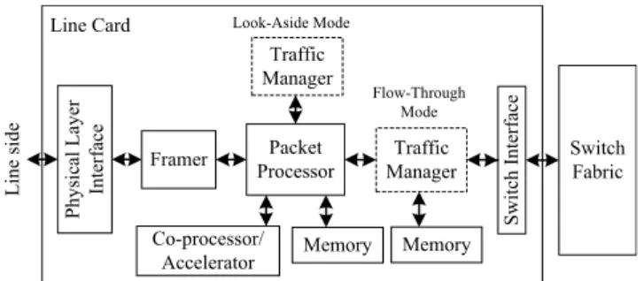
FIGURE 1. Generic architecture around the traffic manager in a line card.
Current solutions use dedicated traffic management inte-grated within NPUs to speed-up traffic processing, with exter-nal memories for packet buffering and queuing purposes. A TM can be found in the data path of a NPU, of a line card, etc. This corresponds to the so-called flow-through mode. By contrast, in the look-aside mode, the TM is outside the data path and it communicates only with the NPU or the packet processor, acting as a co-processor (see Fig. 1). The NPU sends tags, temporary headers, or packet descriptors to the TM. The packet buffer is only attached to the packet processor.
The available traffic management solutions in the liter-ature are essentially commercial products with only few works done in academia. Paulin et al. [25] proposed a mul-tiprocessor system-on-chip (MP-SoC) architecture for traffic management of IPv4 forwarding. The proposed platform is composed of multiple configurable hardware multi-threaded processors, with each processor running part of the traffic management features or tasks. To process more traffic and to cope with network requirements, this architecture requires more processors, eventually limiting its scalability.
Zhang et al. [14] proposed a complete TM implemented in an FPGA platform, focusing on the programmability and scalability of the architecture to address today’s networking requirements. However, the queue management solution that was adopted slows down the entire system with at least 9 cycles per enqueue/dequeue action, and an implementation running at 133 MHz. This TM solution achieved around 8 Gb/s for minimum size 64 byte packets.
Khan et al. [26] proposed a traffic management solution implemented with dedicated circuits that can support 5 Gb/s with full duplex capabilities. Khan showed all the design steps up to the physical realization of a TM circuit. This solution remains rigid as it targets an ASIC. This design choice limits its ability to support future networking needs.
Table 1 summarizes the TM solutions offered by com-mercial vendors and published by academia, along with the platform for which they were developed, their configuration and the reported throughput.
III. TRAFFIC MANAGER ARCHITECTURE
In this section, we present a generic TM architecture and its functionalities in a line card. Then, we detail its underlying modules and some supported packet scheduling schemes.
TABLE 1.Traffic management solutions.
It is of interest to mention that this work is an extension of a previous related work [28], [29], which is extended as follows:
1) Integration of a queue manager (QM) with throughput reaching 100 Gb/s for minimum sized packets, which is a significant improvement over the previously reported 47 Gb/s (More details are given in SectionIII-B.5). 2) Policer functionality with decision based on actual
queue occupancy and flow heuristics to actively assess the flow state and manage any eventual congestions and flow attacks (see SectionIII-B.2).
3) Analysis of TM operations leading to improvements that allowed matching the performance of hand-written register transfer logic (RTL) codes from an HLS design (see SectionV-A).
4) Test and validation on the ZC706 FPGA board of the TM design to verify its correct functionality after placement and routing (More details are given in SectionVI-B).
A. TRAFFIC MANAGER OVERVIEW AND FUNCTIONALITIES Traffic management allows bandwidth management, priori-tizing and regulating the outgoing traffic through the enforce-ment of service level agreeenforce-ments (SLAs). A SLA defines the requirements that a network must meet for a specified customer, some service, or level of service that must be ensured to a subscriber by the service provider. Popular level of service measures include guaranteed bandwidth, end-to-end delay, and jitter.
Traffic management is applied to different types of traffic that have distinct characteristics and requirements to meet. For example, traffic characteristics are the flow rate, flow size, burstiness of the flow, etc. while traffic requirements are the QoS in general. Overall, network operators are targeting to meet all SLAs, to achieve fairness and enforce isolation, while prioritizing the different traffic flows, and to maximize network utilization through traffic management.
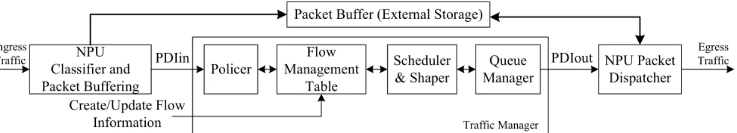
FIGURE 2. Proposed traffic manager architecture.
A generic TM in a line card (switches, routers, etc.) is depicted in Fig.1. The packet processor classifies to a specific flow the data traffic prior entry into the TM. The classi-fied data traffic allows the TM to prioritize and decide how packets should be scheduled, i.e., when packets should be sent to the switch fabric. Traffic scheduling ensures that each port and each class of service (CoS) gets its fair share of bandwidth. Traffic should be shaped before being sent onto the network. The shaper enforces packets to follow a spe-cific network pattern by adding delays. The shaper provides such delays to outgoing traffic to ensure it fits a specific profile (link usage, bandwidth, etc.) and enforces QoS. Packet congestion can cause severe network problems, including throughput degradation, increased delay, and high packet loss rates. Congestion management can improve network conges-tion by intelligently dropping packets. The policer makes decisions to drop packets preventing queues overflow and network congestion.
B. TRAFFIC MANAGER STRUCTURAL DESIGN
The proposed TM architecture is depicted in Fig. 2. It is composed of the following modules: policer, flow manage-ment table (FMT), scheduler, shaper, and a QM. The system architecture assumes that each packet received by the TM has already been tagged with a flow number by the packet processor as per the classification stage. The TM handles only the packet descriptor identifier (PDI). Each PDI contains the priority, packet size, flow ID or number, and its address location in the packet buffer. The PDI may contain other attributes. The size of PDI fields are determined according to the system configuration. For example, to support any standard Internet packet size, the PDI size field is set to 16 bits. The PDI enables packets to be located in the network, providing fast queue management with reduced buffering delays, where the entire packet is stored outside the TM. Usually packet buffering is handled by the NPU. Using the PDI’s has the same impact as if real packets were being handled by the TM, while the actual packet is buffered by the NPU processing engine. With the adopted model, a packet is forwarded to the egress port when its PDI is received by the NPU dispatch unit.
Algorithm 1 illustrates the overall algorithmic operation of the proposed TM. The TM operates in three phases: first, the policer checks if the received PDI is legitimate.
Algorithm 1 Flow-Based Traffic Management Input: PDIin
Output: PDIout
// Phase one: FMT-policer 1: if ( not PDIin.isValid )
2: Drop PDIin and skip to phase three; 3: ref flow ≡ FMT[PDIin.flowID];
4: if ( decision is to drop, from QM_status and flow.Ts ) 5: skip to phase three;
// Phase two: FMT-scheduler/shaper
6: Tag PDIin with flow.Ts and remove validity bit; 7: flow.Ts += PDIin.size × flow.bandwidth-1; 8: Set push to active;
9: Send the new PDI (PDIin) to queue manager; // Phase three: queue manager
10: if ( top PDI in QM is ready to exit or external dequeue activated )
11: Set pop to active;
12: Set QM_action to enqueue, dequeue, replace or no oper-ation according to push and pop states;
13: Check QM_status for packet to be dropped if any;
The policer drops a packet if it is not valid (lines 1-2), or its flow is considered abusive according to its timestamp and the algorithm of Fig.4 (lines 3-5). Second, the scheduler tags each packet with its estimated schedule time (line 6), and asks to push it into the queue (lines 8-9). The shaper computes the schedule time for the next packet of the same flow (line 7). Finally, the queue manager will pop the top packet either if its scheduled time is reached or an external dequeue from the TM is activated (lines 10-11); the push requested by the scheduler and the pop requested by the queue manager are done synchronously (line 12). If the queue status is full with enqueue operation activated in the QM, the last packet in the queue is sent to the drop port (line 13). The traffic manager architecture with its surrounding modules are detailed in the subsequent subsections.
1) FLOW MANAGEMENT TABLE
The TM includes a single FMT in which each record contains state and configuration parameters. The state is a times-tamp (Ts) that is the expected time when the next packet of
the flow can be sent to the egress port, and depends on the packet’s flow. The configuration is the inverse of the allocated bandwidth (Alloc. BW), measured in bit-time, programmable according to required flow restrictions. Fig. 3 depicts the interconnection of the FMT with the different TM modules.
FIGURE 3. General block diagram interconnect of the traffic manager modules.
A single FMT is sufficient, because the priority of packets is implicit to the characteristics of their flow and their band-width usage. The packets are simply ordered according to their scheduled departure times. Note that, contrary to classic TM architectures [13], [15], this TM architecture avoids a hierarchy of queues by leveraging the flow number associated with each packet.
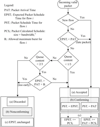
The proposed traffic manager functionalities are shown in Fig.4that presents functionalities related to (a) policing, (b) scheduling, and (c) shaping. These functionalities are further detailed in the next subsections.
2) POLICER
Policing ensures that traffic does not exceed certain bounds. In this work, the policer acts like an arbiter/marker with the following considered control actions, or namely the policing mechanisms:
(i) Drop a packet without enqueue, preventing congestion situations and overflow of the TM queue.
(ii) Drop a packet from the QM while enqueuing.
(iii) Forward incoming traffic if queue capacity allows it, i.e., there is room for the incoming packet.
The policing decision algorithm is a heuristic based on the packet timestamp record from the FMT and queue occupancy status, as depicted in Fig. 4 with TM policing functionality (a).
For the first mechanism (i), the policer acts before the packet is enqueued (so this control mechanism is an active congestion scheme). It checks if the packet is allowed based on the FMT records as stated in Algorithm1(lines 1-2), and to prevent queue overflow (lines 3-5). Once the packet passes the policer, it enters the next stage (scheduler/shaper).
The second mechanism (ii) is activated while the QM status is full, and the incoming packet PDI is legitimate. In that case, the last packet in the queue is dropped to have room to accommodate a legitimate packet as depicted in Algorithm1
in line 13 (so this control mechanism is a passive conges-tion scheme). The third mechanism (iii) reflects the normal
FIGURE 4. The proposed TM functionalities: (a) policing, (b) scheduling, and (c) shaping.
operation of compliant flows entering the TM. It is activated when the first mechanisms (i) and/or (ii) do not apply in a given cycle.
Policer mechanism (iii) enables to absorb bursts by check-ing the queue occupancy in real-time, if enough room exists, the burst is allowed to enter the TM until 1/3 of queue occupancy (first threshold) where packet are virtually green in analogy to three color markers [35]. Above this thresh-old, we start applying the burst limit for each specific flow, up to 2/3 of queue occupancy (second threshold, packets are virtually yellow). Beyond the second threshold, the first policing mechanism (i) is applied more aggressively. Only compliant flows are granted entry according to their expected arrival time (stored Ts records of each flow in the FMT, see Fig. 4). Thus, packets are virtually red and discarded as nonconforming to prevent overuse of the bandwidth and network congestion.
3) SCHEDULER
The proposed TM scheduling functionality is depicted in Fig.4(b). The purpose of scheduling is to tag each PDI prior entry into the QM as depicted in Algorithm1(line 6). This schedule represents the earliest time at which the packet should be sent back to the network. Tagging the incoming packet plays an important role in avoiding that low pri-ority packets be dequeued before the higher pripri-ority ones.
Also, the same holds for older existing packets versus the current incoming ones. This time tag is calculated from the shaping policy (detailed in the next subsection).
4) SHAPER
After the policer stage, each received packet is tagged with a timestamp. Packets timestamps of different flows are com-puted according to Fig. 4 with the TM shaping functional-ity (c). The Ts value stored in the FMT depicts the earliest moment in time that the PDIin has to wait in the QM before it can be dequeued (PST), while the new computed Ts is the expected packet schedule time (EPST) for the upcoming packet for the same flow i. The calculated packet schedule time is in terms of clock cycles, and it depends on the size of the incoming packet and the corresponding inverse allocated bandwidth of flow i, as depicted in Algorithm 1 (line 7). This shaping enables the exact calculation of the EPST of incoming packets belonging to the same flow i, to follow and guarantee the requested flow bandwidth.
The adopted shaping policy enables a fair share of the bandwidth to the different flows, enforcing isolation through prioritization. For non-compliant flows trying to flood the network, their packets timestamps would be de-prioritized with this shaping policy, and therefore they would not affect the compliant one’s as their Ts would be larger, i.e., they would have low priority. Nevertheless, once the upper thresh-old of the policer heuristic is reached (the allowed burst limit), with no room available to absorb this abusive flow in the QM (queue is 2/3 full), policer’s first and second control mechanisms (i, ii) are both activated. Packets belonging to the non-compliant flows will be dropped by the policer. They will be seen as part of a flow attacker or bandwidth abuser, and will not be allowed until the source’s flow reduces its transmission rate, while complying with policer’s first or second control mechanisms.
5) QUEUE MANAGER
The most important component of the QM is the PQ that is responsible for enqueuing, dequeuing and replacing incom-ing packets in a sincom-ingle clock cycle. Also, the PQ sorts the packets in order of priority according to their timestamps in ascending departure order. More details about the queue management can be found in [8] and [9].
Fig. 5 depicts the PQ content. The PQ is divided in m groups. Each group contains N packets Ag, . . . Zg,
FIGURE 5. The hardware priority queue content.
where g is the group number. Ag and Zg represent the min
and max elements, respectively, of that group, and all remain-ing elements are placed in an unordered set Sg. Namely,
a group Xi contains N elements {Ai, Si, Zi} with Si =
{Xi\{min Xi, max Xi}}. The letters A. . . Z are used for
gen-erality, regardless of the actual number of packets, except in examples where N is known. Each group is being con-nected with its adjacent groups, each independently apply-ing in parallel a common operation on its data. This PQ architecture is register-based single-instruction-multiple-data (SIMD), with only local data interconnects, and a short broad-casted instruction.
The priority queue accepts a new entry or returns the packet tag (PDI) with the lowest timestamp every clock cycle. The three basic operations supported by the priority queue are enqueue, dequeue, and replace (i.e., a combina-tion of dequeue-enqueue), while the packet movement obeys Algorithm2 for each defined queue operation representing packet selection and sort inside each distinct queue groups. From the performance analysis of this hardware PQ from [8], the performance decreases in O(log N ), where N is the num-ber of packets in each group, while the quality of dismissed elements when the queue is full is 1/N (lower is better). In this work, N is fixed to 2 packets in each queue group, for all queue sizes. The PDI timestamp at the top of the queue (high-est priority element) is compared to the current system time (in clock cycles). If the PDI Ts is reached, the pop signal is activated (Algorithm1, lines 10-11), and the queued elements are re-ordered according to their schedule time (Algorithm2). Also, an external pop can be issued, for example in case the packet dispatcher is idle. The packet at the top of the PQ is sent to the NPU packet dispatch unit to be dequeued from the
Algorithm 2 Hardware Priority Queue Operations Input: PDIin (Element In)
Output: PDIout (Element Out = A1, but not pertinent on enqueue)
for all groups i (i = 1, 2, . . . m) do // On enqueue operation: group i ← order{Zi−1, Ai, Si};
// On dequeue operation: group i ← order{Si, Zi, Ai+1}; // On replace operation:
group i ← order{max{Zi−1, Ai}, Si, min{Zi, Ai+1}}; Where:
• order X = hmin X, X \{min X, max X}, max X i • S = {X \{min X, max X}}
• Z0is the incoming packet (Element In),
• Am+1is the ‘‘none/invalid’’ packet equivalent to empty cell which must compare as greater (>) to any valid packet,
• max{Z0, A1} = Z0during replace, since A1is dequeued, • From invariants 1 and 2 [8], we have A1≤(S1) ≤ A2≤ (S2) ≤ A3. . . , etc. while the Zi’s are gradually ordered.
packet buffer, and sent back to the network either to an egress port or the switch fabric interface (see Fig.2).
6) PROGRAMMABLE TRAFFIC MANAGER a: NEW FLOW CREATION
To allow creating new flows and erasing the record of inac-tive ones, the Ts in the FMT can be updated in real-time. This feature enables to create new flows in the FMT and override any previous records without requiring FPGA re-synthesis. This is done by updating directly the on-chip Block RAMs (BRAMs) through the create/update port. This latter information is either forwarded from the control plane or the packet processor to the TM through the create/update flow information port. During this phase, the PDIin port should contain all necessary information for flow creation.
b: FLOW BANDWIDTH UPDATE
During operation of the TM, the bandwidth of one or a set of flows can be increased/decreased by the network opera-tor, or as requested by the application requirements, a change in the QoS, or to exploit the unused bandwidth of the inac-tive flows. Updating the inverse allocated bandwidth records can be done simultaneously while processing the incoming traffic, with no performance impact. This is done through the use of dual port memories, enabling a single read and write in the same clock cycle to process and update different incoming flow bandwidth traffic information. During this phase, the create/update flow information port should contain all necessary information for flow update.
c: P4 SUPPORT WITH EXTERN MODULES
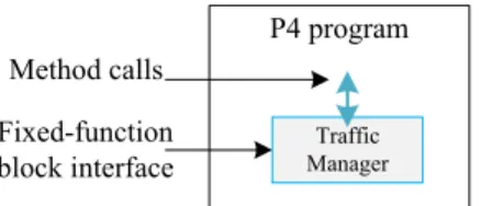
P416 supports integration of specialized hardware through extern. The TM is coded in C++ and can be easily ported into P4 program as an extern object/function, and attached to a flexible and programmable pipeline. The TM can be seen as an external accelerator attached through an extern control interface [39], [40].
In a programmable pipeline, P4 programs can request the operation implemented by the extern object/function (for example the TM) as depicted in Fig.6. The functionality of the TM is not specified in P4, but only the interface is. The interface of the extern object/function can be used to describe the operation it provides, as well as its parameters and return types. This interface is generally exposed to the data plane. It should be noted that the P4 program can store and manip-ulate data pertaining to each packet as user-defined metadata
FIGURE 6. Block diagram representing a P4 program and its extern object/function interface.
directly with the interface to the TM, without using the intrin-sic metadata (control/signals) as defined in the P4 language specification [39].
C. GENERAL PACKET SCHEDULING SCHEMES
Packet scheduling schemes can be categorized in two classes: timestamp-based that achieve good fairness and delay bounds, but that suffer from high computational com-plexity, and round-robin based that are simpler, but that suffer from large delay bounds. Further, another classification is according to the work conserving nature of the scheduler, i.e., the link is never idle whenever a packet remains in the queue. On the other hand, a non-work conserving scheduler will not service a packet even though the link is idle due to a scheduling policy, or whenever the scheduling time is not yet met [35].
Our proposed scheduler is timestamp-based, non-work conserving, as packets will be served only when their sched-ule time is reached (dequeued from QM). To be able to service packets at idle link, an external dequeue from the TM should be issued if the link is idle, to service the top packet in the queue as detailed in SectionIII-B.5.
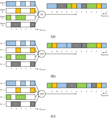
1) EXAMPLES OF SUPPORTED SCHEDULING SCHEMES Our proposed scheduler/shaper can support different existing scheduling schemes like Round-Robin (RR) and Weighted Round-Robin (WRR), while supporting strict priority scheduling by default as the QM is built around a PQ.
Let us consider the examples depicted in Fig. 7a with RR, Fig. 7b with WRR offering bulk service, and Fig. 7c with WRR offering smooth service scheduling schemes.
In RR-based scheduling, each queue is served once during the scheduler iteration or round. This is one of the simplest example of scheduling to implement as timestamps of dif-ferent packets received from each queue are incremented by the number of existing queues. In the example of Fig. 7a, the four-queue system from top to bottom A, B, C, and D, queue A packets would have Ts as 0, 4,. . . etc., 2nd queue B would have Ts as 1, 5, . . . etc., and so forth for each received packet. Hence, to schedule packets according to RR, we should simply initialize the four first Ts flows of our scheduler to 0, 1, 2, 3 and increment the upcoming packets Ts’s by the number of queues (4).
In the same way, WRR can be implemented through proper Ts initialization and weight adjustment, especially for the bulk service. For the example of Fig. 7b, packets are trans-mitted as AABCDD as queues A and D are each served two times over six (33%), while queues B and C are served one time over six (17%). So, we should initialize the four first Ts flows to 0, 2, 3, 4. For the first and fourth flows (queue A and D), the upcoming packets Ts’s increment factor should alternate between 1 then 5, while packets of the second and third flows are incremented by a constant 6. With these increment factors, the scheduler is able to offer the sequence AABCDD. It should be noted that supporting this alternation may require extra logic during implementation for the bulk
FIGURE 7. RR and WRR scheduling schemes. (a) Round-Robin. (b) Weighted Round-Robin: bulk service. (c) Weighted Round-Robin: smooth service.
service scheduler. For fairness reasons, smooth service is desirable with the ABDACD sequence. The latter sequence can be implemented through Ts’s initialization to 0, 1, 4, and 2 while the increment factor is 3 for A and D, it remains 6 for B and C. For the above schedulers, the external dequeue is sufficient with no need to use the system time to issue a dequeue in the QM (see SectionIII-B.5).
One of the most popular scheduling scheme is the weighted fair queuing (WFQ), as it approximates the ideal General-ized Processor Sharing (GPS) scheduler. However, due to its O(n) complexity, where n is the maximum number of nonempty queues, the required calculations at each packet arrival or departure in the WFQ are very expensive. Other packet fair queueing (PFQ) algorithms have been developed in order to reduce this complexity, as detailed in [38]. A good approximation to WFQ is Start-Time Fair Queueing (STFQ). The following shows how we can support this scheduler in a way that differs from [37]. The STFQ requires a virtual start time before a packet is enqueued. The virtual start time is computed as the maximum between the virtual finish time for flow i and the virtual time. The virtual finish time is the timestamp read from the FMT for the packet of flow i in our case, and the virtual time is the last dequeued packet Ts across all flows, that is the last dequeued Ts packet from the QM. So, STFQ requires only an additional comparator for selecting the maximum Ts. This comparator will not impact the per-formance during implementation as the required information is already available from the FMT and QM.
For hierarchical scheduling, we can support hierarchical (H-PFQ) with rate limitation guaranteed, as our QM does not
allow modification of already enqueued packet timestamps upon arrival of future packets. Let us consider the example depicted in Fig.8. If all queues A, B, C, D are nonempty, the service rate is 33% for A, 17 % for B and 25 % for C and D. If queue A is empty or inactive, B would be served 50 % of the time according to the left node bandwidth. In Sivaraman work [37], hierarchical scheduling is done by using a tree of Push-In First-Out (PIFO) queues. However, in our case, with a single queue model, our assigned weights are programmable (through flows bandwidths). So, it only requires updating the flow bandwidth of queue B according to the traffic conditions, as a solution to use the unexploited bandwidth of queue A packets. On the other hand, when the packets of queue A arrive, they can start a bit earlier than the current time of B packets to re-balance the portions of bandwidth usage between A and B.
FIGURE 8. Hierarchical packet fair queueing.
2) DISCUSSION
Sivaraman [37] proposed a programmable packet schedul-ing architecture usschedul-ing Atoms processschedul-ing units representschedul-ing a programmable switch’s instruction set. In Sivaraman work, the scheduling model is composed of two components: 1) a tree of PIFO queues. A PIFO is a PQ that allows elements to be enqueued into an arbitrary position based on the element’s rank, but dequeues elements from the head. 2) the computa-tion of an element’s rank is done before it is enqueued into the PIFO, this computation is called a packet transaction [36].
In comparison to Sivaraman scheduler, our scheduler behave in the same way as to tag each received packet with a timestamp prior entry to the QM. However, in Sivaraman work, the rank computation is done through Atoms process-ing units runnprocess-ing the schedulprocess-ing code. In this work, we tar-get an FPGA platform from which each flow has an initial timestamp and an inverse allocated bandwidth that can be updated at run time. More details about scheduling schemes support can be found in Section 3 of Sivaraman paper [37] as our schedulers are comparable. It should be noted that in this work we focus on traffic management and not specifically on scheduling.
IV. HANDLING TIMESTAMP WRAP AROUND
In general, the range of priority key values used in the PQ is much smaller or comparable to the actual range of stamps
used in the scheduling module. Therefore, priority values may wrap around (overflow). For example, timestamps that handle packet transmission times with 1 GHz rate will wrap around every 4 seconds for 32-bit keys. Having both pre-and post-wrap around timestamps present in the PQ would result in order errors, i.e., post-wrap around timestamps will be regarded as smaller. We propose to mitigate this issue by considering the following solutions.
A. USE OF A WIDER KEY
The configuration of the data type for the timestamp can be changed to a variable length type in the TM code through the arbitrary precision package from Xilinx. A wrap around every year would happen with 55-bit variable length, two years with 56 bits, etc., with the above clocking frequency (1 GHz). With 64-bit priority keys, the wrap around would happen every 585 years. It is a fair assumption that the circuit will not be operated without interruption for a period that long, and 64-bit might even look exaggerated, but this solution is taken as a reference to estimate maximum resource usage and lowest design performance. Wider keys require more storage capacity and wider comparators that eventually impact the critical path of the design.
B. USE OF A 32-BIT KEY
The use of 32 bit key length has the advantage of halving the total length of the Ts in the PDI field. This impacts directly the memory usage in the FMT. Also, the complexity of the hardware used in the QM is reduced, especially the multiplexers and comparators. However, the use of 32-bit key requires adequate recalculation of the flow timestamp records in the FMT, before each wrap around.
This wrap around calculation is done as follows. Prior each system time wrap around, the FMT Ts records are recalculated when the system time exceeds the wrap around threshold (Twa) according to (1), where Bmaxis the maximum
burst threshold of all flows, and # FMT _flows is the total number of flows supported by the FMT.
Twa=(232−1) − (Bmax + # FMT _flows) (1)
Each FMT Ts record exceeding the Twais recalculated by
subtracting from it the current system time, while the other flows Ts’s under the threshold have their records initialized to zero. In the present case, during FMT Ts records recalcula-tion, the incoming PDI’s are stored temporarily inside a buffer (the length of this buffer corresponds to the total number of supported flows in the FMT), to prevent order errors in the QM between already recalculated Ts and the other waiting flows, while the other packets in QM are served normally. The TM resumes its normal operation as soon as all records are recalculated. Assuming a FMT supporting 1024 flows, the TM would take 1024 cycles to recalculate the new times-tamps prior resuming its normal operation after a time wrap around. If the TM is running at 100 MHz, a wrap around would happen every 42 seconds, and during the recalculation phase an incoming PDI has to wait in the temporary buffer
10 µs to be processed in the worst case scenario. Also, the QM should be empty to resume the TM normal operation. V. HLS DESIGN METHODOLOGY AND CONSIDERATIONS In this section, we first present the analysis of operations required by the proposed TM design. Then, we detail the steps we apply in HLS to obtain the desired throughput and latency. A. ANALYSIS OF TRAFFIC MANAGER OPERATIONS
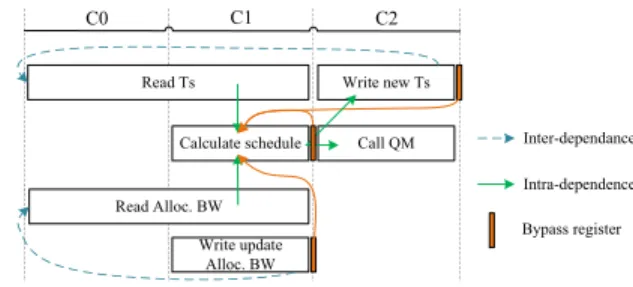
The timing diagram demonstrating correct operation of the proposed TM is shown in Fig.9. The required operations for the TM to process any incoming PDI (representing concise packet information) are to check the FMT record for the spe-cific incoming flow Ts and queue occupancy status, make a decision to drop or forward it, update the FMT flow’s record, and finally send it to the QM with a Ts tag. Therefore, the TM operations consist in reading Ts memory (steps C0-C1), calculating the new schedule time (step C1), and writing it back to the same memory location (step C2). Moreover, a FMT bandwidth (Alloc. BW) access is required with a read and/or write (update) during steps C0-C1. Finally, the PDI is forwarded to the QM according to policer’s decision in step C2. These are the specific tasks done by the proposed TM for each incoming PDI at any given clock cycle. B. DESIGN METHODOLOGY
The HLS process is initiated by specifying the C++ design files, a target FPGA device, and appropriate directives and constraints to apply to the design (that are specific to the HLS tool). The HLS process can be described in three steps:
1) Extraction of data and control paths from the high-level design files.
2) Scheduling and binding of the RTL in the hardware, targeting a specific device library.
3) During the above step, optimizations are dictated by the designer to guide the HLS process, through specific directives and constraints.
From Fig.9, it can be seen that the minimum latency that can be achieved from our design operation is two cycles, with an initiation interval (II) of 1 clock cycle, i.e., every clock cycle an output PDI is ready. Thus, to target this optimal per-formance through HLS, the three directives that we focused on are: 1) a latency directive targeting 2 clock cycles, 2) a pipeline directive targeting an II of 1 cycle, and 3) a memory
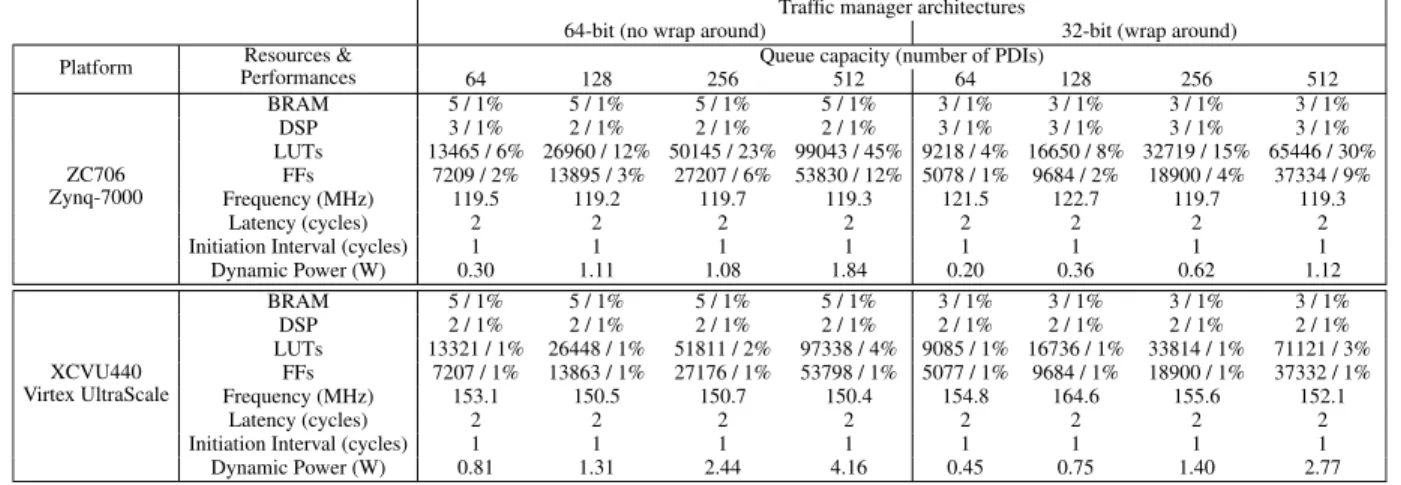
TABLE 2. Resource utilization and achieved performance of the proposed traffic manager with 64 and 32 priority key bits on different platforms.
dependency directive asking for two separate true dual port memories for accessing the Ts and flow bandwidth records in the FMT. As HLS constraint, we target the lowest feasible clock period without violating the desired design latency and II mentioned above. It should be noted that an adequate access memory bypass is required if back-to-back similar PDIs of the same flow are received cycle after cycle, at minimum initiation interval. The reason is that Alloc. BW and Ts are required in the first stage, while they are updated in the sec-ond and third stages of previous PDI (see inter-dependences in Fig. 9). Hence, we designed a two-stage bypass for the Ts memory and one-stage bypass for the flow bandwidth memory, respectively. The achieved implementation results are detailed in SectionVI.
VI. IMPLEMENTATION RESULTS
In this section, we detail the hardware implementation of our proposed TM architecture, resource usage and achieved performance, for different configurations (64-bit and 32-bit priority key with 40-bit metadata). Then, comparisons to existing works in the literature are discussed. Finally, the hardware validation environment is presented.
A. PLACEMENT AND ROUTING RESULTS
The proposed TM was implemented on a Xilinx ZC706 board (based on the xc7z045ffg900-2 FPGA), and a complete design was also produced for a XCVU440 Virtex UltraScale device (xcvu440-flgb2377-3-e FPGA). Resource utilization of the entire TM architecture for different QM capacities was characterized in terms of the number of supported PDIs and the obtained performances. Results are shown in Table2for designs with 64 and 32-bit priorities, N = 2 (the number of PDIs in each group of the queue), and a FMT supporting up to 1024 distinct concurrent active flows. It should be noted that we can support up to 1024 flows in all implementations. Supporting up to 1024 flows is a design decision and is not imposed by a limitation of FPGA BRAM resources. This number of flows was deemed sufficient based on the analysis reported in [14], while flows are identified from the 5-tuple
information. More flows can be supported if that parame-ter is suitably set prior to the design HLS, placement and routing.
In the reported TM implementation, only flip-flops (FFs) and look-up tables (LUTs) were used in the QM module to obtain a fast and pipelined architecture. On-chip memory (Block RAM_18K) is used only in the FMT module. The achieved clock is less than 8.40 ns on the ZC706 platform, for 512 deep queue capacity, with both 64-bit and 32-bit pri-ority TM architectures. When targeting the XCVU440 FPGA, the achieved clock is less than 6.72 ns for both TM architec-tures, with the latter queue capacity. The 32 bit architecture consumes 34% fewer LUTs and 31% fewer FFs than the 64-bit TM architecture, for both the ZC706 platform and XCVU440 FPGA device.
The achieved initiation interval (II) is one PDI per cycle, while the TM throughput is 80 Gb/s for both 64 and 32-bit architectures under the ZC706, for 84 bytes minimum size Ethernet packets (including minimum size packet of 64 bytes, preamble and interpacket gap of 20 bytes). Under the XCVU440 UltraScale FPGA, the achieved TM throughput is 100 Gb/s for both 64 and 32-bit architectures. The design latency is 2 clock cycles, i.e., the TM is fully pipelined and each incoming PDI takes a constant 2-cycle to be processed. It should be noted that accessing a memory location and updating it in the FMT takes at least 2 clock cycles (as explained in SectionV-B and Fig.9) on the target FPGA. This constraint is critical as the core operation consists of a read or read-modify, followed by a write to a memory. While writing the result to the memory, the QM is activated to reduce the design latency, explaining the necessity for 2 clock cycles, which is achieved by HLS with minimum design efforts and more flexibility, enabling faster design space exploration than hand-written RTL designs.
The total dynamic power consumption when targeting the ZC706 is estimated by the Vivado tool at 1.84 and 1.12 W respectively for the 64 and 32-bit architectures, which rep-resents a 39% reduction for the latter. When targeting the XCVU440 UltraScale device, the power usage is reduced by 33% between the TM architectures (see Table 2) for
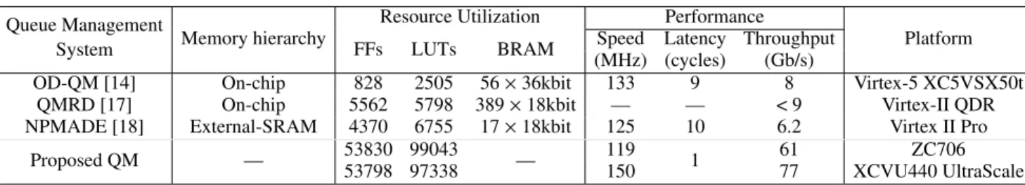
TABLE 3. Memory, speed and throughput comparison with queue management systems.
a 512 queue capacity. The power consumption is dom-inated by the QM array. For example, the 512×104 or 512×72 queue bits for 64 and 32-bit architectures represent 90% of the dynamic power usage, when minimum packets sizes of 64 bytes are received at each cycle (back-to-back). Let us recall that the QM contains a PQ that is a highly parallel regular array of registers and comparators. The total queue capacity that can be supported by the XCVU440 FPGA is around 13.2k PDIs with 64-bit and 18.1k PDIs with 32-bit priority keys. From Table1, comparing the reported results with other traffic management solutions under different plat-forms, the achieved TM performance can be compared to those obtained with design expressed at lower level hardware description languages (HDLs) [14], [15], [19], [22]–[27].
Table 3 summarizes results obtained with various queue management architectures, knowing that the throughput of the QMRD [17] system depends on the protocol data unit (PDU) payload size, the reported OD-QM [13] results are for 512 active queues, and 64 bytes per packet. To make sure that our design is comparable, it was implemented with a total of 512 PDIs queue capacity, 64/32 bit priority, and the worst case egress port throughput is reported assuming 64-byte packets, supporting pipelined enqueue, dequeue and replace operations in a single clock cycle, i.e., O(1).
Compared to existing NPU solutions like Broadcom [19], and Mellanox NPS-400 [22], that can support up to 200 and 400 Gb/s respectively with built-in queue management sys-tems, our proposed TM architecture is scalable in terms of performance for different queue capacities. Using the single FPGA on a ZC706, we can support two 40 Gb/s links assuming minimum 64 byte sized packets, while with XCVU440 UltraScale, we can support four 100 Gb/s links with a QM that could reach 4.5k PDIs capacity per link. To scale up to 400 Gb/s with ZC706 boards, we can use several FPGAs in parallel like in a multicard ‘‘pizza box’’ system. Moreover, it should be noted that an FPGA is much more flexible than a fixed and rigid ASIC chip.
B. HARDWARE VALIDATION ENVIRONMENT
To verify the correct functionality of the proposed TM after FPGA placement and routing, we tested the proposed 64-bit architecture on a Zynq-7000 ZC706 FPGA board from Xilinx. Fig. 10depicts the organization of the testing plat-form, it consists of four parts: the host computer user inter-face, known as the Xilinx Software Development Kit (SDK) tool, the processing system (PS-side), the PS-PL interconnect (AXI-bus), and the programmable logic (PL-side).
1) HOST COMPUTER USER INTERFACE
The user interface manages the data to display on-screen. This data is normally requested by a user from the PL-side. It represents the outputs (valid and dropped PDIs) from the TM at a given cycle. This data is read from the storage buffer on the FPGA board through a C program that runs on the PS-side. It is transferred to the processing system through a built-in UART and handled by the SDK.
FIGURE 10. The TM hardware validation environment.
2) PROCESSING SYSTEM
The ZC706 board integrates a dual-core ARM. The ARM processor is clocked at 667 MHz and runs a native operating system. The main objective of the PS-side is to ease the process of data exchange between the user and the PL-side through the PS-PL interconnect, i.e., by the built-in AXI-bus. The ARM is used to manage data transfers from the FPGA part to the user interface.
3) PS-PL INTERCONNECT
Communication between the PS-side and the PL-side is done using AXI-bus interface. For testing, we used the AXI-Lite bus interface known to offer low-throughput and low-latency communication capabilities [32]. It allows transferring the generated data obtained from the TM to the PS side. A slow bus solution is sufficient in this case as data is requested from the output buffers with one PDI each time.
4) PROGRAMMABLE LOGIC
We use the available logic resources in the FPGA chip to implement the TM architecture. The TM can accept a PDI every clock cycle, and can produce an output PDI in the same
cycle. Transmitting such data flow to the host computer is impractical. One solution is to store the output PDIs from the TM in an output buffer, and then request them one by one later. The generated PDIs are known a priori, and they are displayed through the user interface. This allows analyzing specific characteristics of the design under test. For example, reports that could be generated can relate to back-to-back ingress burst handling, flow bandwidth abuse and policer dropping capability, over-exceeding the ingress port limit TM behavior, etc. These tests confirmed the correct functionality of the proposed TM and matched the co-simulation results that were detailed in [29, Sec. IV].
C. FUTURE WORK AND RESEARCH DIRECTIONS
Statistics gathering is one of the complex operation to per-form as it lays in the critical path of packet processing of any network device. During development of the proposed traffic manager, statistics gathering for different flows was designed in a separate module external to the traffic manager with no interaction. This was chosen to avoid degrading the performance of the traffic manager, and have flow statis-tics reported once per second. Statisstatis-tics gathering could be integrated in the traffic manager. Alternatively, we could use dedicated metadata field for reporting flow state per received packet. This enables to have information about network flows in a cycle accurate manner, i.e., it can allow in-band network telemetry [41].
Another future research direction is to integrate the clas-sification stage within traffic management. This could lead to faster creation/update of flow information from the con-trol plane, classification and traffic manager stages. Also, it could facilitate the control, management and synchroniza-tion between different network equipment modules.
A recent trend in the literature led by the P4 language consortium is to integrate the traffic management in the programmable data plane [42]. In today’s P4 programmable switches, traffic management is not supported directly in the data plane. An effort and thrust toward programmable traffic manager functionalities in today’s network data plane is a near future target. This would be interesting to have a complete view of the system from classification, traffic management and packet buffering that are all programmable while user custom in-line processing would be supported by the P4 language directly in the network data plane.
VII. CONCLUSION
In this work, we proposed, implemented and evaluated a high-speed, low-latency, programmable and scalable traffic manager architecture intended for flow-based networking. It is capable of providing all the functionality of typical network traffic managers from policing, scheduling, shaping and queuing. The proposed traffic manager architecture is coded in C++ providing more flexibility, and easier imple-mentation than the reported works in the literature that were coded in VHDL, Verilog, etc. It is of interest to mention that the queue manager supports 64 or 32 bit priority keys with
40-bit of metadata representing the size, flow ID, and packet address, while the concise packet information tag is up to 104-bit.
The proposed traffic manager architecture was prototyped in FPGA using HLS and implemented with Vivado from Xilinx, targeting the ZC706 board and XCVU440 UltraScale device. The resulting design is capable of handling high speed network and links operating up to 100 Gb/s with minimum size Ethernet packets. Also, the flexibility of the architecture and the adopted high-level coding style facilitate introduc-ing modifications and enhancements. For example, addintroduc-ing a congestion control mechanism like weighted random early detection (WRED) or using different types of queue in the queue manager, like binary heap, would be straightforward. ACKNOWLEDGMENTS
The authors would like to thank N. Bélanger, researcher at Polytechnique Montréal, for his suggestions and technical guidance. Also, the authors would like to thank J. S. da Silva and the anonymous reviewers for their valuable and enriching comments.
REFERENCES
[1] A. Gupta and E. R. K. Jha, ‘‘A survey of 5G network: Architecture and emerging technologies,’’ IEEE Access, vol. 3, pp. 1206–1232, Jul. 2015. [2] N. Panwar, S. Sharma, and A. K. Singh, ‘‘A survey on 5G: The next
generation of mobile communication,’’ Phys. Commun., vol. 18, pp. 64–84, Mar. 2016.
[3] M. Yu, J. Rexford, M. J. Freedman, and J. Wang, ‘‘Scalable flow-based networking with DIFANE,’’ ACM SIGCOMM Comput. Commun. Rev., vol. 41, no. 4, pp. 351–362, 2011.
[4] S.-W. Moon, J. Rexford, and K. G. Shin, ‘‘Scalable hardware priority queue architectures for high-speed packet switches,’’ IEEE Trans.
Com-put., vol. 49, no. 11, pp. 1215–1227, Nov. 2000.
[5] M. Huang, K. Lim, and J. Cong, ‘‘A scalable, high-performance cus-tomized priority queue,’’ in Proc. IEEE 24th Int. Conf. Field Program.
Logic Appl. (FPL), Sep. 2014, pp. 1–4.
[6] Y. Afek, A. Bremler-Barr, and L. Schiff, ‘‘Recursive design of hardware priority queues,’’ Comput. Netw., vol. 66, pp. 52–67, Jun. 2014. [7] X. Zhuang and S. Pande, ‘‘A scalable priority queue architecture for
high speed network processing,’’ in Proc. 25th IEEE Int. Conf. Comput.
Commun. (INFOCOM), Apr. 2006, pp. 1–12.
[8] I. Benacer, F.-R. Boyer, and Y. Savaria, ‘‘A fast, single-instruction– multiple-data, scalable priority queue,’’ IEEE Trans. Very Large Scale
Integr. (VLSI) Syst., vol. 26, no. 10, pp. 1939–1952, Jun. 2018.
[9] I. Benacer, F.-R. Boyer, N. Bélanger, and Y. Savaria, ‘‘A fast systolic priority queue architecture for a flow-based traffic manager,’’ in Proc. 14th
IEEE Int. New Circuits Syst. Conf. (NEWCAS), Jun. 2016, pp. 1–4. [10] H. W. Poole, L. Lambert, C. Woodford, and C. J. Moschovitis, Eds.
The Internet: A Historical Encyclopedia, vol. 2. Santa Barbara, CA, USA: Abc-Clio Inc., 2005.
[11] A. Lara, A. Kolasani, and B. Ramamurthy, ‘‘Network innovation using OpenFlow: A survey,’’ IEEE Commun. Surveys Tuts., vol. 16, no. 1, pp. 493–512, 1st Quart., 2014.
[12] N. Bastin and R. McGeer, ‘‘Programmable, Controllable Networks,’’ in
The GENI Book, R. McGeer, M. Berman, C. Elliott, and R. Ricci, Eds. Cham, Switzerland: Springer, 2016, pp. 149–178.
[13] S. O’Neil, R. F. Woods, A. J. Marshall, and Q. Zhang, ‘‘A scalable and programmable modular traffic manager architecture,’’ ACM Trans.
Recon-figurable Technol. Syst., vol. 4, no. 2, p. 14, 2011.
[14] Q. Zhang, R. Woods, and A. Marshall, ‘‘An on-demand queue man-agement architecture for a programmable traffic manager,’’ IEEE Trans.
Very Large Scale Integr. (VLSI) Syst., vol. 20, no. 10, pp. 1849–1862, Oct. 2012.
[15] ‘‘Enabling quality of service with customizable traffic managers,’’ Altera Corp., San Jose, CA, USA, White Paper WP-STXIITRFC-1.0, 2005.
[16] F. M. Chiussi et al., ‘‘A family of ASIC devices for next generation dis-tributed packet switches with QoS support for IP and ATM,’’ in Proc. IEEE
Hot Interconnects, Stanford, CA, USA, vol. 9, Aug. 2001, pp. 145–149. [17] R. Krishnamurthy, S. Yalamanchili, K. Schwan, and R. West,
‘‘Share-Streams: A scalable architecture and hardware support for high-speed QoS packet schedulers,’’ in Proc. 12th Annu. IEEE Symp. Field-Program.
Custom Comput. Mach., Apr. 2004, pp. 115–124.
[18] K. McLaughlin, D. Burns, C. Toal, C. McKillen, and S. Sezer, ‘‘Fully hardware based WFQ architecture for high-speed QoS packet scheduling,’’
Integr., VLSI J., vol. 45, no. 1, pp. 99–109, 2012.
[19] 200G Integrated Packet Processor, Traffic Manager, and Fabric Interface
Single-Chip Device, document BCM88650, Broadcom, 2012.
[20] F. Fereydouni and A. M. Otmane, ‘‘A new 10 Gbps traffic management algorithm for high-speed networks,’’ in Proc. IEEE Int. Symp. Circuits Syst.
(ISCAS), New Orleans, LA, USA, May 2007, pp. 2510–2513.
[21] S. Stanley, ‘‘Traffic manager update,’’ Light Reading Report, 2004. Accessed: Jan. 2018. [Online]. Available: Online Available: https://www. lightreading.com/comms-chips/traffic-managers-update/d/d-id/602877 [22] NPS-400 400 Gbps NPU for Smart Networks, EZchip, San Jose, CA, USA,
2015.
[23] 10G Network Processor Chip Set (APP750NP and APP750TM), Agere Syst., Allentown, PA, USA, 2002.
[24] N. Possley, ‘‘Traffic management in Xilinx FPGAs,’’ Xilinx, San Jose, CA, USA, White Paper WP244, 2006.
[25] P. G. Paulin et al., ‘‘Parallel programming models for a multiprocessor SoC platform applied to networking and multimedia,’’ IEEE Trans. Very Large
Scale Integr. (VLSI) Syst., vol. 14, no. 7, pp. 667–680, Jul. 2006. [26] A. Khan et al., ‘‘Design and development of the first single-chip
full-duplex OC48 traffic manager and ATM SAR SoC,’’ in Proc. IEEE Conf.
Custom Integr. Circuits, Sep. 2003, pp. 35–38.
[27] B. Alleyne, ‘‘Chesapeake: A 50 Gbps network processor and traffic man-ager,’’ in Proc. IEEE Hot Chips 19 Symp. (HCS), Stanford, CA, USA, Aug. 2007, pp. 1–10.
[28] I. Benacer, F.-R. Boyer, and Y. Savaria, ‘‘A high-speed traffic manager architecture for flow-based networking,’’ in Proc. 15th IEEE Int. New
Circuits Syst. Conf. (NEWCAS), Jun. 2017, pp. 161–164.
[29] I. Benacer, F.-R. Boyer, and Y. Savaria, ‘‘Design of a low latency 40 Gb/s flow-based traffic manager using high-level synthesis,’’ in Proc. IEEE Int.
Symp. Circuits Syst. (ISCAS), May 2018, pp. 1–5.
[30] H. Fallside, ‘‘Queue manager reference design,’’ Xilinx Inc., San Jose, CA, USA, Appl. Note 511, 2007.
[31] A. Nikologiannis, I. Papaefstathiou, G. Kornaros, and C. Kachris, ‘‘An FPGA-based queue management system for high speed network-ing devices,’’ Microprocess. Microsyst., vol. 28, nos. 5–6, pp. 223–236, Aug. 2004.
[32] Vivado Design Suite AXI Reference Guide, v4.0, document UG1037, Xilinx, 2017.
[33] Barefoot. The World’s Fastest & Most Programmable Networks. Accessed: Aug. 2018. [Online]. Available: https://www.barefootnetworks. com/resources/worlds-fastest-most-programmable-networks/
[34] P. Bosshart et al., ‘‘P4: Programming protocol-independent packet proces-sors,’’ ACM SIGCOMM Comput. Commun. Rev., vol. 44, no. 3, pp. 87–95, Jul. 2014.
[35] R. Giladi, Network Processors: Architecture, Programming, and
Imple-mentation (Series in Systems on Silicon). San Mateo, CA, USA: Morgan Kaufmann, 2008.
[36] A. Sivaraman et al., ‘‘Packet transactions: High-level programming for line-rate switches,’’ in Proc. SIGCOMM, 2016, pp. 15–28.
[37] A. Sivaraman et al., ‘‘Programmable packet scheduling at line rate,’’ in
Proc. SIGCOMM, 2016, pp. 44–57.
[38] J. C. R. Bennett and H. Zhang, ‘‘Hierarchical packet fair queueing algo-rithms,’’ IEEE/ACM Trans. Netw., vol. 5, no. 5, pp. 675–689, Oct. 1997. [39] P4 Language Specification, Version 1.1.0, P4.Org, P4 Language
Consor-tium, 2018. Accessed: Aug. 2018. [Online]. Available: https://p4.org/ specs/
[40] J. S. da Silva, F.-R. Boyer, L. Chiquette, and J. M. P. Langlois, ‘‘Extern objects in P4: An ROHC header compression scheme case study,’’ in Proc.
4th IEEE Conf. Netw. Softwarization Workshops (NetSoft), Montréal, QC, Canada, Jun. 2018, pp. 517–522.
[41] R. Mari, ‘‘In-band network telemetry—A powerful analytics framework for your data center,’’ OCP Summit, Mar. 2018. [Online]. Available: https://www.opencompute.org/files/INT-In-Band-Network-Telemetry-A-Powerful-Analytics-Framework-for-your-Data-Center-OCP-Final3.pdf
[42] G. Brebner, ‘‘Extending the range of P4 programmability,’’ P4EU Keynote, Cambridge, U.K., 2018. [Online]. Available: https://p4.org/assets/P4WE_ 2018/Gordon_Brebner.pdf
IMAD BENACER received the B.E. degree in elec-trical and electronic engineering from Boumerdès University, Boumerdès, Algeria, in 2012, and the M.E. degree in electrical engineering from École Militaire Polytechnique, Algiers, Algeria, in 2014. He is currently pursuing the Ph.D. degree with Polytechnique Montréal, Montréal, QC, Canada.
His current research interests include the embedded implementation of image and video processing algorithms, network communication systems, and high-level synthesis targeting FPGA designs and implemen-tations.
FRAN ¸COIS-RAYMOND BOYER received the B.Sc. and Ph.D. degrees in computer science from the Université de Montréal, Montréal, QC, Canada, in 1996 and 2001, respectively.
Since 2001, he has been with Polytechnique Montréal, Montréal, where he is currently a Pro-fessor with the Department of Computer and Soft-ware Engineering. He has authored or co-authored over 30 conference and journal papers. His current research interests include microelectronics, perfor-mance optimization, parallelizing compilers, digital audio, and body motion capture.
Dr. Boyer is a member of the Regroupement Stratégique en Microélec-tronique du Québec, the Groupe de Recherche en MicroélecMicroélec-tronique et Microsystèmes, and the Observatoire Interdisciplinaire de Création et de Recherche en Musique.
YVON SAVARIA (S’77–M’86–SM’97–F’08) received the B.Ing. and M.Sc.A. degrees in elec-trical engineering from Polytechnique Montréal, Montréal, QC, Canada, in 1980 and 1982, respec-tively, and the Ph.D. degree in electrical engineer-ing from McGill University, Montréal, in 1985.
He has been a Consultant or was sponsored for carrying research by Bombardier, CNRC, Design Workshop, DREO, Ericsson, Genesis, Gennum, Huawei, Hyperchip, ISR, Kaloom, LTRIM, Miranda, MiroTech, Nortel, Octasic, PMC-Sierra, Technocap, Thales, Tundra, and VXP. Since 1985, he has been with Polytechnique Montréal, where he is currently a Professor with the Department of Electrical Engineering. He has carried out work in several areas related to microelec-tronic circuits and microsystems, such as testing, verification, validation, clocking methods, defect and fault tolerance, the effects of radiation on electronics, high-speed interconnects and circuit design techniques, CAD methods, reconfigurable computing and applications of microelectronics to telecommunications, aerospace, image processing, video processing, radar signal processing, and digital signal processing acceleration. He has authored or co-authored 145 journal papers and 450 conference papers, and holds 16 patents, and was a Thesis Advisor of 160 graduate students who completed their studies. He is currently involved in several projects that relate to aircraft embedded systems, radiation effects on electronics, asynchronous circuits design and test, green IT, wireless sensor networks, virtual networks, computational efficiency, and application specific architecture design.
Dr. Savaria is a member of the Regroupement Stratégique en Microélec-tronique du Québec and the Ordre des Ingénieurs du Québec, and has been a member of the CMC Microsystems Board, since 1999, and was the Chairman of the CMC Microsystems Board, from 2008 to 2010. He was a recipient of the 2001 Tier 1 Canada Research Chair on the design and architectures of advanced microelectronic systems that he held, until 2015, and the 2006 Synergy Award of the Natural Sciences and Engineering Research Council of Canada. He was a Program Co-Chairman of ASAP 2006 and a General Co-Chair of ASAP 2007.

![[PDF] Tour d'horizon de PhotoFiltre 6.3 | Formation Informatique](data:image/gif;base64,R0lGODlhAQABAIAAAP///wAAACH5BAEAAAAALAAAAAABAAEAAAICRAEAOw==)