HAL Id: hal-03199051
https://hal-mines-paristech.archives-ouvertes.fr/hal-03199051
Preprint submitted on 15 Apr 2021
HAL is a multi-disciplinary open access
archive for the deposit and dissemination of
sci-entific research documents, whether they are
pub-lished or not. The documents may come from
teaching and research institutions in France or
abroad, or from public or private research centers.
L’archive ouverte pluridisciplinaire HAL, est
destinée au dépôt et à la diffusion de documents
scientifiques de niveau recherche, publiés ou non,
émanant des établissements d’enseignement et de
recherche français ou étrangers, des laboratoires
publics ou privés.
Investigation of agglomerated ceramic powders suitable
for cold spray
Geoffrey Celeste, Vincent Guipont, Djamel Missoum-Benziane
To cite this version:
Geoffrey Celeste, Vincent Guipont, Djamel Missoum-Benziane. Investigation of agglomerated ceramic
powders suitable for cold spray. 2021. �hal-03199051�
Investigation of agglomerated ceramic powders suitable for cold spray
Geoffrey CELESTE*, Vincent GUIPONT, Djamel MISSOUM-BENZIANE
Centre des matériaux - CMAT, MINES ParisTech - PSL, UMR CNRS 7633 63 - 65 rue Henri-Auguste Desbruères, 91000 EVRY, France
* geoffrey.celeste@mines-paristech.fr
Abstract
Cold gas spraying is a solid-state deposition process developed for metallic powders as feedstock materials. For ceramic materials, such low temperature-high velocity kinetic process is still questionable but could have interesting advantages. In the CERASOL project (ANR-19-CE08-0009), the nature and the architecture of porous ceramic powders involving agglomerated sub-micrometric grains are investigated. To that purpose, three oxide ceramics powders (alumina, zirconia and yttria) have been prepared for cold spray. These powders were analyzed in order to assess their architecture (composition, particle size, porosity, density, crystallite sizes…). Preliminary cold spray experiments were carried out implementing velocities measurements for various stand-off distances and spraying of coupons with line experiments. The characteristics of the deposited layers have been examined by SEM and XRD in order to discuss the role of the powder architecture on the impact behavior of the nanostructured agglomerated particles. The role of the gas stream that affects the kinetic and the trajectory of the particles is also discussed.
Introduction
The cold spray (CS) is a solid-state deposition process based on severe plastic deformation of the powder feedstock. It is well established that ductile metallic materials can be deposited by cold spray for coating solutions, repairing or manufacturing applications [1], [2]. With this spraying process, rather fine powders (15-50 µm) are accelerated by a supersonic gas stream at a temperature lower than the melting temperature of the material. CS is used to create dense metallic coatings. The mains advantages are also the limitation of heat-induced oxidation and phase transformation, thermal stress, and other common problems encountered in traditional thermal spray processes. A wide range of ductile materials have been effectively sprayed by CS, using different spraying facilities involving high pressure and temperature gas conditions. As-sprayed or heat-treated coatings can exhibit superior mechanical or electrical properties for example [3], [4]. For brittle ceramics, such “cold” deposition process is still questionable but it was found that rather thick and adhesive coatings could be obtained with specific ceramic powders deposited on metallic, ceramic or polymeric substrates: e.g. hydroxyapatite (HA) [5]–[7], TiO2 [8]–[10] Y203 [11] or SiC
[12]. Dense ceramic powder are not relevant because the breaking of the particles leads to blocky fragments staying embedded like grit residues in a sand blasted surface . Recent works on ceramics by CS are mainly devoted to agglomerated ceramic powders that could be more suitable for cold spray
deposition. The impact behavior of porous agglomerated granules that can adhere with possible beneficial compaction of the porous particle has been evidenced in case of HA or TiO2 powders with nano-sized grains leading to successful
build-up of a coating up [13], [14]. The powder could be specifically prepared like for TiO2 anatase powder with a
tailored hydrothermal synthesis [15]. Moreover, powder post-treatment like calcination has been also studied in case of TiO2
powder showing a significant role on the resulting a coating build up [16]. The nature and the surface morphology of the substrate could also influence drastically the impact behavior and the mechanical anchoring of the ceramic powder [17]. For a similar solid-state kinetic spraying of ceramics, known as Aerosol Deposition (AD) process, Akedo introduced The concept of Room Temperature Impact Consolidation (RTIC) [18] and Park defends a shock-induced plasticity and fragmentation phenomena [19] In AD, the impact behavior concerns isolated ultra-fine particles powders previously dispersed in a pressurized gas and further accelerated in a vacuum chamber though a supersonic nozzle. Sufficiently sized particles (200nm – 5µm) undergo the RTIC mechanism during impact by fracturing and plastic deformation and therefore adhere. For smaller particles, an elastic bounding is observed and for larger ones, there is no sufficient coating [20]. For the cold spray of ceramics, the challenge is to promote the high-velocity impact of such ultra-fine particles when agglomerated in micrometric and porous granules. Therefore, it is claimed that the role of the porous architecture of the ceramic granules involving both nano-sized and micro-sized features shall be predominant to control the impact mechanism and the deposition process.
The present work aims at exploring the CS of various agglomerated ceramic powders in order to investigate the role of the nature of the material and those of the architecture of the granules. The purpose is to assess different agglomerated particles that could vary with toughness, hardness, size, porosity and internal cohesion. It is also aimed to have agglomerates having aggregates with different crystallites sizes in the nano-metric range. Al2O3, ZrO2-Y2O3 (3%) and Y2O3
oxide ceramics has been selected because a solid-state deposition process might be of great interested to prevent allotropic or eutectic transformation or amorphization that always occur when thermally sprayed. It could also open new processing routes for functional ceramic coatings that could be doped with thermo-sensitive species.
In this work, six different powders were prepared and analyzed in order to assess their architecture (composition, particle size, porosity, density, crystallite sizes…). Preliminary CS experiments were also carried out implementing velocities measurements and spraying of coupons with line experiments.
Materials and Methods
Ceramic feedstock powders
Al2O3, ZrO2-3Y2O3 and Y2O3 agglomerated powders were
produced with precursors obtained by wet chemical precipitation (Nanoé, Ballainvilliers, France). After drying, precipitates are dispersed in a liquid suspension. Subsequent atomization of the suspensions was carried out by spray drying. Batches of atomized powders were further sieved to enable a small range (mean diameter <20µm) or a medium range (mean diameter <40µm) of granules size. Three batches of as-atomized alumina, zirconia and yttria powders with large or small particles have been selected for this study. Two additional alumina batches were prepared by calcination at 800°c and 1000° C respectively. In case of ytrria, a second batch was also atomized with PVA (PolyVinyl Alcohol) addition. The six different types of agglomerated ceramic powders selected for this paper are summarized in Table 1.
Powders Batches
Al2O3 #1:Medium, as atomized
#2:Small, calcinated 800°C #3:Medium, calcinated 1000°C ZrO2 -Y2O3 #4:Medium, as atomized
Y2O3 #5: Medium, as-atomized
#6: Medium, with PVA binder agent
Table 1: Selected agglomerated ceramic powders Spraying experiments:
Substrates and CS equipements: Aluminum alloy A2017 substrates with (30mm×30mm×3mm) dimensions were grit-blasted with alumina 300µm prior to spraying (Ra: 4.5µm). Two CGS systems has been used for spraying experiments: Low Pressure Cold Spray (LPCS) D523 with air gas available up to 600°C/0.6MPa (Dycomet Europe, The Netherlands) and High Pressure Cold Spray (HPCS) KINETICS3000 (Oerlikon Metco, Switzerland) with nitrogen gas available up to 600°C/3.0MPa. HPCS system has an axial upstream injection while LPCS system has a radial injection in the downstream part of the convergent/divergent nozzle.
Velocity measurements: Mapping of particles velocities distribution were carried out with a DPV-2000 system (Tecnar, Canada) on alumina and zirconia powders invoving the two CS system for various CS gas parameters and spraying distances (without substrate). A rather low range for gas pressure and temperature and a long spraying distances up to 160mm were preferred according previous work on hydroxyapatite powders by CS [5]. A high power diode laser system, CPS-2000, is used to illuminate the in-flight particles moving in front the for DPV-2000 sensor head. Particle velocity maps are drawn in the perpendicular direction of the jet with a scanned surface of 16×8mm² involving 128 measures with steps of 2 mm.. From raw histograms (X,Y, Vpartciles), a Python script is implemented with the plt.countour
function to fit iso-value countour maps. The different
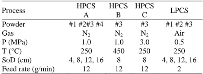
parameters for particles velocities analyses are summarized in the Table 2. Process HPCS A HPCS B HPCS C LPCS Powder #1 #2#3 #4 #3 #3 #1 #2 #3 Gas N2 N2 N2 Air P (MPa) 1.0 1.0 3.0 0.5 T (°C) 250 450 250 250 SoD (cm) 4, 8, 12, 16 8 8 4, 8, 12, 16
Feed rate (g/min) 12 12 12 2
Table 2: Spraying parameters for velocity measurements and line experiments (only HPCS)
Samples spraying: Spraying experiments were carried out only for alumina and zirconia powders #1 to #4 with HPCS system according spraying parameters in Table 2. The purpose was to evaluate both the impact and build-up behaviors of agglomerated powders. Therefore, line experiments with only one pass of the gun moving at 10 mm/s were implemented to observe the resulting materials deposited onto the grit-blasted substrate.
Observations and analyses:
The flowability of the different batches of powders were also assessed by the Hall Flow method and their humidity rate was
also measured with humidity scale at 80°C.
Thermogravimetric analyses (Setaram, Mougins - Sophia Antipolis, France) were implemented out to complement the humidity tests. Specific surface area of each powders was measured by BET with nitrogen adsorbate (ASAP2000, Micromeritics,USA) . The volumetric mass density of the agglomerates was measured by helium pycnometry (AccuPyc II 1340, Micromeritics, USA). X-ray diffraction (XRD) profiles for phase composition analysis were collected on powders and coatings using a D8 Discover (Bruker, USA) with Cu-Kα radiation and a 0–140° 2θ range. The crystallite size of each powder was estimated after the whole pattern decomposition by the Le Bail method (Diffrac.Topas software, Bruker, USA).
Mean particle size of each batch of powder was measured by image analysis applied on optical images of free powders using Stream software (Olympus, Tokyo, Japan). Further views of the powders (free or cross-sectioned after resin mounting and polishing) and of the deposits (top views) were recorded by scanning electron microscope (Nova NanoSEM 450, FEI, USA) using backscattered electron (BSE) mode. Crushed powders were also imaged by transmission electron microscope (Tecnaï 20F, FEI, USA) to observe the agglomerates of grains.
Vickers microhardness of powders was measured on polished cross-section of resin mounted powders (AZ50-4 PRESI, France) with a 0.01kgf/mm2 loading force. 20 indentations on particles were made for each measurement, obtaining indents ranging from 17 to 28 µm. For such indentation test, we ascertained that indent size was at least two times smaller than the cross-section diameter.
Results and Discussions
Powders characterizations
Powders architecture: The typical features are summarized for as atomized powders on Figure 1 to Figure 3.
Figure 1: Al2O3, medium, as atomized (#1)
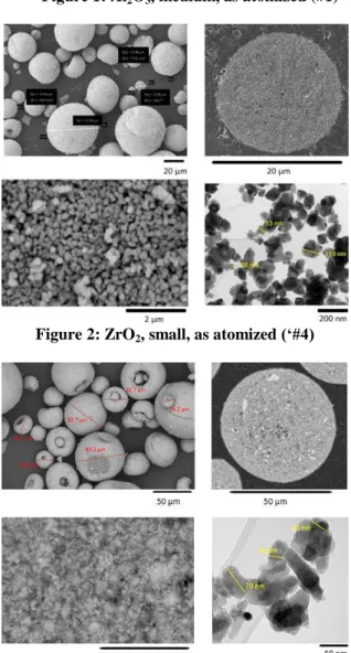
Figure 2: ZrO2, small, as atomized (‘#4)
Figure 3: Y2O3, medium, as-atomized (#5)
From these figures, it can be observed that the three ceramic powders exhibit granules having a spherical shape and a smooth surface due to the ultra-fine size of the agglomerated grains. However, numerous granules have a “donut” morphology which is induced by drying instabilities during atomization. Such defects are not of major concern for a sintering process but shall be probably better controlled for a spraying process. These characteristics were not significantly modified after calcination in case of alumina or if PVA was added before spray drying. Cross-sectioned particles at low and high magnification show the homogeneity and the high compactness of the agglomerated structure of both alumina and zirconia powders (Figure 1, Figure 2). Some micro/nano-pores are present but are difficult to evaluate by image analysis and conventional metallography. In case of yttria powder (Figure 3), it is obvious that there is a mix of fine and coarse agglomerates combined to small and large pores in the micrometric range. Some dimensions of typical grains sizes have been made on the images obtained by TEM. Differentiation of grains and crystallites is difficult at the magnification as they may overlap or interlock. For the alumina (Figure 1), two typical morphologies of the grains can be seen. The first one corresponds to aggregates of wavy contours, irregular contrast, enclosing nanopores and composed of transition alumina nano-grains. The second one corresponds to grains with faceted edges, regular diffraction contrast. They correspond to a single crystal of alpha-alumina, obtained by transformation from a transition alumina aggregate. The larger pores are explained by the difference in density of the transition alumina and alpha alumina. For zirconia (Figure 2) and yttria (Figure 3), the morphologies are similar except about the presence of nanopores.
Powders analyses: The six different powders were analyzed in order to investigate structural, physico-chemical and mechanical properties of the feedstock. The powders characteristics are summarized in Table 3.
Batch number Powder type #1 Al2O3 #2 +800°C #3 +1000°C #4 Zr02 #5 Y2O3 #6 +PVA Mean diam., µm 40 18 36 18 36 33 Humidity rate, % 0.46 0.29 0.23 0.44 0.39 0.49
Hall Flow., s/25g 50 Poor 55 Poor 61 66
Density , g/cm3 3.76 3.86 3.89 5.62 4.48 4.35
/theoretical, % 94.3 96.9 97.6 94.2 89.4 86.8
Surf. area, m2/g 12.5 12.3 7.9 15.3 19.8 18.9
Crystal. size, nm 96 117 146 76 51 51
Hv0.1 57±9 56±10 65±12 39±4 39±5 36±3
Table 3: Powders characteristics
Phase compositions of the various powders were analyzed by
XRD. The as-atomized alumina powder (#1) was
predominantly α-Al2O3 with a 98.3% mass content and some
residual Al(OH)3 as synthesis by-product. After calcination at
800°C or 1000°C, powders #2 and #3 were fully crystallized in α-Al2O3. The as-atomized zirconia powder #4 with yttria
addition (3% mol.) was 43.0% tetragonal (t-ZrO2) and 57.0%
PVA binder agent) were cubic (c-Y2O3). PVA was not
detected by XRD but a 7.6% mass content was determined by TGA analysis.
Powders with a medium diameter 33-40µm were selected for two batches of each alumina powders (#1 and #3) and yttria powders (#5 and #6). Only the alumina powder after calcination at 800°C (#2) and the as-atomized zirconia powder (#4) were chosen with a small mean diameter measured at 18µm; From humidity rate and flowability measurements, it was obvious that small and medium as-atomized powders are all sensitive to moisture. The calcination of as-atomized alumina powders lowered significantly the humidity rate but heating of all the feedstock powders was necessary for spraying experiments to improve the powder flowability and prevent clogging during the feeding. Small powders were both with the poorest flowability even after calcination (alumina powder #2).
The He density of the different powders materials varied around 3.8g/cm3 for alumina, 5.9g/cm3 for zirconia and 4.4g/cm3 for yttria. Such densities were all a few percent below the theoretical density. The denser powder is the alumina powder. Despite the actual open porosity of the granules were not measured by He pycnometry, it was obvious that the agglomerates density was increased with the calcination treatment in case of as-atomized alumina. It was due to the full crystallization of Al(OH)3 into α-Al2O3 after
calcination at 800°c and further sintering at 1000°C. Such sintering was also evidenced by a significant decreasing in specific surface area from 12.56 to 7.88m2/g and an increasing in crystallite size measured by XRD from 96nm to 146nm. Such densification could also explain the slight increase in micro-hardness of the heat-treated alumina powders up 65Hv0.1. Compared to the three alumina powders both zirconia
and yttria powders had a highest specific surface area of 15.31m2/g and 19.78m2/g respectively. These levels of specific surface area were related to the actual much smaller crystallite size of around 40nm for both zirconia and yttria powders. As a consequence of such fine architecture and also because zirconia and yttria are known to have a lower intrinsic hardness than alumina, the resulting micro-hardness of both zirconia and yttria granules are around 39Hv0.1. A slightly
lower micro-hardness (36Hv0.1) was measured for the yttria
powder with the addition of PVA binder.
Sprayings experiments analyses
Particle velocity measurements: The particle momentum of the particles is a key issue to control the characteristics of the dynamic impact of an agglomerated powder. In addition, it could be also of great interest to estimate the spatial distribution of the particles within the jet flow along the spraying distance. The DPV-2000 system collects the time delay of a light signal reflected by a particle travelling in the front of the sensor. In case of laser illuminated semi-transparent ceramic material, the light scattering may limit the reliability of the measured data post-processing when calculated in volume of particles [21]. Therefore, we preferred to establish the distribution of velocities counted in number of particles. Typical velocity maps for the medium Al2O3 powder
#3 (calcinated at 1000°C) are shown for 40, 80; 120 and 160 mm stand-off distances in Figure 4 (a) and Figure 4 (b) for HPCS and LPCS condition respectively.
(a)
(b)
Figure 4: Velocity maps of Al2O3 powder #3, SoD: 40, 80,
120, 160 mm: a) HPCS (N2, 1MPa, 250°C) b) LPCS (air,
0.5MPa, 250°C)
From the examination of iso-velocity contour maps, it can be assessed that despite the rather low level of gas pressure and temperature for the HPCS equipment (Figure 4 (a)), supersonic particle velocities above 350m/s are enabled up to 120mm in the central region of the powder flow. As expected, the maximum particles velocity is decreasing with increasing spraying distance together with a spreading of the jet. The central part of the jet with the particles with the highest velocity is around 10 mm in diameter at 40mm and is twice smaller at 120 mm. At 160 mm the divergence of the flow jet is maximal and all velocities are subsonic. With the same powder and LPCS equipment at 0.5MPa and 250°C (Figure 4 (b)), the spatial distribution of the particles flow is narrower and more directional. The particles velocities are similarly decreasing when spraying distance is increasing but for such LPCS condition, it is noticeable that supersonic velocities could be obtained only with the shorter spraying distance (40 mm here). For the higher spraying distance the LPCS jet flow broadly expands with a rather uniform distribution of particles velocities.
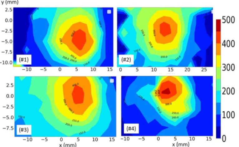
Powders velocities could also be compared for the different powders sprayed with same stand-off distance and similar spraying parameters. An example is given for Al2O3 powders
(#1, #2, #3) and ZrO2 powder (#4) with SoD=80 mm in Figure
5. Al2O3 #1 and #3 exhibited medium size particles while
Al2O3 #2 and ZrO2 #4were both fine (see Table 3). According
iso-velocity contours in Figure 5, supersonic velocities were in a spot region of around 8mm in diameter for all alumina powders #1 to #3 and no significant difference was observed for the fine alumina #2. For the denser and finer powder ZrO2
#4, the spot region at SoD of 80mm was more directional and velocities higher than 450m/s were measured. Such 80mm SoD was also used for preliminary spraying experiments.
Figure 5: Velocity maps of Al2O3 powders (#1, #2, #3) and
ZrO2 powder (#4), SoD 80 mm, HPCS (N2, 1MPa, 250°C) Maximum particle velocities of each powder #1 to #4 for increasing spraying distances are shown in Figure 6 (a) and Figure 6 (b) for HPCS and LPCS according spraying parameters listed Table 2. As expected, it is obvious that the maximum particle velocities decrease with increasing stand-off distance for all powders having similar spraying parameters. From Figure 6(a), it is also noticeable that the maximum velocities measured for powders #1 to #4 involving the HPCS equipment exhibited supersonic velocities up to at least a stand of distance of 120mm. It is also worth to note that maximum velocities of about 300m/s could be still measured in the central part of the jet up to a 160 mm spraying distance for all powders. The difference between powders exhibiting different particle size and density is not much pronounced for such gas parameter showing that both medium and coarse powders could be supersonically sprayed with a rather low pressure and temperature condition. However, for a higher gas pressure or a higher gas temperature, maximum particle velocities were accelerated up to 500m/s and above when measured at 80mm spraying distance. For this latter, the highest velocity was for the higher pressure compared to the higher gas temperature. From Figure 6(b), involving LPCS equipment with same gas temperature but lower gas pressure and air instead of nitrogen, maximum velocities of powders #1 to #3 are all 100m/s lower but the deceleration rate seems similar. Supersonic maximum velocity is reached at a stand of distance of 40mm. With such
velocity range, it is difficult to discriminate a significant influence of powders size and density
(a)
(b)
Figure 6: Maximum particle velocities at SoD: 40, 80, 120, 160 mm a) HPCS, b) LPCS
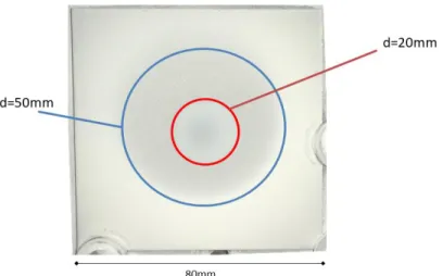
“Spot” spraying experiments: In cold spray, when the supersonic gas stream impinges the substrate, a normal shock wave is created. It results in a small stagnation region above the substrate exhibiting higher gas density and subsonic gas velocity. Such gradients and abrupt changes in local flow properties affect the velocity and trajectory of the entrained particles. As described by Pattison et al. [22]. the “bow shock” phenomenon will decelerate preferentially small particles and is also depending on the stand-off distance for given gas condition and nozzle geometry. For metallic powders, the deceleration and deviation of the particles in the stagnation zone drastically affect the resulting deposition efficiency [22]. In the case of agglomerated powders by cold spray involving hard ceramic material particles, the velocity range of the particles shall be probably limited to prevent the powder from acting only as an abrasive agent, as in the case of sandblasting. Therefore, unconventional gas parameters and longer spray distances were considered in this study. “Spot” experiments with a static position of the cold spray nozzle and large plates (80mm×80mm) were carried out in order to investigate the disturbance of the substrate on the resulting deposition behavior. An example of a top-surface view of a plate is given in Figure 7 for the Al2O3 powder #3 (medium size, calcinated
1000°C) with HPCS A parameters and a 80mm stand-off distance. The exposure time was 120s with a powder feed rate of 12.2 g/min.
Figure 7: Example of spot experiment (Al2O3 #3, 1.0 MPa /
250°C /N2, SoD 80mm)
From the image in Figure 7, it was evident that two concentric circles delimited three different zones with different deposition behaviour. In the central zone (d<20mm), some deposition
could be seen, while the particles in the surrounding zone (20mm<d<50mm) were obviously blown and propelled into the outer region by a radial flow due to the deviation of the normal flow. In the latter region, these particles were only stuck to the substrate. According to the velocity map measured at the same spraying distance without a substrate (see powder #3 in Figure 5), the central part of the deposited layer was intended for particles with velocities between 200 and 300 m/s. This "spot" experiment showed that the core of the particle stream could reach the substrate despite the presence of the bow shock and the deceleration induced. However, the disturbance generated by the substrate is clearly demonstrated in the region surrounding the core by the implementation of a blowing effect. This effect will be a key issue when the nozzle is moved.
“Line” experiments: “Line” experiments implementing a single track with the gun moving at 10 mm/s. were carried out with HPCS A parameters (See Table 2) at SoD=80 mm The corresponding top-surface SEM views for the three alumina (#1 to #3) and zirconia (#4) powders are presented in Figure 8.
Figure 8: SEM-BSE top-surface view on A2017 of #1, #2, #3 and #4
According the SEM views, particles are deposited and fragmented in each case. It resulted in thin film exhibiting a “chalk-like” structure with different covering homogeneity comparing the type of powders. Obviously, as-atomized powders #1 (alumina) and #4 (zirconia) had a different deposition behavior while they were with a nearly similar
maximum particle velocity of 425 m/s and 466 m/s respectively. Alumina #1 showed a very thin film of fragmented grains fully dispersed on the substrate and some isolated and moderately deformed splats having sizes close to the mean size or larger. Conversely, the zirconia track was with a thicker and much more homogenous deposited layer.
However, it seems that this rather uniform layer is formed by a close juxtaposition of isolated splats or groups of splats. It is interesting to note that zirconia powder have the finest grain size (76nm) and the higher density (5.62g/cm3). For this powder, some fine particles (<30µm) were embedded within the deposited layer (see Fig. 8). Concerning alumina powders #2 and #3 calcinated at 800°C and 1000°C, a similar behavior was evidenced but with a more uniform thin film of fragmented grains and more numerous isolated splats if compared to as-atomized alumina #1. Such splats had obviously a larger size than the mean particle size of the feedstock. The effect of the gas stream in the outer region of the powder jet (radial blast) was not similarly observed in case of these “line” experiments. The deposited powder remained adherent even after the gas flow has passed through.
The crystallites sizes of the deposited particles were compared with those of the feedstock. Results are summarized in Table 4. A slight decrease was measured for all samples but further analyses have to be achieved on other samples of Table 2 in order to confirm such difference.
Powder #1 #2 #3 #4
Feedstock 96nm 117 nm 146 nm 76 nm
Deposits: HPCS A, SoD 80mm 92 nm 102 nm 140 nm 56 nm
Table 4: Crystallite sizes (XRD) of feedstock and after CS
Conclusion
In this work, six different agglomerated ceramic powders were analyzed in order to investigate the role of their architecture on the deposition and impact behavior. As-atomized and calcinated agglomerated powders were with different characteristics: especially in terms of composition, particle size, porosity, density, specific area, crystallite sizes and micro-hardness. The particles flow jet was analyzed according velocity measurements without substrate for various spraying parameters involving both high-pressure (downstream injection) and low-pressure (upstream) cold spray and stand-off distances up to 160mm. Supersonic velocities, up to 500m/s at SoD 40mm, have been reached with the HPCS using low pressure and low temperature for this equipment. As expected, the maximum particles velocity is decreasing with increasing spraying distance together with a spreading of the jet. Supersonic velocities could be measured up to SoD=120mm. The same decrease was observed for LPCS with high pressure and low temperature for the equipment but supersonic velocities were enabled only up to SoD=80mm. According velocity maps, a more directional jet for the finer and denser zirconia powder was highlighted.
Preliminary spraying experiments were carried to better evaluate the role of the gas stream on the impact of particles at supersonic velocity. “Spot” experiments revealed the disturbance generated by the substrate. In general, the bow-shock, is responsible of the decrease of the particles velocity, and the "radial blast” of their expulsion towards the edges of the jet. However, in our case, the core of the particle flow could reach the substrate at 80mm. “Line” experiments were carried out to investigate the role of the powders. The three
alumina and the zirconia powders were deposited with the clear evidence of the fragmentation of the agglomerates. Such fragmentation is governed by the separation of the ultra-fine grains. It resulted in thin films with a “chalk-like” structure and different covering homogeneities comparing the calcination and the architecture of the powder were found. In this study, only thin films were deposited. But it puts forward the powder characteristics that will be necessary for the realization of ceramic cold spray deposit with agglomerated ceramic powders. The project's powders will further evolve to become more suitable for cold spray, in particular with more porous zirconia powders. New experiments, with LPCS at different stand-of-distance, of zirconia and yttrium spraying will be set up in order to compare these powders and deposits.
Acknowledgments
The authors would like to thanks all the partners of the CERASOL project (ANR-19-CE08-0009): IRCER (Limoges, France), Nanoé (Ballainvilliers, France) and Medicoat (Etupes, France), especially D. Chatelain at IRCER for his help to analyse the powders. The following persons at MINES-PSL are gratefully acknowledged for their help for XRD analyses (C. Monteiro ), TEM images and analyses (M. Sennour), cold spray experiments (J.–D. Bartout and F. Borit).
References
[1] A. Papyrin, et al., Cold spray technology, Elsevier, (Amsterdam, 2007).
[2] W. Li, « Solid-state additive manufacturing and repairing by cold spraying: A review », J. Mater. Sci., (2018), p. 18
[3] A. Moridi, et al., « Cold spray coating: review of material systems and future perspectives », Surf. Eng., vol. 30,
no 6, (2014) p. 369‑395, doi:
10.1179/1743294414Y.0000000270.
[4] H. Assadi, et al., « Cold spraying – A materials perspective », Acta Mater., vol. 116, (2016), p. 382‑407, doi: 10.1016/j.actamat.2016.06.034.
[5] D. Moreau, et al., « Cold Spray Coating of Submicronic Ceramic Particles on Poly(vinyl alcohol) in Dry and Hydrogel States », J. Therm. Spray Technol., vol. 26, no 5, (2017), p. 958‑969, doi: 10.1007/s11666-017-0551-8.
[6] A. M. Vilardell, et al., « Functionalized coatings by cold spray: An in vitro study of micro- and nanocrystalline hydroxyapatite compared to porous titanium », Mater. Sci.
Eng. C, vol. 87, (2018), p. 41‑49,
doi:10.1016/j.msec.2018.02.009.
[7] E. Kergourlay, et al., « First Cold Spraying of Carbonated Biomimetic Nanocrystalline Apatite on Ti6Al4V: Physical-Chemical, Microstructural, and Preliminary Mechanical Characterizations: First Cold Spraying of Carbonated Biomimetic Nanocrystalline », Adv. Eng. Mater.,
vol. 18, no 4, (2016), p. 496‑500, doi:
[8] M. Yamada, et al., « Cold Spraying of TiO2 Photocatalyst Coating With Nitrogen Process Gas », J. Therm.
Spray Technol., vol. 19, no 6, (2010), p. 1218‑1223, doi: 10.1007/s11666-010-9520-1.
[9] J.-O. Kliemann, et al., « Formation of Cold-Sprayed Ceramic Titanium Dioxide Layers on Metal Surfaces », J.
Therm. Spray Technol., vol. 20, no 1‑2, (2011), p. 292‑298, doi: 10.1007/s11666-010-9563-3.
[10] G.-J. Yang, et al., « Low temperature deposition and characterization of TiO2 photocatalytic film through cold spray », Appl. Surf. Sci., vol. 254, no 13, (2008), p. 3979‑3982, doi: 10.1016/j.apsusc.2007.12.016.
[11] L. Kong, et al., « Fabrication Of Y2O3 Coatings By Cold-Spray », Adv. Mater. Lett., vol. 10, no 3, (2019), p. 189‑192, doi: 10.5185/amlett.2019.2188.
[12] D. Seo, et al., « SiO2 and MoSi2 formation on Inconel 625 surface via SiC coating deposited by cold spray »,
Surf. Coat. Technol., vol. 206, no 11‑12, (2012), p. 2851‑2858, doi: 10.1016/j.surfcoat.2011.12.010.
[13] A. M. Vilardell, et al., « Dense nanostructured calcium phosphate coating on titanium by cold spray », J. Eur.
Ceram. Soc., vol. 37, no 4, (2017), p. 1747‑1755, doi: 10.1016/j.jeurceramsoc.2016.11.040.
[14] M. Yamada, et al., « Fabrication of Titanium Dioxide Photocatalyst Coatings by Cold Spray », J. Solid Mech. Mater.
Eng., vol. 3, no 2, (2009), p. 210‑216, doi: 10.1299/jmmp.3.210.
[15] N. T. Salim, et al., « The Synthesis of Titanium Dioxide (TiO2) Powder for Cold Spray Process », IOP Conf.
Ser. Mater. Sci. Eng., vol. 18, no 3, (2011), p. 032019, doi: 10.1088/1757-899X/18/3/032019.
[16] T. A. Rahim, et al., « Effect of Powder Calcination on the Cold Spray Titanium Dioxide Coating », Mater. Trans., vol. 57, no 8, (2016), p. 1345‑1350, doi: 10.2320/matertrans.T-M2016817.
[17] A. M. Vilardell, et al., « Feasibility of using low pressure cold gas spray for the spraying of thick ceramic hydroxyapatite coatings », Int. J. Appl. Ceram. Technol., vol. 16, no 1, (2019), p. 221‑229, doi: 10.1111/ijac.13088.
[18] J. Akedo, « Room Temperature Impact Consolidation (RTIC) of Fine Ceramic Powder by Aerosol Deposition Method and Applications to Microdevices », J. Therm. Spray
Technol., vol. 17, no 2, (2008), p. 181‑198, doi: 10.1007/s11666-008-9163-7.
[19] H. Park, et al., « Shock-induced plasticity and fragmentation phenomena during alumina deposition in the vacuum kinetic spraying process », Scr. Mater., vol. 100, (2015), p. 44‑47, doi: 10.1016/j.scriptamat.2014.12.008. [20] R. Moos, « An Overview of the Aerosol Deposition Method: Process Fundamentals and New Trends in Materials Applications », J. Ceram. Sci. Tech., no 03, (2015), doi: 10.4416/JCST2015-00018.
[21] R. Z. Huang, et al., « Study on the Influences of DPV-2000 Software Parameters on the Measured Results in Cold Spray », Proceedings of the International Thermal Spray
Conference, Seattle, Washington, USA ,2006.
[22] J. Pattison, et al., « Standoff distance and bow shock phenomena in the Cold Spray process », Surf. Coat. Technol.,
vol. 202, no 8, (2008), p. 1443‑1454, doi: