2018 — SDN-based traffic engineering in data centers, Interconnects, and Carrier Networks
199
0
0
Texte intégral
(2) This Creative Commons license allows readers to download this work and share it with others as long as the author is credited. The content of this work cannot be modified in any way or used commercially..
(3) BOARD OF EXAMINERS THIS THESIS HAS BEEN EVALUATED BY THE FOLLOWING BOARD OF EXAMINERS. Mr. Mohamed Cheriet, Thesis Supervisor Department of génie de la production automatisée, École de Technologie Supérieure Mr. Jean-Marc Robert, President of the Board of Examiners Department of génie logiciel et des technologies de l’information, École de Technologie Supérieure Mr. Michel Kadoch, Member of the jury Department of génie électrique, École de Technologie Supérieure Mrs. Halima Elbiaze, External Examiner Department of d’informatique, Université du Québec à Montréal. THIS THESIS WAS PRESENTED AND DEFENDED IN THE PRESENCE OF A BOARD OF EXAMINERS AND THE PUBLIC ON JANUARY 19TH , 2018 AT ÉCOLE DE TECHNOLOGIE SUPÉRIEURE.
(4)
(5) ACKNOWLEDGEMENTS I wish to express my deepest gratitude to Mohamed Cheriet, my thesis adviser, for his guidance, support, encouragement to hard work and to help me to grow as a researcher. I will always be indebted to him for believing in me and giving me the freedom in my research. I would like to thank all involved in GreenStar Network, Green Sustainable Telco Cloud (GSTC), V-WAN and Telus-Ciena projects. I would also like to thank CANARIE for supporting GreenStar Network; Ericsson, the NSERC, and MITACS for supporting the GSTC project; and Ciena, the NSERC, and MITACS for supporting the V-WAN project. It was a highly rewarding and enriching experience for me where I got to learn and conduct research on the cutting edge network technologies. I thank the board of examiners, Halima Elbiaze, Jean-Marc Robert, and Michel Kadoch, for their time and valuable comments and suggestions. I am grateful to my collaborator on all of the articles presented in this thesis: Kim Khoa Nguyen. I can not thank enough my friends and colleagues at the Synchromedia Lab for their great support throughout the time. A very special thanks to my family and friends for their encouragement and support that helped me sustain thus far..
(6)
(7) INGÉNIERIE DU TRAFIC BASÉE SUR SDN DANS LES CENTRES DE DONNÉES, LES INTERCONNEXIONS ET L’INFRASTRUCTURE RÉSEAU Tara Nath SUBEDI RÉSUMÉ La virtualisation des serveurs et le cloud computing ont augmenté les demandes en bande passante et en performances des réseaux des centres de données (DCN). Les principaux défis des DCN sont la maximisation de l’utilisation du réseau et la garantie d’une tolérance aux pannes pour résoudre les défaillances multiples de nœuds et de liaisons. Un environnement multitenant virtualisé et hautement dynamique se compose d’un grand nombre de stations terminales, entraînant un nombre important de flux qui remettent en cause l’évolutivité d’une solution qui maximise le débit du réseau. Les défis sont l’évolutivité, en termes d’apprentissage de l’adresse, de convergence des décisions de transmission et de taille de l’état de transfert, ainsi que la flexibilité pour l’envoi des flux avec la migration des machines virtuelles. Les centres de données géographiquement répartis sont interconnectés par l’intermédiaire de l’infrastructure de réseau des fournisseurs de services. Les fournisseurs de services offrent une connexion de réseau étendu (WAN) tels que des lignes privées et des circuits MPLS entre les centres de données. Les centres de données des opérateurs de réseau essaient de maximiser l’utilisation d’un tel réseau WAN déjà existant, c’est-à-dire l’interconnexion entre les centres de données (DCI) appliquée du côté réseau des centres de données. Alors que les fournisseurs de services des opérateurs de réseau tentent d’optimiser le cœur du réseau de l’opérateur. Parallèlement à l’adoption croissante des technologies ROADM, OTN et de la technologie de commutation de paquets, le réseau IP/MPLS-over-WDM traditionnel à deux couches a évolué pour devenir un réseau IP/MPLS-over-OTN sur DWDM à trois couches et la topologie de superposition définie est en train de changer pour des topologies dynamiques basées sur les demandes de trafic en temps réel. Les opérations sur le réseau sont ainsi divisées en trois sous-réseaux physiques: DCN, DCI overlay et l’infrastructure réseau multicouche de l’opérateur. La virtualisation de serveurs, le cloud computing et l’infrastructure réseau multicouche évolutive de l’opérateur défient l’ingénierie du trafic pour optimiser l’utilisation de tous ces sous-réseaux physiques. L’architecture émergente de réseau défini par logiciel (SDN) déplace le calcul des chemins vers un contrôleur centralisé, qui a une vue globale du réseau. Les opérateurs indiquent une forte préférence pour que le SDN soit interopérable entre plusieurs fournisseurs dans des réseaux de transport hétérogènes. SDN est un moyen naturel de créer une planification de contrôle unifié à travers plusieurs divisions administratives. Cette thèse contribue avec des techniques d’ingénierie de trafic basées sur SDN pour maximiser l’utilisation du réseau DCN, DCI et du réseau de transport. La première partie de la thèse porte sur l’ingénierie du trafic DCN. Les mécanismes d’acheminement traditionnels utilisant un seul chemin ne peuvent pas tirer parti des multiples chemins physiques disponibles. La solution MPTCP (Multipath Transmission Control Protocol) de.
(8) VIII. pointe utilise plusieurs chemins sélectionnés de manière aléatoire, mais ne peut pas fournir une capacité totale agrégée. De plus, cela fonctionne comme un processus TCP et ne supporte donc pas d’autres protocoles comme UDP. Pour résoudre ces problèmes, cette thèse présente une solution utilisant le routage multivoie adaptatif dans un réseau de deux couches avec des métriques statiques (capacité et latence), qui s’adapte aux ruptures de lien et de chemin. Cette solution fournit une agrégation dans le réseau des capacités des chemins aux flux individuels, ainsi que l’évolutivité et la Multi-Tenancy, en séparant les services de station terminale du réseau du fournisseur. Les résultats démontrent une amélioration de 14% de la pire utilisation de la bande passante de bissection, lorsque comparée au MPTCP avec 5 sous-flux. La deuxième partie de la thèse porte sur l’ingénierie du trafic DCI. Les approches existantes pour les services de réservation fournissent des capacités de réservation limitées, par ex. connexions limitées sur les liens renvoyés par le traceroute par rapport aux réseaux IP traditionnels. De plus, la plupart des approches existantes n’abordent pas la tolérance aux erreurs en cas de défaillance de nœuds ou de liaisons. Pour résoudre ces problèmes, cette thèse présente ECMP-comme l’algorithme de routage multi-chemins et la technique d’assignation de routes qui augmente le taux d’acceptation des réservations par rapport aux infrastructures de réservation de pointe dans les liaisons WAN entre centres de données. Ces réservations peuvent être configurées avec un nombre limité de règles de transfert statiques sur les commutateurs. Notre prototype fournit l’interface de service Web RESTful pour la gestion des événements de migration de liens et d’hôtes finaux et réachemine les chemins pour toutes les réservations affectées. Dans la dernière partie de la thèse, nous nous sommes concentrés sur l’ingénierie du trafic du réseau de transport multicouche. Les nouvelles tendances de trafic dynamiques dans les couches supérieures (par exemple le routage IP) nécessitent une configuration dynamique du transport optique pour rediriger le trafic, ce qui nécessite à son tour l’intégration de plusieurs couches de contrôle administratif. Lorsque plusieurs demandes de bande passante proviennent de différents nœuds dans différentes couches, un calcul séquentiel distribué ne peut pas optimiser le réseau entier. La plupart des recherches antérieures se sont concentrées sur le problème des deux couches, et les récentes études de recherche en trois couches se limitent au problème de dimensionnement de la capacité. Nous présentons dans cette thèse un modèle d’optimisation avec une formulation MILP pour le trafic dynamique dans un réseau à trois couches, ou nous avons tenu compte des contraintes technologiques uniques de la couche OTN distincte. Nos résultats expérimentaux montrent comment les valeurs de coût unitaire des différentes couches affectent le coût du réseau et les paramètres par la présence de plusieurs ensembles de charges de trafic. Nous démontrons également l’efficacité de notre approche heuristique proposée. Mots-clés: multipath, capacité de chemin agrégé, OpenFlow, routage, transfert, à la demande, à l’avance, réservation, SDN, inter-DC WAN, multicouche, paquet-optique, OTN, transport, optimisation.
(9) SDN-BASED TRAFFIC ENGINEERING IN DATA CENTERS, INTERCONNECTS, AND CARRIER NETWORKS Tara Nath SUBEDI ABSTRACT Server virtualization and cloud computing have escalated the bandwidth and performance demands on the DCN (data center network). The main challenges in DCN are maximizing network utilization and ensuring fault tolerance to address multiple node-and-link failures. A multitenant and highly dynamic virtualized environment consists of a large number of endstations, leading to a very large number of flows that challenge the scalability of a solution to network throughput maximization. The challenges are scalability, in terms of address learning, forwarding decision convergence, and forwarding state size, as well as flexibility for offloading with VM migration. Geographically distributed data centers are inter-connected through service providers’ carrier network. Service providers offer wide-area network (WAN) connection such as private lines and MPLS circuits between edges of data centers. DC sides of network operators try to maximize the utilization of such defined overlay WAN connection i.e. data center interconnection (DCI), which applies to edges of DC networks. Service provider sides of network operators try to optimize the core of carrier network. Along with the increasing adoption of ROADM, OTN, and packet switching technologies, traditional two-layer IP/MPLS-over-WDM network has evolved into three-layer IP/MPLS-over-OTN-over-DWDM network and once defined overlay topology is now transitioning to dynamic topologies based on on-demand traffic demands. Network operations are thus divided into three physical sub-networks: DCN, overlay DCI, and multi-layer carrier network. Server virtualization, cloud computing and evolving multilayer carrier network challenge traffic engineering to maximize utilization on all physical subnetworks. The emerging software-defined networking (SDN) architecture moves path computation towards a centralized controller, which has global visibility. Carriers indicate a strong preference for SDN to be interoperable between multiple vendors in heterogeneous transport networks. SDN is a natural way to create a unified control plane across multiple administrative divisions. This thesis contributes SDN-based traffic engineering techniques for maximizing network utilization of DCN, DCI, and carrier network. The first part of the thesis focuses on DCN traffic engineering. Traditional forwarding mechanisms using a single path are not able to take advantages of available multiple physical paths. The state-of-the-art MPTCP (Multipath Transmission Control Protocol) solution uses multiple randomly selected paths, but cannot give total aggregated capacity. Moreover, it works as a TCP process, and so does not support other protocols like UDP. To address these issues, this thesis presents a solution using adaptive multipath routing in a Layer-2 network with static (capacity and latency) metrics, which adapts link and path failures. This solution provides innetwork aggregated path capacity to individual flows, as well as scalability and multitenancy, by separating end-station services from the provider’s network. The results demonstrate an.
(10) X. improvement of 14% in the worst bisection bandwidth utilization, compared to the MPTCP with 5 sub-flows. The second part of the thesis focuses on DCI traffic engineering. The existing approaches to reservation services provide limited reservation capabilities, e.g. limited connections over links returned by the traceroute over traditional IP-based networks. Moreover, most existing approaches do not address fault tolerance in the event of node or link failures. To address these issues, this thesis presents ECMP-like multipath routing algorithm and forwarding assignment scheme that increase reservation acceptance rate compared to state-of-art reservation frameworks in the WAN-links between data centers, and such reservations can be configured with a limited number of static forwarding rules on switches. Our prototype provides the RESTful web service interface for link-fail event management and re-routes paths for all the affected reservations. In the final part of the thesis, we focused on multi-layer carrier network traffic engineering. New dynamic traffic trends in upper layers (e.g. IP routing) require dynamic configuration of the optical transport to re-direct the traffic, and this in turn requires an integration of multiple administrative control layers. When multiple bandwidth path requests come from different nodes in different layers, a distributed sequential computation cannot optimize the entire network. Most prior research has focused on the two-layer problem, and recent three-layer research studies are limited to the capacity dimensioning problem. In this thesis, we present an optimization model with MILP formulation for dynamic traffic in a three-layer network, especially taking into account the unique technological constraints of the distinct OTN layer. Our experimental results show how unit cost values of different layers affect network cost and parameters in the presence of multiple sets of traffic loads. We also demonstrate the effectiveness of our proposed heuristic approach. Keywords: multipath, aggregated path capacity, OpenFlow, routing, forwarding, on-demand, in-advance, reservation, SDN, inter-DC WAN, multi-layer, packet-optical, OTN, transport, optimization.
(11) TABLE OF CONTENTS Page INTRODUCTION . . . . . . . . . . . . . . . . . . . . . . . . . . . . . . . . . . . . . . . . . . . . . . . . . . . . . . . . . . . . . . . . . . . . . . . . . . . . . . . . 1 0.1 Context . . . . . . . . . . . . . . . . . . . . . . . . . . . . . . . . . . . . . . . . . . . . . . . . . . . . . . . . . . . . . . . . . . . . . . . . . . . . . . . . . . . 8 0.2 Problem statement . . . . . . . . . . . . . . . . . . . . . . . . . . . . . . . . . . . . . . . . . . . . . . . . . . . . . . . . . . . . . . . . . . . . . . . . 8 0.2.1 Multipath bandwidth aggregation in DCN . . . . . . . . . . . . . . . . . . . . . . . . . . . . . . . . . . . . 9 0.2.2 Bandwidth reservation in DCI . . . . . . . . . . . . . . . . . . . . . . . . . . . . . . . . . . . . . . . . . . . . . . . . 11 0.2.3 Optimization in carrier network . . . . . . . . . . . . . . . . . . . . . . . . . . . . . . . . . . . . . . . . . . . . . . 12 0.3 Outline of the thesis . . . . . . . . . . . . . . . . . . . . . . . . . . . . . . . . . . . . . . . . . . . . . . . . . . . . . . . . . . . . . . . . . . . . . 14 CHAPTER 1 LITERATURE REVIEW . . . . . . . . . . . . . . . . . . . . . . . . . . . . . . . . . . . . . . . . . . . . . . . . . . . . 15 1.1 Data Center Federation . . . . . . . . . . . . . . . . . . . . . . . . . . . . . . . . . . . . . . . . . . . . . . . . . . . . . . . . . . . . . . . . . 15 1.2 Multipath in DCN . . . . . . . . . . . . . . . . . . . . . . . . . . . . . . . . . . . . . . . . . . . . . . . . . . . . . . . . . . . . . . . . . . . . . . . 17 1.3 Bandwidth reservation in DCI . . . . . . . . . . . . . . . . . . . . . . . . . . . . . . . . . . . . . . . . . . . . . . . . . . . . . . . . . . 20 1.4 Optimization in multi-layer carrier network . . . . . . . . . . . . . . . . . . . . . . . . . . . . . . . . . . . . . . . . . . . 23 CHAPTER 2 OBJECTIVES AND GENERAL METHODOLOGY . . . . . . . . . . . . . . . . . . . . . 25 2.1 Objectives of the research . . . . . . . . . . . . . . . . . . . . . . . . . . . . . . . . . . . . . . . . . . . . . . . . . . . . . . . . . . . . . . 25 2.2 General methodology . . . . . . . . . . . . . . . . . . . . . . . . . . . . . . . . . . . . . . . . . . . . . . . . . . . . . . . . . . . . . . . . . . . 27 2.2.1 Adaptive multipath routing architecture for DCN . . . . . . . . . . . . . . . . . . . . . . . . . . . 27 2.2.2 Bandwidth reservation framework for DCI . . . . . . . . . . . . . . . . . . . . . . . . . . . . . . . . . . 30 2.2.3 Optimization model for multi-layer carrier network . . . . . . . . . . . . . . . . . . . . . . . . 33 CHAPTER 3 3.1 3.2 3.3. 3.4 3.5. 3.6 3.7. OPENFLOW-BASED IN-NETWORK LAYER-2 ADAPTIVE MULTIPATH AGGREGATION IN DATA CENTERS . . . . . . . . . . . . . . . . . . . . 37 Introduction . . . . . . . . . . . . . . . . . . . . . . . . . . . . . . . . . . . . . . . . . . . . . . . . . . . . . . . . . . . . . . . . . . . . . . . . . . . . . . 38 Related work . . . . . . . . . . . . . . . . . . . . . . . . . . . . . . . . . . . . . . . . . . . . . . . . . . . . . . . . . . . . . . . . . . . . . . . . . . . . 41 Adaptive Multipath Routing architecture . . . . . . . . . . . . . . . . . . . . . . . . . . . . . . . . . . . . . . . . . . . . . . 45 3.3.1 Adaptation to link failures . . . . . . . . . . . . . . . . . . . . . . . . . . . . . . . . . . . . . . . . . . . . . . . . . . . . 46 3.3.2 Multipath routing computation . . . . . . . . . . . . . . . . . . . . . . . . . . . . . . . . . . . . . . . . . . . . . . . 47 3.3.3 Path setup . . . . . . . . . . . . . . . . . . . . . . . . . . . . . . . . . . . . . . . . . . . . . . . . . . . . . . . . . . . . . . . . . . . . . . 50 Link selection . . . . . . . . . . . . . . . . . . . . . . . . . . . . . . . . . . . . . . . . . . . . . . . . . . . . . . . . . . . . . . . . . . . . . . . . . . . 53 Flow mapping to a multipath . . . . . . . . . . . . . . . . . . . . . . . . . . . . . . . . . . . . . . . . . . . . . . . . . . . . . . . . . . . 55 3.5.1 Address learning and PBB encapsulation . . . . . . . . . . . . . . . . . . . . . . . . . . . . . . . . . . . . 57 3.5.2 Multiple VNs and PBB decapsulation . . . . . . . . . . . . . . . . . . . . . . . . . . . . . . . . . . . . . . . 59 Scalability in a large topology . . . . . . . . . . . . . . . . . . . . . . . . . . . . . . . . . . . . . . . . . . . . . . . . . . . . . . . . . . 60 Evaluation . . . . . . . . . . . . . . . . . . . . . . . . . . . . . . . . . . . . . . . . . . . . . . . . . . . . . . . . . . . . . . . . . . . . . . . . . . . . . . . 63 3.7.1 Path aggregation for a single TCP session . . . . . . . . . . . . . . . . . . . . . . . . . . . . . . . . . . . 64 3.7.2 The TCP’s CWND and segment sequence number . . . . . . . . . . . . . . . . . . . . . . . . . 65 3.7.3 Dynamic adaptation to link and path failures . . . . . . . . . . . . . . . . . . . . . . . . . . . . . . . . 67 3.7.4 36 edge node topology . . . . . . . . . . . . . . . . . . . . . . . . . . . . . . . . . . . . . . . . . . . . . . . . . . . . . . . . 68 3.7.4.1 Bisection bandwidth . . . . . . . . . . . . . . . . . . . . . . . . . . . . . . . . . . . . . . . . . . . . . . 68.
(12) XII. 3.8 3.9. 3.7.4.2 Forwarding table size . . . . . . . . . . . . . . . . . . . . . . . . . . . . . . . . . . . . . . . . . . . . . 72 3.7.4.3 Convergence time . . . . . . . . . . . . . . . . . . . . . . . . . . . . . . . . . . . . . . . . . . . . . . . . . 72 Conclusion . . . . . . . . . . . . . . . . . . . . . . . . . . . . . . . . . . . . . . . . . . . . . . . . . . . . . . . . . . . . . . . . . . . . . . . . . . . . . . . 73 Acknowledgments . . . . . . . . . . . . . . . . . . . . . . . . . . . . . . . . . . . . . . . . . . . . . . . . . . . . . . . . . . . . . . . . . . . . . . . 74. CHAPTER 4. 4.1 4.2. 4.3 4.4. 4.5. 4.6. 4.7 4.8. SDN-BASED FAULT-TOLERANT ON-DEMAND AND INADVANCE BANDWIDTH RESERVATION IN DATA CENTER INTERCONNECTS . . . . . . . . . . . . . . . . . . . . . . . . . . . . . . . . . . . . . . . . . . . . . . . . . . . . . . . . . . 75 Introduction . . . . . . . . . . . . . . . . . . . . . . . . . . . . . . . . . . . . . . . . . . . . . . . . . . . . . . . . . . . . . . . . . . . . . . . . . . . . . . 76 Related work . . . . . . . . . . . . . . . . . . . . . . . . . . . . . . . . . . . . . . . . . . . . . . . . . . . . . . . . . . . . . . . . . . . . . . . . . . . . 79 4.2.1 Bandwidth reservation architectures . . . . . . . . . . . . . . . . . . . . . . . . . . . . . . . . . . . . . . . . . 80 4.2.2 Algorithms for bandwidth reservation . . . . . . . . . . . . . . . . . . . . . . . . . . . . . . . . . . . . . . . 81 Problem description . . . . . . . . . . . . . . . . . . . . . . . . . . . . . . . . . . . . . . . . . . . . . . . . . . . . . . . . . . . . . . . . . . . . . 83 Topology, time and reservation models . . . . . . . . . . . . . . . . . . . . . . . . . . . . . . . . . . . . . . . . . . . . . . . . 85 4.4.1 Topology model . . . . . . . . . . . . . . . . . . . . . . . . . . . . . . . . . . . . . . . . . . . . . . . . . . . . . . . . . . . . . . . 86 4.4.2 Time model . . . . . . . . . . . . . . . . . . . . . . . . . . . . . . . . . . . . . . . . . . . . . . . . . . . . . . . . . . . . . . . . . . . . 87 4.4.3 Reservation model . . . . . . . . . . . . . . . . . . . . . . . . . . . . . . . . . . . . . . . . . . . . . . . . . . . . . . . . . . . . 87 Proposed solutions . . . . . . . . . . . . . . . . . . . . . . . . . . . . . . . . . . . . . . . . . . . . . . . . . . . . . . . . . . . . . . . . . . . . . . 91 4.5.1 Determining the available bandwidth and path computation (Solution for Problem P1) . . . . . . . . . . . . . . . . . . . . . . . . . . . . . . . . . . . . . . . . . . . . . . . . . . . . 91 4.5.1.1 Determining the available bandwidth of a link (Solution for Problem P1-1) . . . . . . . . . . . . . . . . . . . . . . . . . . . . . . . . . . . . . . 91 4.5.1.2 Path compute: ECMP-like multiple paths consideration (Solution for Problem P1-2) . . . . . . . . . . . . . . . . . . . . . . . . . . . . . . . . . . . . . . 92 4.5.2 Path setup and scalable forwarding (Solution for Problem P2) . . . . . . . . . . . . . 94 4.5.2.1 Co-existence of reservation and best-effort traffic . . . . . . . . . . . . . . . 95 4.5.2.2 Path setup . . . . . . . . . . . . . . . . . . . . . . . . . . . . . . . . . . . . . . . . . . . . . . . . . . . . . . . . . . 95 4.5.2.3 Tunnel assignments for scalable forwarding . . . . . . . . . . . . . . . . . . . . . 97 4.5.3 Fault tolerances to (ReRoute on) link/path failures and end-host migrations (Solution for Problem P3) . . . . . . . . . . . . . . . . . . . . . . . . . . . . . . . . . . . . . . .100 4.5.4 SDN-based fault-tolerant bandwidth reservation (SFBR) architecture . . . . . . . . . . . . . . . . . . . . . . . . . . . . . . . . . . . . . . . . . . . . . . . . . . . . . . . . . . . . . . . . . . .102 Approach evaluation . . . . . . . . . . . . . . . . . . . . . . . . . . . . . . . . . . . . . . . . . . . . . . . . . . . . . . . . . . . . . . . . . . .104 4.6.1 Acceptance rates . . . . . . . . . . . . . . . . . . . . . . . . . . . . . . . . . . . . . . . . . . . . . . . . . . . . . . . . . . . . .106 4.6.2 Forwarding rules scalability . . . . . . . . . . . . . . . . . . . . . . . . . . . . . . . . . . . . . . . . . . . . . . . . .108 4.6.3 Link failure and migration handling . . . . . . . . . . . . . . . . . . . . . . . . . . . . . . . . . . . . . . . .110 4.6.4 Affected reservation lookup efficiency . . . . . . . . . . . . . . . . . . . . . . . . . . . . . . . . . . . . . .111 4.6.5 Best-effort versus reservation flows . . . . . . . . . . . . . . . . . . . . . . . . . . . . . . . . . . . . . . . . .113 Conclusion . . . . . . . . . . . . . . . . . . . . . . . . . . . . . . . . . . . . . . . . . . . . . . . . . . . . . . . . . . . . . . . . . . . . . . . . . . . . . .114 Acknowledgments . . . . . . . . . . . . . . . . . . . . . . . . . . . . . . . . . . . . . . . . . . . . . . . . . . . . . . . . . . . . . . . . . . . . . .114. CHAPTER 5. SDN-BASED OPTIMIZATION MODEL OF MULTI-LAYER TRANSPORT NETWORK DYNAMIC TRAFFIC ENGINEERING . . . . . . . . . . . . . . . . . . . . . . . . . . . . . . . . . . . . . . . . . . . . . . . . . . . . . . . . . . . . . . . . . . . . . . . . . . . . . . . .115.
(13) XIII. 5.1 5.2 5.3 5.4 5.5 5.6 5.7. 5.8 5.9. Introduction . . . . . . . . . . . . . . . . . . . . . . . . . . . . . . . . . . . . . . . . . . . . . . . . . . . . . . . . . . . . . . . . . . . . . . . . . . . . .116 Related work . . . . . . . . . . . . . . . . . . . . . . . . . . . . . . . . . . . . . . . . . . . . . . . . . . . . . . . . . . . . . . . . . . . . . . . . . . .118 Traffic mapping in an OTN network . . . . . . . . . . . . . . . . . . . . . . . . . . . . . . . . . . . . . . . . . . . . . . . . . .120 Modeling of the three-layer network . . . . . . . . . . . . . . . . . . . . . . . . . . . . . . . . . . . . . . . . . . . . . . . . . .122 Optimization model . . . . . . . . . . . . . . . . . . . . . . . . . . . . . . . . . . . . . . . . . . . . . . . . . . . . . . . . . . . . . . . . . . . .124 MLO heuristics . . . . . . . . . . . . . . . . . . . . . . . . . . . . . . . . . . . . . . . . . . . . . . . . . . . . . . . . . . . . . . . . . . . . . . . . .133 Experimental results . . . . . . . . . . . . . . . . . . . . . . . . . . . . . . . . . . . . . . . . . . . . . . . . . . . . . . . . . . . . . . . . . . .138 5.7.1 Topology . . . . . . . . . . . . . . . . . . . . . . . . . . . . . . . . . . . . . . . . . . . . . . . . . . . . . . . . . . . . . . . . . . . . .139 5.7.2 Demand . . . . . . . . . . . . . . . . . . . . . . . . . . . . . . . . . . . . . . . . . . . . . . . . . . . . . . . . . . . . . . . . . . . . . . .139 5.7.3 Cost values . . . . . . . . . . . . . . . . . . . . . . . . . . . . . . . . . . . . . . . . . . . . . . . . . . . . . . . . . . . . . . . . . . .141 5.7.4 Numerical results . . . . . . . . . . . . . . . . . . . . . . . . . . . . . . . . . . . . . . . . . . . . . . . . . . . . . . . . . . . .142 5.7.4.1 Visualization of results . . . . . . . . . . . . . . . . . . . . . . . . . . . . . . . . . . . . . . . . . . .142 5.7.4.2 Three use cases . . . . . . . . . . . . . . . . . . . . . . . . . . . . . . . . . . . . . . . . . . . . . . . . . . .143 5.7.5 Heuristics results . . . . . . . . . . . . . . . . . . . . . . . . . . . . . . . . . . . . . . . . . . . . . . . . . . . . . . . . . . . . .146 Conclusion . . . . . . . . . . . . . . . . . . . . . . . . . . . . . . . . . . . . . . . . . . . . . . . . . . . . . . . . . . . . . . . . . . . . . . . . . . . . . .146 Acknowledgments . . . . . . . . . . . . . . . . . . . . . . . . . . . . . . . . . . . . . . . . . . . . . . . . . . . . . . . . . . . . . . . . . . . . . .147. CHAPTER 6 GENERAL DISCUSSIONS . . . . . . . . . . . . . . . . . . . . . . . . . . . . . . . . . . . . . . . . . . . . . . . .149 6.1 Multipath in DCN . . . . . . . . . . . . . . . . . . . . . . . . . . . . . . . . . . . . . . . . . . . . . . . . . . . . . . . . . . . . . . . . . . . . . .149 6.2 Bandwidth reservation in DCI . . . . . . . . . . . . . . . . . . . . . . . . . . . . . . . . . . . . . . . . . . . . . . . . . . . . . . . . .150 6.3 Optimization in multi-layer carrier network . . . . . . . . . . . . . . . . . . . . . . . . . . . . . . . . . . . . . . . . . .152 6.4 Combination in general framework . . . . . . . . . . . . . . . . . . . . . . . . . . . . . . . . . . . . . . . . . . . . . . . . . . .153 CONCLUSION AND RECOMMENDATIONS . . . . . . . . . . . . . . . . . . . . . . . . . . . . . . . . . . . . . . . . . . . . . .155 BIBLIOGRAPHY . . . . . . . . . . . . . . . . . . . . . . . . . . . . . . . . . . . . . . . . . . . . . . . . . . . . . . . . . . . . . . . . . . . . . . . . . . . . . .158.
(14)
(15) LIST OF TABLES Page Table 3.1. Ingress node’s uplink forwarding . . . . . . . . . . . . . . . . . . . . . . . . . . . . . . . . . . . . . . . . . . . . . . . 59. Table 3.2. Egress node’s downlink forwarding . . . . . . . . . . . . . . . . . . . . . . . . . . . . . . . . . . . . . . . . . . . . . 59. Table 3.3. Experiment scenarios and results. . . . . . . . . . . . . . . . . . . . . . . . . . . . . . . . . . . . . . . . . . . . . . . . 65. Table 4.1. Topology DB model . . . . . . . . . . . . . . . . . . . . . . . . . . . . . . . . . . . . . . . . . . . . . . . . . . . . . . . . . . . . . 86. Table 4.2. TB list mapping per outgoing link of switches . . . . . . . . . . . . . . . . . . . . . . . . . . . . . . . . . 87. Table 4.3. Reservation and tunnels mappings . . . . . . . . . . . . . . . . . . . . . . . . . . . . . . . . . . . . . . . . . . . . . . 88. Table 4.4. Node’s tunnel forwarding rules. . . . . . . . . . . . . . . . . . . . . . . . . . . . . . . . . . . . . . . . . . . . . . . . . . 99. Table 5.1. ODUk client mapping/multiplexing in OTUk server of 1.24G TSG: number of TS required per ODUk times maximum number of ODUk client supports . . . . . . . . . . . . . . . . . . . . . . . . . . . . . . . . . . . . . . . . . . . . . . . . . . . . . . . . . . . . . . . . . . .121. Table 5.2. tIP Traffic demands with 20, 50 and 90% fraction of 50G node capacity (ai j = a ji ) . . . . . . . . . . . . . . . . . . . . . . . . . . . . . . . . . . . . . . . . . . . . . . . . . . . . . . . . . . . . . .140. Table 5.3. tOP Traffic demands ( with 20, 50 and 90% of L1-CE boundary point-pairs (ai j = a ji ) . . . . . . . . . . . . . . . . . . . . . . . . . . . . . . . . . . . . . . . . . . . . . . . . . . . . . . . . . . .140. Table 5.4. Demand Scenario . . . . . . . . . . . . . . . . . . . . . . . . . . . . . . . . . . . . . . . . . . . . . . . . . . . . . . . . . . . . . . .141. Table 6.1. TE approach classification . . . . . . . . . . . . . . . . . . . . . . . . . . . . . . . . . . . . . . . . . . . . . . . . . . . . . .154.
(16)
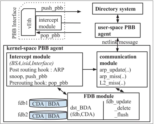
(17) LIST OF FIGURES Page Figure 0.1. Traditional versus SDN . . . . . . . . . . . . . . . . . . . . . . . . . . . . . . . . . . . . . . . . . . . . . . . . . . . . . . . . . . 6. Figure 0.2. Unified control in network . . . . . . . . . . . . . . . . . . . . . . . . . . . . . . . . . . . . . . . . . . . . . . . . . . . . . . 7. Figure 0.3. Intra-DC, DCI and multi-layer carrier network . . . . . . . . . . . . . . . . . . . . . . . . . . . . . . . . 9. Figure 0.4. Multipath topology example . . . . . . . . . . . . . . . . . . . . . . . . . . . . . . . . . . . . . . . . . . . . . . . . . . . 10. Figure 0.5. DC level WAN topology and closer look at physical connectivity for a pair of DC . . . . . . . . . . . . . . . . . . . . . . . . . . . . . . . . . . . . . . . . . . . . . . . . . . . . . . . . . . . . . . . . . 11. Figure 0.6. Multi-layered network and different routing mechanisms . . . . . . . . . . . . . . . . . . . . 13. Figure 2.1. Experimental testbed for DCN . . . . . . . . . . . . . . . . . . . . . . . . . . . . . . . . . . . . . . . . . . . . . . . . . 29. Figure 2.2. Experimental testbed for DCI . . . . . . . . . . . . . . . . . . . . . . . . . . . . . . . . . . . . . . . . . . . . . . . . . . 32. Figure 3.1. Multipath topology example . . . . . . . . . . . . . . . . . . . . . . . . . . . . . . . . . . . . . . . . . . . . . . . . . . . 39. Figure 3.2. AMR architecture . . . . . . . . . . . . . . . . . . . . . . . . . . . . . . . . . . . . . . . . . . . . . . . . . . . . . . . . . . . . . . . 46. Figure 3.3. Edmonds-Karp vs. AMR . . . . . . . . . . . . . . . . . . . . . . . . . . . . . . . . . . . . . . . . . . . . . . . . . . . . . . . 48. Figure 3.4. Flow and group entries for X-Y s-t-pair on the given topology (Figure 3.1) . . . . . . . . . . . . . . . . . . . . . . . . . . . . . . . . . . . . . . . . . . . . . . . . . . . . . . . . . . . . . . . . . . . . . . 51. Figure 3.5. Fairness on multiple flows . . . . . . . . . . . . . . . . . . . . . . . . . . . . . . . . . . . . . . . . . . . . . . . . . . . . . . 52. Figure 3.6. Link selection example . . . . . . . . . . . . . . . . . . . . . . . . . . . . . . . . . . . . . . . . . . . . . . . . . . . . . . . . . 54. Figure 3.7. Internal components on a host. . . . . . . . . . . . . . . . . . . . . . . . . . . . . . . . . . . . . . . . . . . . . . . . . . 55. Figure 3.8. Experimental deployment of PBB . . . . . . . . . . . . . . . . . . . . . . . . . . . . . . . . . . . . . . . . . . . . . 56. Figure 3.9. PBB agent and directory system architecture . . . . . . . . . . . . . . . . . . . . . . . . . . . . . . . . . 57. Figure 3.10. PBB agents and directory system communication . . . . . . . . . . . . . . . . . . . . . . . . . . . . 58. Figure 3.11. Multiple OpenFlow domains (dotted rectangle), single Directory System and MAC prefix concept . . . . . . . . . . . . . . . . . . . . . . . . . . . . . . . . . . . . . . . . . . . . . . . 60. Figure 3.12. Snapshot at 50th second during TCP Iperf session . . . . . . . . . . . . . . . . . . . . . . . . . . . . 64.
(18) XVIII. Figure 3.13. TCP response on 400MB transfer on different scenarios . . . . . . . . . . . . . . . . . . . . . 66. Figure 3.14. Egress node interfaces throughput variation on different link failures during UDP session . . . . . . . . . . . . . . . . . . . . . . . . . . . . . . . . . . . . . . . . . . . . . . . . . . . . 68. Figure 3.15. Topology with 36 host nodes . . . . . . . . . . . . . . . . . . . . . . . . . . . . . . . . . . . . . . . . . . . . . . . . . . . 69. Figure 3.16. average distance (AD) vs. bisection throughput with the probability density of AD . . . . . . . . . . . . . . . . . . . . . . . . . . . . . . . . . . . . . . . . . . . . . . . . . . . . . . 70. Figure 3.17. MPTCP vs. AMR . . . . . . . . . . . . . . . . . . . . . . . . . . . . . . . . . . . . . . . . . . . . . . . . . . . . . . . . . . . . . . . 71. Figure 4.1. DC level WAN topology and closer look at physical connectivity for a pair of DC . . . . . . . . . . . . . . . . . . . . . . . . . . . . . . . . . . . . . . . . . . . . . . . . . . . . . . . . . . . . . . . . . 77. Figure 4.2. High-level framework . . . . . . . . . . . . . . . . . . . . . . . . . . . . . . . . . . . . . . . . . . . . . . . . . . . . . . . . . . 85. Figure 4.3. An illustration of topology DB Model . . . . . . . . . . . . . . . . . . . . . . . . . . . . . . . . . . . . . . . . . 86. Figure 4.4. An illustration of TB list of an outgoing link . . . . . . . . . . . . . . . . . . . . . . . . . . . . . . . . . . 88. Figure 4.5. Reservation mapping with tunnels and bandwidth . . . . . . . . . . . . . . . . . . . . . . . . . . . . 89. Figure 4.6. hwPathSetup/Tear Modeling (“internal” edge Controller maps reservation flow to tunnel(s) on ingress internal edge node) . . . . . . . . . . . . . . . . . . 96. Figure 4.7. Tunnel assignments for scalable forwarding . . . . . . . . . . . . . . . . . . . . . . . . . . . . . . . . . . 98. Figure 4.8. SFBR Architecture . . . . . . . . . . . . . . . . . . . . . . . . . . . . . . . . . . . . . . . . . . . . . . . . . . . . . . . . . . . . .103. Figure 4.9. On-demand and In-advance Reservations workflow . . . . . . . . . . . . . . . . . . . . . . . . .103. Figure 4.10. Topology and reservation visualization . . . . . . . . . . . . . . . . . . . . . . . . . . . . . . . . . . . . . . .105. Figure 4.11. link’s time bandwidth visualization . . . . . . . . . . . . . . . . . . . . . . . . . . . . . . . . . . . . . . . . . . .106. Figure 4.12. Acceptance rates of PathCompute, Sahni and traceroute for the fixed-bandwidth problem . . . . . . . . . . . . . . . . . . . . . . . . . . . . . . . . . . . . . . . . . . . . . . . . . . . . . .108. Figure 4.13. Our scalable forwarding needs fewer rules to fully exploit network capacity . . . . . . . . . . . . . . . . . . . . . . . . . . . . . . . . . . . . . . . . . . . . . . . . . . . . . . . . . . . . . . . . . . . . . . . . .110. Figure 4.14. Failure handling . . . . . . . . . . . . . . . . . . . . . . . . . . . . . . . . . . . . . . . . . . . . . . . . . . . . . . . . . . . . . . . .111. Figure 4.15. Affected reservation lookup time versus reservation present . . . . . . . . . . . . . . . .112.
(19) XIX. Figure 4.16. Service differentiation and bandwidth guarantee on best-effort versus reservation flow . . . . . . . . . . . . . . . . . . . . . . . . . . . . . . . . . . . . . . . . . . . . . . . . . . . . . . . .113. Figure 5.1. vlink’s capacity C is discrete variable. . . . . . . . . . . . . . . . . . . . . . . . . . . . . . . . . . . . . . . . .122. Figure 5.2. Multi-layered network and different routing mechanisms . . . . . . . . . . . . . . . . . . .123. Figure 5.3. Multi layer architecture and topology model . . . . . . . . . . . . . . . . . . . . . . . . . . . . . . . . .125. Figure 5.4. Formulation notation. . . . . . . . . . . . . . . . . . . . . . . . . . . . . . . . . . . . . . . . . . . . . . . . . . . . . . . . . . .126. Figure 5.5. extended NSFNET multi layer topology. . . . . . . . . . . . . . . . . . . . . . . . . . . . . . . . . . . . . .139. Figure 5.6. Extended NSFNET multi layer topology and states . . . . . . . . . . . . . . . . . . . . . . . . .143. Figure 5.7. Effect of varying COP and traffic loads . . . . . . . . . . . . . . . . . . . . . . . . . . . . . . . . . . . . . . .143. Figure 5.8. Effect of varying CLP_S and traffic loads . . . . . . . . . . . . . . . . . . . . . . . . . . . . . . . . . . . . . .144. Figure 5.9. Effect of individual/integrated approach and traffic loads . . . . . . . . . . . . . . . . . . .144. Figure 5.10. Heuristic versus optimization on individual/integrated approach and traffic loads . . . . . . . . . . . . . . . . . . . . . . . . . . . . . . . . . . . . . . . . . . . . . . . . . . . . . . . . . . . . . . . .147.
(20)
(21) LIST OF ALGORITHMS. Algorithm 3.1. multiPathCompute(G,s,t) . . . . . . . . . . . . . . . . . . . . . . . . . . . . . . . . . 49. Algorithm 3.2. storePath(s,t,P,pC) . . . . . . . . . . . . . . . . . . . . . . . . . . . . . . . . . . . . . . 49. Algorithm 3.3. multiPathSetup(t,s) . . . . . . . . . . . . . . . . . . . . . . . . . . . . . . . . . . . . . 50. Algorithm 4.1. aTB(edge, ts , te ) : available Time-Bandwidth . . . . . . . . . . . . . . . . . . . 91. Algorithm 4.2. PathCompute(G, s, d, ts , te , β ) . . . . . . . . . . . . . . . . . . . . . . . . . . . . . .93. Algorithm 4.3. ReRoute() . . . . . . . . . . . . . . . . . . . . . . . . . . . . . . . . . . . . . . . . . . . .101. Algorithm 4.4. linkFailAffect(u, v, nowTime) . . . . . . . . . . . . . . . . . . . . . . . . . . . . . .101. Algorithm 5.1. MLOHeuristic(MG, tLP ,tOP ,tIP , costs) . . . . . . . . . . . . . . . . . . . . . . . .135. Algorithm 5.2. single_bandwidth_path(G, d) . . . . . . . . . . . . . . . . . . . . . . . . . . . . . . 135. Algorithm 5.3. k-bandwidth-paths(G, d) . . . . . . . . . . . . . . . . . . . . . . . . . . . . . . . . . 136. Algorithm 5.4. reserveCapacity(G, hd , path, vlink_key ← None) . . . . . . . . . . . . . . . . 137. Algorithm 5.5. reroute_L2.5_vlinks(G, L2.5links, delta) . . . . . . . . . . . . . . . . . . . . . . 138.
(22)
(23) LIST OF ABBREVIATIONS AMR. Adaptive Multipath Routing. API. Application Programming Interface. ASIC. Application Specific Integrated Circuit. BA. Backbone Address. CBC. Coin-or Branch and Cut. CBR. Constraint Based Routing. CE. Customer Equipment. CTP. Connection Termination Point. CTPP. CTP Pool. CWND. Congestion WiNDow. DC. Data Center. DCN. Data Center Network. DiffServ. Differentiated Services. DPID. DataPath ID. DWDM. Dense Wavelength-Division Multiplexing. ECMP. Equal-Cost Multi-Path. FDB. Forwarding DataBase. FEC. Forwarding Equivalent Class. GMPLS. Generalized MPLS.
(24) XXIV. GRE. Generic Routing Encapsulation. GSTC. Green Sustainable Telco Cloud. IntServ. Integrated Service. IP. Internet Protocol. IS-IS. Intermediate System-to-Intermediate System. L1. Layer-1. L2. Layer-2. L3. Layer-3. LLDP. Link Layer Discovery Protocol. LSP. Label Switched Path. MAC. Media Access Control Address. MEC. Multi-chassis EtherChannel. MPLS. Multiple Protocol Label Switching. MPLS-TE. MPLS with Traffic Engineering. MPTCP. MultiPath Transmission Control Protocol. MRM. Multipath Routing Module. MST. Multiple Spanning Tree. NBI. North-Bound Interface. NMS. Network Management System. OCh. Optical Channel.
(25) XXV. ODU. Optical Data Unit. ONF. Open Networking Foundation. OTN. Optical Transport Network. OVS. Open vSwitch. PBB. Provider Backbone Bridge. PCE. Path Computation Element. PCEP. PCE communication Protocol. PE. Provider Equipment. PMAC. Pseudo MAC. PVST. Per-VLAN Spanning Tree. QoS. Quality of Service. REST. REpresentational State Transfer. resvID. reservation IDentifier. RSVP. ReSource reserVation Protocol. RSVP-TE. RSVP with TE extensions. RTT. Round Trip Time. SBI. South-Bound Interface. SDN. Software Defined Networking. SID. Service instance IDentifier. SPB. Shortest Path Bridging.
(26) XXVI. SPBM. SPB-MAC. SPBV. SPB-VID. STP. Service Termination Point. STP. Spanning Tree Protocol. TB. Time-Bandwidth. TCAM. Ternary Content Addressable Memory. TDM. Topology Discovery Module. TE. Traffic Engineering. ToP. Top of Pod. ToR. Top of Rack. ToS. Top of Super-pod. TRILL. TRansparent Interconnection of Lots of Links. TS. Time-Slot. TSG. Time-Slot Granularity. TTL. Time to Live. TTP. Trail Termination Point. VC. Virtual Circuit. VDC. Virtual Data Center. vEth. virtual Ethernet interface. VM. Virtual Machine.
(27) XXVII. VN. Virtual Network. vSwitch. virtual Switch. VTD. Virtual Topology Design. WAN. Wide-Area Network. WPS. Weighted Probabilistic Selection. WRR. Weighted Round-Robin.
(28)
(29) INTRODUCTION A network is typically configured by interconnecting physical devices such as routers and switches. A major problem with the network is to adapt to the dynamic nature of the interconnection and traffic pattern. An important technique to address this problem is traffic engineering, which optimizes the network and improves network robustness. As traffic demand increases, traffic engineering can reduce the service degradation due to congestion and failure, e.g. link failure. The aim of this thesis is to provide SDN-based traffic engineering techniques for: A1) maximizing network utilization, A2) fault tolerance to address multiple node-and-link failures, and A3) scalability in the forwarding table, of Data Centers, Interconnects and Carrier Networks. We contribute in three approaches, dealing with each problem: P1) multipath bandwidth aggregation P2) bandwidth reservation and P3) optimization.. Data Center Network A Data Center Network (DCN) is a communication network interconnecting the entire pool of resources (computational, storage, network) within a data center facility. A conventional data center network comprises: servers that manage workloads; switches/routers that connect devices together and perform forwarding functions; controllers that manage the workflow between network devices and gateways that serve as the junctions between DCNs and the carrier network or the Internet. In recent decades, data centers have benefited immensely from virtualization, that enables server consolidation, application isolation, workload migration and faster deployment times, which enables DC providers to pool their computing resources for multiple consumers. The delivery of on-demand computing resources over the internet on a pay-for-use basis is called cloud computing. Virtualization and cloud computing have promises for many organizations.
(30) 2. to move in cloud environments without making sizable capital investments in computing hardware. DCN was designed under the safe assumption that each node was connected to the access port of an end-of-row switch in the network and it corresponded to one server running the single instance of an Operating System (OS). Another assumption was that it would not move to another physical server. Server virtualization has invalidated these assumptions and has posed some new challenges for the design of DCNs, that include scaling of the network for virtualization, VM mobility, management complexity and support for convergence (Bari et al., 2013). In this environment, the traditional tiered tree topology gives poor reliability and leads to oversubscribed any-to-any network design, and forwarding along a tree constrains workload placement (Greenberg et al., 2008, 2009). To support high bisection bandwidth and fault-tolerance, in modern data center network, host servers are often built with multiple interfaces, and their network topology consists of multiple redundant links, resulting in a multipath physical network (Guo et al., 2008; Greenberg et al., 2009). Examples of multipath network topologies include DCell (Guo et al., 2008), BCube (Guo et al., 2009), and Fat tree (Al-Fares et al., 2008), as well as the flat-mesh architecture, an Ethernet fabric (Brocade), for example.. Data Center Interconnect Data center interconnect (DCI) refers to the networking of two or more geographically distributed data centers. Such an inter data center network provides a dynamic and virtualized environment when augmented with cloud infrastructure supporting end-host migration. Most small to medium-sized enterprises purchase Carrier services from service providers instead of building and maintaining their own network infrastructure to be more cost-effective to site interconnection and data center interconnection. Many large-scale scientific and commercial applications produce large amounts of data, in the order of terabytes to petabytes. Given the need for low-latency and high-throughput data transfers, the DCI is often a dedicated network,.
(31) 3. distinct from the WAN that connects with ISPs to reach end users (Hong et al., 2013). The most effective transport for the DCI is through private lines and MPLS circuits, which is offered by underlying packet-optical carrier network connected to the gateways of data centers. Here the DCI topology is a static overlay topology, i.e. links between two end-ports are fixed. DCI is an expensive resource, with the amortized annual cost of 100s millions of dollars, as it provides 100s of Gbps to Tbps of capacity over long distances. Moreover, DCI is provisioned for peak usage to avoid congestion. However, applications send as much traffic as they want and whenever they want to, regardless of the current state of the network or other applications, which leads to networks swinging between over and under subscription. The result of this is poor efficiency in WAN-links as the average amount of traffic the WAN-link carries tends to be low (30-40%) compared to capacity. Thus, over-provisioned DCI for worst case variability does not fully leverage the investment in DCI. The main aim in DCI is to maximize the utilization of DCI connection and to ensure fault tolerance to address multiple node-and-link failures. Deterministic traffic behavior of application simplifies planning but coordination among the applications that use the network is a must. Centralized TE allows specifying the intent to the applications and dynamically provisions bandwidth resources in the network.. Carrier Networks A carrier network refers to the wide-area network infrastructure belonging to a telecommunications service provider. It provides end-to-end connection and communications services over long distances. A carrier network involves all packet-optical layers network devices (L0 to L3) and interconnection. Transport network is more specific and applies to the transport layers (L0 and L1) of the carrier network. Large enterprises can also own such infrastructures by prefer-.
(32) 4. ence or necessity for site interconnection and data center interconnection. Cloud computing is forcing the once static WAN to transition from defined topologies to dynamic topologies. Along with the increasing adoption of ROADM, OTN, and packet switching technologies, the traditional two-layer IP/MPLS-over-WDM network has evolved into a much more agile three-layer IP/MPLS-over-OTN-over-DWDM network with the addition of an OTN (Optical Transport Network, G.709 (ITU-T G.709)) container (i.e., ODUj) switching as a middle layer between the IP and DWDM layers. With the proliferation of Ethernet devices and a significant shift in the type of traffic from voice to data, there has been a rapid growth in bandwidth demand from 10 Mbps to 1, 2.5 or 10 Gbps in the transport network. Recent reports indicate that traffic from data centers is now the largest volume driver for optical networks, surpassing conventional telecommunication systems (DeCusatis, 2015). OTN switching allows any transit traffic at intermediate nodes to bypass any intermediate core IP routers and to be efficiently packed/groomed into higher speed wavelengths. In reality, an IP interface is four to five times more expensive than an OTN interface (Tsirilakis et al., 2005; Bhatta, 2008). As the OTN switching layer has helped distribute traffic for routers, service providers do not need to expand the capacity of core routers as fast as the lower layer equipments; thus the number of hops and IP interfaces is reduced, as well as the CAPEX for service providers. One leading operator reduced 40% of its CAPEX with the IP/OTN synergy solution simply by bypassing the traffic from routers to the OTN switching layers (Bhatta, 2008). Therefore, large service providers are recognizing that IP/MPLS-over-OTN-over-DWDM is an emerged architecture (Bhatta, 2008). New dynamic traffic trends in upper layers (e.g. IP routing), especially from data centers, require dynamic configuration of the optical transport to re-direct the traffic, and which in turn requires an integration of multiple administrative control layers. When multiple bandwidth path requests come from different nodes in different layers, a distributed sequential computation cannot optimize the entire network. As there are contra-.
(33) 5. dictory objective functions on individual layers, separate single-layer optimization also cannot give global optimization, for which multi-layer joint-optimization is required.. Software-Defined Networking The traditional network architecture is distributed, as shown in Figure 0.1, where each networking device has both the control plane and the data plane. There are many traffic engineering techniques for traditional network architectures. However, the traditional network architecture is difficult to manage, and software-defined networking (SDN) promises to simplify it. The Open Networking Foundation (ONF) (ONF, 2017a) defines software-defined networking (SDN) as: “an emerging network architecture where network control is decoupled from forwarding and is directly programmable.” The key component of SDN architecture is the controller (Figure 0.1), which provides northbound application programming interfaces (APIs) to applications and tracks all application requests; and southbound APIs to control data plane of various devices, that works by injecting forwarding data-rules on flow tables explicitly via different management interfaces (e.g. OpenFlow, TL-1, NETCONF, SNMP) or by initiating distributed control plane signaling from the originating end of the connection (PCEP) to manage each forwarding segment (light-path, ODU path, MPLS-TE LSP) independently, as well as possible manual provisioning (Y. Lee Ed., 2011; ONF, 2015; Rodrigues et al., 2014). The controller maintains a model of the network topology and traffic loads and thus has global visibility and uses this to compute paths. Thus SDN architecture moves path computation towards a centralized controller. The SDN concept isolates the network function implementation from the state-distribution mechanism and reduces the control plane complexity compared to GMPLS. Carriers indicate a strong preference for SDN to be interoperable between multiple vendors in heterogeneous transport networks. To exploit the potential of SDN, new traffic engineering methods are required. Virtualization, cloud computing, and dynamic traffic trends challenge traffic engineering to maximize.
(34) 6. Figure 0.1 Traditional versus SDN (adapted from figure by http://www.software-defined.net/networking.php). utilization on all physical sub-networks: DCN, DCI, and multi-layer carrier network. The SDN is a natural way to create a unified control plane across multiple administrative divisions: DCN, DCI, and multi-layer carrier network, as shown in Figure 0.2. The software-defined DC (SDDC) Controller uses the SDN concept in hosts and switches inside the DC. The softwaredefined DCI/WAN (SD-DCI/SD-WAN) controller takes the SDN concept to the edge of the DC network. The software-defined carrier (carrier SDN) controller takes the SDN concept to the core of carrier network (service provider network). Transport SDN is more specific and applies to the transport layers (L0/DWDM and L1/OTN) of the service provider network. An orchestrator receives customer requests and involves coordinating software actions with the SDN controllers to build an end to end network connection. For example, in case of traffic between two end-hosts running on separate data centers, sub-networks traffic engineering can coordinate to establish end-to-end path: source/destination DCN provides segment path to/from edge nodes, multi-layer carrier network provides DCI, and DCI provides segment path between edge nodes..
(35) 7. Figure 0.2. Unified control in network. Traffic Engineering approach and Network As routing convergence and configuration time is very important in network, traffic engineering approaches of maximizing network utilization depends upon scope (in terms of number/granularity of flow-demands, prior knowledge of required bandwidth) and size of the network. In DCN, the number and duration of flows are very dynamic and applications do not have a priori knowledge of required bandwidth and/or do not tolerate additional latency of bandwidth requests for short-lived traffic. In DCI, the fixed expense of a long-distance dedicated line is justified with bandwidth reservation according to application’s intent, even though it incurs in overhead for maintaining reservation states. Optimization gives best network utilization as it considers all demand requests concurrently (instead of simple/sequential) but in the cost of convergence and configuration time of routing paths. Because of aforementioned nature of individual approach and network, we scoped the three TE approaches: P1) multipath bandwidth aggregation, P2) bandwidth reservation, and P3) optimization into Data Centers, Interconnects, and Carrier Networks respectively..
(36) 8. Before developing further the theoretical aspect of this research, the context of the work is presented first, and then, the research problems are stated and discussed more formally. Finally, an outline of this thesis is presented.. 0.1. Context. This thesis is within the scope of the Green Sustainable Telco Cloud (GSTC) and Telus-Ciena projects inside Synchromedia laboratory. GSTC project goals are smart and sustainable provisioning, profiling and assessment of Telco cloud services. The smart and sustainable provisioning goals are achieved by defining a software-defined Telco cloud. This is achieved by mechanisms: software-defined intra-DC and DCI forwarding, bandwidth-on-demand, multitenant support, and isolation. The Telus-Ciena project goal is to build multi-layer orchestration with functional requirement of end-to-end bandwidth reservation across multi-layer and multi-domain controllers of carrier network. As shown in Figure 0.3, we partition the overall network as i) intra-DC; ii) DCI; and iii) multilayer carrier network, so that we can tackle the problems separately. This modular approach is justifiable as these are the separate administrative domains with separate controllers for intraDC, DCI and multi-layer carrier network topology, and the coordination between them provides end-to-end path crossing multiple domains.. 0.2. Problem statement. We present the three problems in detail: P1) multipath bandwidth aggregation in DCN P2) bandwidth reservation in DCI and P3) optimization in carrier network..
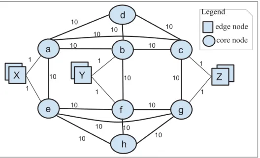
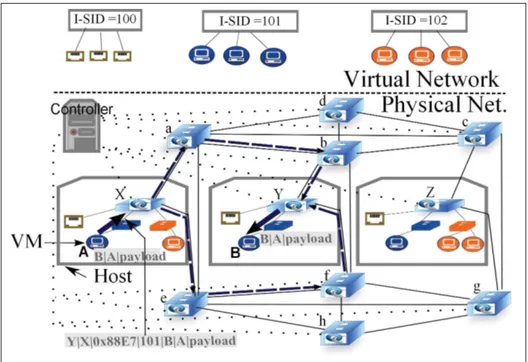
(37) 9. Figure 0.3. 0.2.1. Intra-DC, DCI and multi-layer carrier network. Multipath bandwidth aggregation in DCN. Figure 0.4 depicts the DCN topology: circles and squares, representing switch nodes and host nodes, are connected by links of various capacity weights (in Gbps). A multipath network is a network in which there is more than one path between any pair of nodes. For example, in Figure 0.4, the route linking nodes X and Y consists of multiple paths. The use of multiple paths simultaneously provides aggregated capacity, which is useful for applications that demand high bandwidth, such as virtual machine (VM) migration, eScience, and video. Aggregated capacity is the total capacity of all paths linking a pair of nodes. However, traditional forwarding mechanisms using a single path are not able to take advantage of available multiple physical paths. Moreover, a multitenant and highly dynamic virtualized environment consists of a large number of end-stations, leading to a very large number of flows that challenge the scalability in terms of address learning, forwarding state size, and forwarding decision convergence. For example, Ethernet address learning by flooding and remembering the ingress port restricts the.
(38) 10. topology to a cycle-free tree. In forwarding along a tree, switches near the root require more forwarding entries (TCAM).. Figure 0.4. Multipath topology example. Main issues are:. •. How to ensure per-flow aggregated capacity on multiple paths? How to allow a flow between nodes X and Y (Figure 0.4) to achieve the aggregated capacity of 2 Gbps along paths X-a-b-Y and X-e-f-Y? In the case of a failed (a, b) link, how the flow still achieves the aggregated capacity of 2 Gbps along the unequal paths X-e-f-Y and X-a-c-b-Y ? What is the solution for out-of-order delivery ?. •. How to achieve in-network multipath solution and network isolation for end-hosts in a multitenant dynamic virtualized environment?.
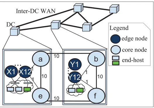
(39) 11. 0.2.2. Bandwidth reservation in DCI. Geographically distributed data centers are inter-connected through data center interconnect links. Figure 0.5 shows a DCI topology for 5 DCs, each of which has: i) two connected WAN-facing core nodes (e.g. a, e); ii) end-hosts connected to the edge nodes through intraDC connection; and iii) 12 edge nodes (e.g. X1-X12) connected to both core nodes that split traffic from the end-hosts over the core nodes. 5 DCs are inter-connected across their 10 WAN-facing core nodes.. Figure 0.5. The WAN-links between the data centers (DC) carry aggre-. DC level WAN topology and closer look at physical connectivity for a pair of DC. gated data traffic originating from within the co-located data producers. As stated in the Introduction, bandwidth reservation capabilities that dynamically provision network resources are recognized as extremely useful capabilities for many types of network services (Guok et al., 2006; Nadeau and Gray, 2013). Bandwidth reservation allocates and/or deallocates a certain amount of bandwidth that an activity is going to require either at a future time or immedi-.
(40) 12. ately (Nadeau and Gray, 2013). The existing approaches to in-advance reservation services provide limited reservation capabilities, e.g. limited connections over links returned by the traceroute over traditional IP-based networks. Main issues are:. •. The current reservation approaches/frameworks have a low acceptance rate of reservation requests even in the presence of available bandwidth, especially due to the limited number of forwarding rule supports in switches. The number of per-flow paths is too large to be handled by the switches.. •. How the affected reservation lookup can be made efficient to support fault tolerance in the event of node or link failures?. 0.2.3. Optimization in carrier network. The carrier network, that inter-connects geographically distributed data centers, itself consists of a multi-layered network. Figure 0.6 shows the IP/MPLS-over-OTN-over-DWDM Network in a vertical top-down order of 4 Customer-Edge IP (L3) routers (CE1-4) and 6 Provider/Provider-Edge MPLS (2.5) nodes (PE1-6) as IP/MPLS traffic demand layer, and 13 and 12 network nodes in the OTN (L1) and DWDM (L0) layers respectively. L0 nodes are connected by fiber links. Horizontal left-right order shows the network nodes’ placement as last mile/customer premise, access, metro or core network, divided by vertical lines. Each L0, L1 and L2.5 network node consists of boundary ports, i.e. trail termination points (TTPs) (each represented by a black circle:. ), and multiplexing ports, i.e. connection termination point. (CTP) pools (CTPPs) (each represented by a white circle: ). The TTP port connects to the CTPP port of the upper layer node. The link is called a boundary link (L0-L1, L1-L2.5 are not shown in Figure 5.2 for clarity’s sake, but should be understood as - ). PE5 and PE6 connect.
(41) 13. Figure 0.6. Multi-layered network and different routing mechanisms. to content distribution network (CDN) and Internet through Internet Exchange points (IXP). CEs are connected to the L2.5, L1 or L0 node, depending upon service demand. CEs’ interfaces with ≤1G are aggregated to 10G on the L2.5 node; and CEs’ interfaces with 10-40G are aggregated to the L1 node to take advantage of traffic grooming. CEs’ interfaces with 40-100G are directly connected to the L0 node. Service demands from the customer network elements CE1, CE2, CE3 and CE4 to the other CEs or PEs are served with 4 routes: LSP-1, LSP-2, LSP-3 and LSP-4, in which LSP-1 and LSP-2 go through MPLS/L2.5 switching as transit, LSP-3 bypasses MPLS/L2.5 switching with ODU/L1 switching, and LSP-4 goes directly over the OCh/L0 switching. On the basis of physical topology, the optimization algorithm computes logical links and the routing paths for all the service demands that can efficiently utilize the network’s resources. The lightpath for the L0 TTP-pair and the ODUpath for the L1 TTP-pair provides logical links in connected CTPP-pairs, and demand is then mapped onto a set of (logical) links. The result may be different sets of logical links for different sets of demands..
(42) 14. Main issues are:. •. How to design optimization model for IP/MPLS-over-OTN-over-DWDM network for traffic engineering ? The optimization needs to solve different technological aspects such as: three-layer traffic demands, non-uniform capacity types of Ethernet and OTUk ports, ODUflex’s flexible capacity and non-bifurcate capability of OTN and WDM switching layers.. 0.3. Outline of the thesis. Chapter 1 presents a review of state-of-the-art methods that are relevant to the scope of the research problems. Based on this literature review, the objectives of the research are defined, and the general methodology is proposed in Chapter 2. The three following chapters present the manuscripts written in response to specific research problematic. The manuscript defining our intra-DC multi-path is presented in Chapter 3. DCI reservation is described in Chapter 4. The multi-layer network optimization proposed is the subject of Chapter 5. Chapter 6 presents a global discussion, and finally, the work accomplished in the thesis is summarized in a general conclusion..
(43) CHAPTER 1 LITERATURE REVIEW This chapter presents a review of state-of-the-art methods related to the proposed traffic engineering on different administrative domains: DCN, DCI and multi-layer carrier network. This chapter is divided into four sections that are in line with the unified control and the three traffic engineering domain problems exposed in the introduction. The first section presents data center federation. The second section starts with a focus on multi-path in intra-DC networks. The third section covers methods specific to the reservation in DCI networks. Finally, the last section reviews optimization methods in a multi-layer carrier network.. 1.1. Data Center Federation. Data center federation is the practice of interconnecting the DC computing environments of two or more DC providers. It gives elasticity to VMs among DCs and thus, it is an enabler for load balancing and high availability services between DC providers. Different DCs normally consist of independent storage and network environments. If several DC environments can not inter-work, then the inter-DC virtual network can not be achieved for VMs. Any solution for inter-DC virtual network must maintain the insularity of the respective DCs in support of each DC’s IT infrastructure autonomy, privacy, and security requirements (Nagin et al., 2011). Autonomy refers to the ability of a DC to administer its IT infrastructure (for eg: network, storage topology reorganization, changing IP addressing schemes, use of any virtualization technology: VMWare, KVM or Xen) without consulting with other DCs. VM placement should only be motivated by a DC’s own internal policy. Security refers to the extent that an intruder can compromise a DC’s operations. A common security measure typically applied by organizations is to forbid access from outside the organization to its servers, except for those located in a specially designed “demilitarized zone (DMZ)”. Moreover, such servers are sometimes configured with non-routable IP addresses, and/or are hidden behind a NAT service. An example of possible security violation in the context of VM network is to require.
(44) 16. that the individual hosts have IP addresses directly accessible from the Internet. Privacy refers to the extent to which a DC must reveal the hardware and software used, DC topology and activity. Open source cloud platform like OpenStack (ope, 2017) is very promising for interoperability among DCs. As load balancing case, some load balancing VMs can be migrated offline, using export function of the cloud platform, to different DCs, while other online still serving the requests from current DC. The target DC places the VM live anywhere in its switching fabric and with tenant network identification of VM, provides a virtual network to those VMs running in the DC. The virtual network is stretched across DC sites. DC uses network overlay technologies to provide such virtual network and to be scalable to a large number of VMs. There are many network overlay technologies with different encapsulation frame formats including: Virtual Extensible LAN (VxLAN), Network Virtualization Using Generic Routing Encapsulation (NVGRE), Overlay Transport Virtualization (OTV), IEEE 802.1ad Provider Bridging, IEEE 802.1ah Provider Backbone Bridges, Transparent Interconnection of Lots of Links (TRILL), Location/Identifier Separation Protocol (LISP) and MPLS (cis, 2013). Host server or edge switch can support different tunneling functions. However, there is a non-trivial dependency on the control plane for address learning and for forwarding of Layer 2 broadcast, multicast, and unknown unicast traffic. For example, OTV (Cisco, 2012b) control plane (which uses ISIS) proactively advertises MAC reachability information, so that all OTV edge devices already know what MAC addresses are reachable via the overlay. The single control plane of an overlay technology across DCs violates DC isolation, as it exposes internal host servers for tunneling to other DCs. Even in case of internal migration inside the DC, it needs to coordinate to other DCs, obviously, it is an unnecessary burden. Moreover, there is no co-operation among the control planes of different overlay technologies to create stretched virtual network. Existing mobile IP solution (C. Perkins, 2002) for inter-domain VM mobility is not satisfactory, all traffic destined to a mobile VM has to go through an anchoring point - the mobile’s home agent. This triangular routing not only increases the packet delivery delay but also imposes a burden on the networks as well as the home agent. VICTOR (Hao et al., 2010) logically.
(45) 17. combine multiple geographically distributed physical devices with IP-in-IP tunnel and use a centralized controller to control the forwarding, eliminating the triangular problem. But this shares same controller among all DCs, updates about internal migration, and expose all internal routers, thus does not respect DC isolation. Recently control plane federation has favored the existence of multiple administrative network domains, that are controlled by individual SDN control plane. To setup end-to-end network with one user request, the control plane can follow any end-to-end setup coordination models: “star”, “daisy chain”, and hybrid star/daisy chain (Bobyshev et al., 2010). To achieve control plane federation with information exchange, the Internet engineering task force (IETF) developed a message exchange protocol, SDNi, as an interface between SDN controllers (Yin et al., 2012). Lin et al. proposed a west-east bridge to facilitate inter-SDN communication (Lin et al., 2015). With DC isolation in mind, in this thesis, we favor SDN approach with separate DC controllers and DCI controller, where data plane functions are simplified to tunneling and orchestrator coordinates between controllers to obtain reachability information and to stitch multiple segmentpaths.. 1.2. Multipath in DCN. The current Layer-3 (L3)-routed approach assigns IP addresses to hosts hierarchically, based on their directly connected switch. For example, hosts connected to the same Top of Rack (ToR) switch could be assigned the same /26 prefix, and hosts in the same row may have a /22 prefix (Cisco, 2013a). With such an assignment, the forwarding tables across all data center switches will be relatively small. So, using multiple L2-switched domains and an L3routed network for IP routing between them is a scalable addressing and forwarding solution. However, configuration and operational complexity are increased in the case of VM migration across L2 domains. VL2 (Greenberg et al., 2009) solves this problem and provides virtual L2 service in an L3-routed network by using IP-in-IP as the location separation mechanism and.
(46) 18. agent/directory service that follows end-system-based address resolution and takes advantage of a scalable L3 design. However, VL2 relies on ECMP, calculated by OSPF in L3 routers, which cannot use multiple paths for a flow. One of the challenges in L2-switched network deployments in current DCNs is that the spanning tree protocol (STP) will prune paths from the network to ensure a loop-free topology, resulting in a single-tree topology (Perlman, 2009). Moreover, STP effectively wastes much of the potential throughput between any pair of nodes (Perlman, 2009), and so a physical multipath design will not be fully exploited, which means that the DCN is not scalable. There is a growing interest to eliminate STP in L2 networks and enable multipath use in switching networks. There have been several improvements giving multiple STP instances, that is, multiple trees in a network. For example, Cisco’s Per-VLAN Spanning Tree (PVST) (Cisco, 2013b) creates a separate spanning tree for each VLAN in a multi-VLAN network, and the IEEE 802.1s MST (Multiple Spanning Tree) (IEEE Standard 802.1s, 2002) links multiple VLANs into a spanning tree, creating multiple trees in a network. The drawback of the multi-VLAN approach is resource fragmentation and under-utilization (Greenberg et al., 2008), because VM consolidation cannot be achieved between different VLANs. Link aggregation (IEEE 802.3ad) (IEEE Std 802.3ad-2000, 2000) combines multiple links to create a single logical connection between two directly connected endpoints and increases bandwidth. However, this solution does not deal with links traversing multiple switches. There are proprietary multi-chassis Etherchannel (MEC) solutions, VSS, vPC, and MLAG, for example, which allow link aggregation towards different switches to form a single logical switch, providing redundancy and resiliency (Cisco, 2013c; Arista). However, they are not yet supported by all the switches on the market. TRILL (Perlman, 2009) and SPB (IEEE Standard 802.1aq-2012, 2012) are emerging technologies as STP replacements. VL2 (Greenberg et al., 2009), TRILL (IETF RFC 5556) (Perlman, 2009), and SPB (Shortest Path Bridging IEEE 802.1aq-2012 (IEEE Standard 802.1aq2012, 2012)) use the Equal-Cost Multi-Path (ECMP) to spread traffic across multiple paths..
(47) 19. ECMP (Hopps, 2000) balances the load across flow-based paths by calculating a hash of every packet header, but uniquely mapping a flow to a single path to prevent out-of-order delivery at the destination. For example, a flow between nodes X and Y (Figure 0.4) can be mapped to either the X-a-b-Y or X-e-f-Y path. Thus, a single flow’s throughput is limited to single path capacity, not to the aggregated path capacity. Although there are many flows in a network, they are not always mapped to the right paths because of hashing collisions. The more links a flow traverses, the more collisions will occur (Al-Fares et al., 2010). With ECMP, the overall throughput is not optimal. Multipath network needs routing and load balancing to enable the use of the full bisection bandwidth. Techniques such as spanning trees, which are used in switched networks, are not applicable to recently proposed architectures (DCell (Guo et al., 2008), BCube (Guo et al., 2009), and Fat tree (Al-Fares et al., 2008)), because they do not exploit path diversity. Because DCN topologies contain numerous end-to-end paths for each pair of endpoints, traffic engineering can often improve the aggregate throughput by dynamically pinning flows to paths. Al-Fares et al. proposed a system for dynamic DCN traffic engineering called Hedera (AlFares et al., 2010) and showed that Hedera can improve network performance significantly. Hedera (Al-Fares et al., 2010) is a reactive flow scheduling technique designed to dynamically reroute flows on optimized paths. It performs load balancing by rescheduling flow on a single optimal path, but does not provide aggregated bandwidth. This technique also poses scalability issues on path convergence, and may result in path flapping in a congested network. Fat-treelike topologies can benefit from Valiant Load Balancing over ECMP (Greenberg et al., 2009) but even there, prior work has shown a gap of 20% from the optimal throughput (Benson et al., 2010). Bcube (Guo et al., 2009) routing considers link disjoint multipaths up to the number of interfaces of a server, as it is a symmetric topology with identical link capacity. In this paper, we consider asymmetric capacity links in the network and also compute intersecting paths..
Figure


+7

Documents relatifs
L'épaisseut aa de I'enrobage est supposée petite (Aala((l) devant les dimensions caractéristiques a de I'inclusion. La définition des propriétés effectives de l'élément
Les pustuloses néonatales amicrobiennes sont le plus souvent isolées et d’évolution favorable tel l’érythème toxique, la mélanose pustuleuse, la
The main motivation of the present paper can now be stated in simple terms: it is to provide a statistical model allowing one to analyze adaptive bandwidth allocation motivated by
In the simplest case where the network reduces to a single link of capacity C and a single class of traffic intensity ρ without limiting access rate, the corresponding model is
Unité de recherche INRIA Rennes : IRISA, Campus universitaire de Beaulieu - 35042 Rennes Cedex (France) Unité de recherche INRIA Rhône-Alpes : 655, avenue de l’Europe - 38334
Unité de recherche INRIA Rennes : IRISA, Campus universitaire de Beaulieu - 35042 Rennes Cedex (France) Unité de recherche INRIA Rhône-Alpes : 655, avenue de l’Europe -
Our work deals with the energy consumption issue in dedicated network with bandwidth provisionning and in-advance reservations of network equipments and bandwidth for Bulk
The OTF allocation algorithm uses a set of three parameters for each of the mote’s neighbors: (i) S, the number of currently scheduled cells; (ii) R, the number of cells required
