UV radiation effects on Liquid Crystal Variable Retarders for aerospace
applications
Pilar García Parejo1,*, Alberto Álvarez-Herrero1, Néstor Uribe-Patarroyo1, Raquel López Heredero1, René Restrepo1, Marc Georges2
1 Laboratorio de Instrumentación Espacial (LINES), Instituto Nacional de Técnica Aeroespacial (INTA), Ctra. Ajalvir km4, Torrejón de Ardoz, E-28850, Madrid, Spain.
2 Centre Spatial de Liège-Université de Liège, Liege Science Park, Avenue du Pré-Aily, 4031 Angleur, Belgium;
INTRODUCTION
Liquid-Crystal Variable Retarders (LCVRs)1 are optical devices that provide a variable optical retardance accomplished by the application of electric fields. Traditionally, they have been used as light polarization modulators for polarimetric applications in ground telescopes2, and more recently they took part in the polarisation modulation package of the Imaging Magnetograph eXperiment (IMaX)3, where the LCVRs were launched successfully on-board the Sunrise mission, a stratospheric balloon that was flown from the Arctic (Kiruna, Sweden) to study the solar magnetic fields. IMaX was the precursor of the Solar Orbiter mission4 of the European Space Agency (ESA), where the liquid crystals will be used as polarisation modulators onboard a space mission for the first time in two instruments: the Polarimetric and Helioseismic Imager (SO/PHI) and the Multi-Element Telescope for Imaging and Spectroscopy (METIS).
Any onboard element used for aerospace applications must be able to survive the harsh environmental space conditions including UV radiation, gamma radiation, vibrational tests, thermal-vacuum... In this sense, LCVRs have been recently validated to be used under the space conditions of the Solar Orbiter mission, in the framework of the ESA project5 with contract reference: 22334-09-NL-SFe, “Validation of LCVRs for the Solar Orbiter Polarisation Modulation Package”. In this project, a set of LCVRs with different design parameters has been analyzed under the different space environmental conditions. These design parameters include the architecture of the LCVR cell, using Anti-Parallel Aligned Nematic (APAN) and Hybrid Aligned Nematic (HAN) architectures, the type of liquid crystal molecules, using different commercial nematic liquid crystal mixtures with high and low birefringence and positive and negative dielectric anisotropy, different homogeneous and homeotropic polyimide alignment layers and different glass plates.
Among the space environmental components, the UV radiation needs special consideration due to the organic nature of the liquid crystal molecules and the alignment layers that consisted of rubbed polyimide layers. In this work, we present the preliminary results of the UV radiation test campaign carried out in the LCVRs, consisting of the performance of a thorough optical characterization of the LCVRs, including optical retardance and response times measurements at different voltages performed by the ellipsometry technique, and optical transmission measurements, before and after irradiating the LCVRs with UV light at different doses, in two different spectral ranges: 200 -400 nm and 160-200 nm. EXPERIMENTAL
The set of LCVR cells analyzed consisted of six types of LCVR cells, selecting two types of cell geometry: Anti-parallel Aligned Nematic (APAN) and Hybrid Aligned Nematic (HAN).
In APAN geometry both glass plates are coated with homogeneous alignments in anti-parallel direction that forces the molecules to align their longitudinal axis parallel with respect to the glass plates exhibiting maximum anisotropy for a normal incident light when no voltage is applied. This geometry uses liquid crystal mixtures with positive dielectric anisotropy and as the voltage is applied, the electric field exerts a torque that forces the molecules to align parallel to the electric field, causing the reduction of the optical anisotropy shown by the cell. Four commercial liquid crystal mixtures from Merck with different birefringence: ZLI-3700-000, MLC-6025-000, BL006 and MDA-98-1602 and two types of rubbed homogeneous polyimide alignment layers: PI2545 and PIA2000 were used. Two types of glass substrates were also tested: fused silica and SF57 in order to verify their UV screening effect upon the liquid crystal molecules.
In HAN geometry one of the glass plates shows homogeneous alignment and the other homeotropic alignment. The homeotropic alignment aligns the LC molecules perpendicularly to the glass plates. Therefore, when no voltage is applied in the vicinity of the homogeneous alignment, the molecules are orientated parallel to the glass plates, and the closer they are from the homeotropic layer, the more perpendicular they will be to the glass plates. A liquid crystal mixture with negative dielectric anisotropy was used in this case: MLC-6610, which means that the molecules will align perpendicularly to the electric field (i.e. parallel to the glass substrates) as the voltage applied is increased, exposing higher anisotropy to normal incident light.
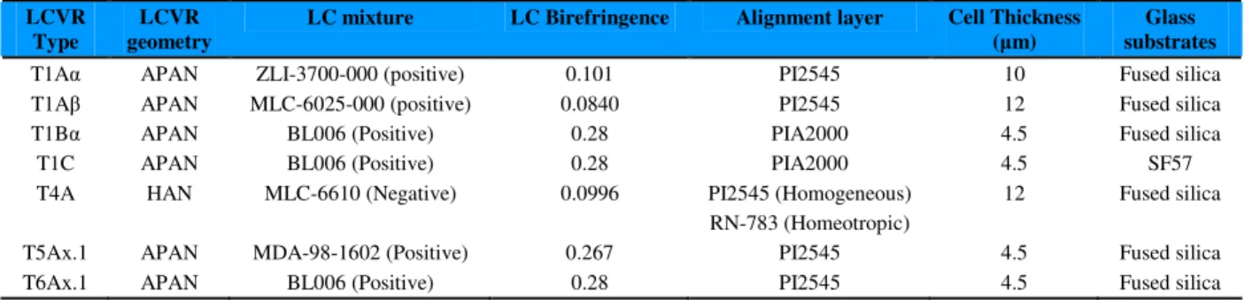
The thickness of the cell was selected to have a total optical retardance range higher than 1λ at 617.3 nm in order to fulfil with the scientific requirements of the SO/PHI instrument for the Solar Orbiter mission. A summary of the components used for the set of the different LCVRs cells is shown in Table 1.
LCVR Type
LCVR geometry
LC mixture LC Birefringence Alignment layer Cell Thickness (µm)
Glass substrates
T1Aα APAN ZLI-3700-000 (positive) 0.101 PI2545 10 Fused silica
T1Aβ APAN MLC-6025-000 (positive) 0.0840 PI2545 12 Fused silica
T1Bα APAN BL006 (Positive) 0.28 PIA2000 4.5 Fused silica
T1C APAN BL006 (Positive) 0.28 PIA2000 4.5 SF57
T4A HAN MLC-6610 (Negative) 0.0996 PI2545 (Homogeneous)
RN-783 (Homeotropic)
12 Fused silica
T5Ax.1 APAN MDA-98-1602 (Positive) 0.267 PI2545 4.5 Fused silica
T6Ax.1 APAN BL006 (Positive) 0.28 PI2545 4.5 Fused silica
Table 1. Summary of the components used
A thorough optical characterisation of the LCVRs consisting of the measurement of the optical retardance and the response times at different voltages, using the null ellipsometry technique6, and optical transmission measurements for the s and p polarisations was performed before and after the UV test campaign. The optical retardance and response times of the LCVRs were measured at a constant temperature of 40ºC.
The UV radiation test campaign was carried out in the facilities of the Centre Spatial of Liege, irradiating three cells per LCVR type at the estimated UV doses expected throughout the Solar Orbiter mission and taking into account the transmittance of all the filters and optical elements along the optical path before reaching the LCVRs. All the cells were irradiated with UV light in the spectral range of 200-400 nm during the total dose of 1.50 ESH (Equivalent Solar Hour). 1.00 ESH is the radiation of the Sun during one hour at 1 A.U taking into account the Solar Constant according to AST E-490 standard7.Therefore, for the given spectral range of 200-400 nm, 1.00 ESH is equivalent to irradiate with 105.7 W/m2 during 1 hour. One of these three cells was studied more thoroughly and measured at several intermediate doses (0.25 ESH, 0.50 ESH, 1.00 ESH and 1.5 ESH) in the spectral range of 200-400 nm and irradiated with UV light in the spectral range of 160-200 nm during a total dose of 1.00 ESH. In the spectral range of 160-200 nm, 1.00 ESH is equivalent to irradiate with 0.09 W/m2 during 1 hour.
RESULTS
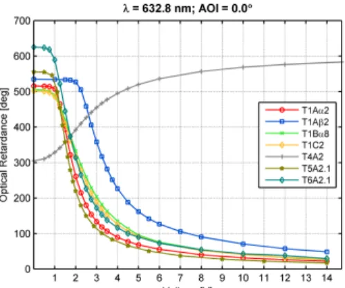
All the LCVR cells were characterised before performing the UV radiation campaign. The optical retardance measurements vs. voltage for one of each type of the LCVR cells are shown in Figure 1. Cells with APAN geometry decrease their optical retardance as voltage is applied due to the reduction of the anisotropy exhibited by the molecules to normal incident light. The cell type T4A shows different behaviour with regard to the rest of the cells due to this geometry uses a liquid crystal mixture with negative dielectric anisotropy and therefore, the molecules tend to align perpendicular to the external electric field applied, exhibiting a higher anisotropy and therefore higher optical retardance.
On the whole, the irradiation with UV light in the spectral range of 200-400 nm causes the reduction of the optical retardance range, which involves a reduction in the anisotropy of the LCVRs cells, as shown in Figure 2 and Figure 3. A decrease in the anisotropy of the cells can be attributed to the reduction of the birefringence of the liquid crystal molecules because of the modifications in its chemical structure or the degradation of the alignment layers that produces an increase of the pretilt angle8. An increase of the response times of the LCVR cells was also observed due probably to an increase of the visco-elastic coefficient (γ1/K11), effect that was observed in other studies in the literature8.
Figure 1. Optical retardance vs. voltage of the LCVR cells.
Figure 2. Type T1Aα. In the left, optical retardance vs voltage after different UV doses. In the right, response times of two transitions after different UV doses.
Figure 3. Type T4A. In the left, optical retardance vs voltage after different UV doses. In the right, response times of two transitions after different UV doses.
The irradiation with UV light in the range of 160-200 nm did not cause any significant change in the LCVR cells except for the Hybrid Aligned Nematic cell, the T4A type. In this case, we observed an increase of the optical retardance range. As an increase of the birefringence of the molecules is unlikely, we suppose that this can be due to changes in the alignment of the molecules along the cell due to the degradation of the homeotropic or homogeneous alignment layer. A decrease of the response time of the cell was found in this case. Further studies about these issues are currently in progress
The liquid crystal mixture BL006 showed a very high photo-stability under UV radiation, as cells containing the liquid crystal mixture BL006 (T1Bα, T1C and T6Ax.1) did not show significant changes in the optical retardance or the response times, becoming the liquid crystal mixture BL006 in a very good candidate for the definitive LCVRs that will be used in the Solar Orbiter mission. No significant differences either were found between the LCVR cells that use the polyimide homogeneous layers PIA2000 or PI2545 if we compare T1Bα and T6Ax.1. Therefore both alignment layers are also promising components for the mission.
No systematic behaviour was found in the photo-stability of the LC molecules with high or low birefringence. Most of the studies found in the literature were carried out using lamps at 365 nm as this is the typical wavelength used for sealing the LC panels. High birefringence liquid crystal molecules show absorption peaks at longer wavelengths due to their longer conjugation length8 and therefore they usually are less stable under UV radiation due to they show more absorption at 365 nm. Nevertheless as our study was performed in a wider spectral range in the UV, the specific molecular structure of the liquid crystal molecules play a more important role in the stability of the molecules under UV radiation. This must be the case for the LC mixtures BL006 and MDA-98-1602 that with a similar birefringence, they showed a very different photo-stability under UV, being BL006 quite more photo-stable.
CONCLUSIONS
A set of Liquid Crystal Variable Retarders has been studied under UV radiation in order to validate this technology for being used for the first time as polarisation modulators on board a space mission: the Solar Orbiter mission.
Different configurations of LCVRs have been characterised and analyzed under UV radiation in two different spectral ranges: 160-200 nm and 200-400 nm. As a whole a decrease of the optical retardance range for all the LCVR cells was found after UV irradiation in the spectral range of 200-400 nm pointing out a decrease in the birefringence of the molecules or the increase of the pretilt angle, except for cells that use the liquid crystal mixture BL006 that showed a very high photo-stability under UV radiation. An increase of the response time of the LCVR cells was also found. No significant changes were observed in the APAN cells irradiated in the spectral range of 160-200 nm. Nevertheless, HAN cells (T4A) showed a different behaviour in that spectral range as an increase of the optical retardance range was observed pointing out to changes in the alignment of the molecules along the cell.
Nevertheless, in all the cases, the degradation effects observed do not involve the destruction of the liquid crystal cells and most of them keep fulfilling the requirements for the Solar Orbiter mission becoming LCVRs in a promising technology for aerospace applications.
ACKNOWLEDGES
The authors gratefully acknowledge the financial support provided to this research by the MICINN (Ministerio de Ciencia e Innovación), projects AYA2009-14105-C06-01 and AYA2011-29833-C06-01.
[1] R. L. Heredero, N. Uribe-Patarroyo, T. Belenguer, G.Ramos, A. Sánchez, M. Reina, V. Martínez Pillet and A. Álvarez-Herrero, Liquid-crystal variable retarders for aerospace polarimetry applications, Appl. Opt. {46}, 689 (2007).
[2] T. Horn and A. Hofmann, Liquid Crystal Imaging Stokes Polarimeter, Third Advances Solar Physics Euro conference: Magnetic Fields and Oscillations, ASP Conference Series {184}, 33 (1999).
[3] N. Uribe-Patarroyo, A. Álvarez-Herrero, R. L. Heredero, J. C. del Toro Iniesta, A. C. López Jiménez, V. Domingo, J. L. Gasent, L. Jochum, V. Martínez Pillet and the IMaX Team, IMaX: a polarimeter based on Liquid Crystal Variable Retarders for an aerospace mission. Phys. Stat. Sol (c) {5}, 1041 (2008).
[4] http://sci.esa.int/solarorbiter
[5] A. Alvarez-Herrero et al. Imaging polarimeters based on Liquid Crystal Variable Retarders: an
emergent technology for space instrumentation. Polarization Science and Remote Sensing V,
Proceedings of SPIE, {8160}, (2011)
[6] Azzam & Bashara, “Ellipsometry and polarized light”, North-Holland Personal Library Elsevier
Amsterdam 2003.
[7] “Standard Solar Constant and Zero Air Mass Solar Spectral Irradiance Tables”, ref. ASTM E-490_00a, 2006.
[8] Chien-Hui Wen, S. Gauza and Shin-Tson Wu, Photostability of liquid crystals and Alignment layers,
Journal of the SID, 13/9 (2005).
_____________________________________________