Université du Québec
Institut national de la recherche scientifique INRS-Énergie Matériaux et Télécommunications
Millimeter-wave Electromagnetic Band-gap Structures for
Antenna and Antenna Arrays Applications
by
Mu’ath J. Al-Hassan
A dissertation submitted in partial fulfillment of the requirements
for the degree of Doctor of Philosophy (Ph.D.) in Telecommunication Engineering
Evaluation Jury
External examiner Prof. Chan-Wang Park
Université de Québec à Rimouski (UQAR)
External examiner Prof. Khelifa Hettak
Communication Research Center Canada (CRC)
Internal examiner Prof. Serioja Ovidiu Tatu
INRS-Énergie Matériaux et Télécommunications
Research co-director Prof. Abdel Razik Sebak Concordia University
Research director Prof. Tayeb A. Denidni
INRS-Énergie Matériaux et Télécommunications
ABSTRACT
Recently, communication systems and applications have been driven toward the millimeter-wave band (MMW). In addition to the emerging demands of compact, high-speed, and large bandwidth systems, the crowd of RF bands, and the commercial availability of MMW components have made the MMW band a suitable choice for many short-range wireless applications. Moreover, compared to the ultra-wide band (UWB), MMW bands are free of major interference sources that UWB systems may suffer from.
However, and from antenna designers’ point of view, MMW bands suffer from the high attenuation characteristics associated with these bands. Therefore, researchers have proposed several techniques to overcome this problem. Nevertheless, most of these techniques have proven major drawbacks that negatively affect the antenna performance.
Furthermore, and due to the compact sizes of the circuits and components at the MMW bands, the mutual coupling between antenna array elements has becomes a big concern that deteriorates the efficiency of the communications systems, especially in multiple-input-multiple output (MIMO) systems, where it has been proven that mutual coupling strongly affects the systems capacity.
Therefore, the main research in this thesis work consists of several investigations and techniques on increasing the gain and improving the radiation characteristics of complex-structured MMW antennas by using Electromagnetic Band-Gap (EBG) structures. Experimental results show the advantages of these techniques over those exist in the literature.
Moreover, the applications of Mutual-coupling reduction in Antenna arrays at MMW wave bands new compact EBG unit-cell is introduce in this work. It has been proven to effectively reduce the mutual coupling between antenna array elements at MMW bands.
Reconfigurable radiation pattern antennas are in the scope of this work. Their ability to meet the demands of emerging communication systems and applications by producing diversity in radiation pattern, polarization, and frequency made them very attractive to be used in the MMW bands.
To my parents; Rima and Jodei; To my brothers Moayyad & Mohammed, and my sisters Ruba & Rahaf.
ACKNOWLEDGMENT
First and foremost, I would like to express my deepest gratitude to my supervisor, Prof. Tayeb A. Denidni who has been a tremendous mentor for me. I really appreciate his continues support, aspiring guidance, invaluably constructive criticism, and immense knowledge. I would like to thank you for encouraging my research and allowing me to grow up as a researcher.
Beside my supervisor, I would like to acknowledge with much appreciation my co-supervisor Prof. Abdel Razik Sebak. He continually and persuasively helped me in all the time of research and writing this thesis.
In addition, I would like to thank the rest of my committee: Prof. Chan-Wang Park, Prof. Khelifa Hettak, and Prof. Serioja Ovidiu Tatu for their encouragements, insight comments and suggestions. I also want to thank you for letting my defense be an enjoyable moment.
Special thanks to my family. Words cannot express how grateful I am to my mom, father, brothers and sisters for all the sacrifices that you have made on my behalf. Your prayers for me were what sustained me thus far.
Last but not the least, my sincere thanks go to my colleagues for our constructive discussions, exchanges of knowledge and venting of frustration during my PhD program.
Finally special thanks to those who helped me in developing this thesis.
Table of Contents
Abstract I Acknowledgment II List of Figures III List of Tables VIII
ABSTRACT ... I RESUME ... IX Motivations ... IX Problèmes et Objectifs de Recherche ... X Contribution des travaux de thèse ... XVI Organisation de la thèse ... XVII References ... XVIII
CHAPTER ONE: INTRODUCTION ... 1
1.1 Motivations ... 1
1.2 Research Problem and Objectives ... 2
1.3 Thesis Contribution ... 7
1.4 Thesis Organization ... 8
CHAPTER TWO: MILLIMETER-WAVE APERTURE-COUPLED DIELECTRIC RESONATOR ANTENNA BACKED WITH ARTIFICIAL MAGNETIC
CONDUCTOR SURFACE ... 13
2.1 Introduction ... 13
2.2 The proposed Artificial Magnetic Conductor Unit Cell ... 14
a) TE polarization...14
b) TM polarization ...15
2.3 Reflection Phase Characteristics of the Proposed AMC Surface ... 19
2.4 Antenna Geometry ... 23
2.5 Experimental Results ... 29
2.6 References ... 37
CHAPTER THREE: MMW EBG-BASED APERTURE COUPLED DIELECTRIC RESONATOR ANTENNA ... 39
3.1 Introduction ... 39
3.2 Circular patch (CP)-EBG Design and Characteristics ... 40
EBG-unit cell ... 40
3.3 MMW EBG-Based Aperture Coupled Dielectric Resonator Antenna ... 44
Antenna Geometry ... 44
3.4 Experimental Results ... 46
a) S-Parameters ...46
b) Radiation Patterns and Antenna Gain ...48
3.5 References ... 52
CHAPTER FOUR: MUTUAL COUPLING REDUCTION IN MILLIMETER-WAVE DIELECTRIC RESONATOR ANTENNA ARRAYS USING NEW COMPACT ELECTROMAGNETIC BAND-GAP STRUCTURE ... 55
4.1 Introduction ... 55
4.2 EBG Unit Cell Design ... 56
4.3 MMW EBG-based Dielectric Resonator Antenna Array ... 62
4.4 Experimental Results ... 64
CHAPTER FIVE: NEW MILLIMETER-WAVE HYBRID ISOLATOR FOR
MUTUAL-COUPLING REDUCTION IN ANTENNA ARRAYS ... 73
5.1 Introduction ... 73
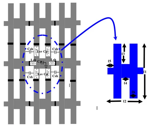
5.2 Proposed Hybrid structure ... 74
a) Proposed EBG Unit-Cell ...75
b) MMW Choke Absorber ...78
5.3 Validation and experimental results ... 79
Antenna Array Design ... 79
5.4 References ... 86
CHAPTER SIX: MILLIMETER-WAVE EBG-BASED DIELECTRIC RESONATOR ANTENNA WITH RECONFIGURABLE RADIATION PATTERN ... 88
6.1 Introduction ... 88
6.2 EBG Design and Switching Configuration ... 89
a) EBG Structure Design ...89
b) Diode Characterization ...90
a) Biasing Circuit ...91
6.3 Antenna Design ... 95
6.4 Results and discussions ... 97
6.5 References ... 100
CHPATER SEVEN: CONCLUSION AND FUTURE WORK ... 101
7.1 Conclusion ... 101
7.2 Future works ... 104
List of Figures
Fig.2-1. Geomtry of the proposed AMC structure... 14
Fig 2-2. Photograph of the fabricated AMC. ... 18
Fig.2-3. Reflection phase measurement set up. ... 18
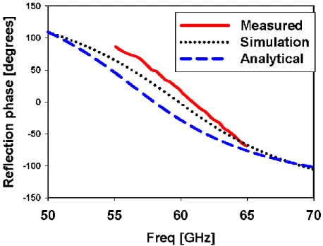
Fig.2-4. Proposed AMC reflection phase of normal incidence. ... 20
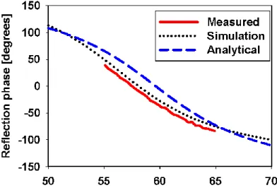
Fig.2-5. Proposed AMC reflection phase of TM polarized plane wave with 30o angle of incidence. ... 20
Fig. 2-6. Proposed AMC reflection phase of TM polarized plane wave with 60o angle of incidence. ... 21
Fig. 2-7. Proposed AMC reflection phase of TE polarized plane wave with 30o angle of incidence. ... 21
Fig.2-8. Proposed AMC reflection phase of TE polarized plane wave with 60o angle of incidence. ... 22
Fig.2-9. Exploded view of the proposed antenna. ... 24
Fig.2-10. Equivalent image of a horizontal magnetic current above a PEC surface (left) and PMC surface (right). ... 25
Fig.2-11. Simulated H-plane power patterns at 60 GHz of the PEC-backed antenna for different values of s. ... 26
Fig.2-12. Simulated H-plane power patterns at 60 GHz of the proposed antenna for different values of s. ... 27
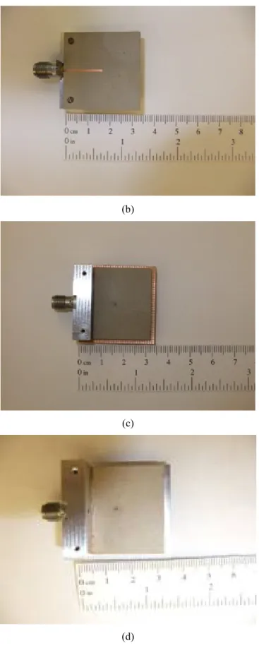
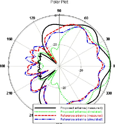
Fig. 2-13. Photos of the fabricated antenna prototypes. (a) Reference antenna (top view) (b) Reference antenna (bottom view) (c) Proposed antenna (top view) (d) PEC-backed antenna (top view). ... 30 Fig.2-14. Simulated and measured reflection coefficients of the reference, PEC-backed, and proposed antennas. ... 31 Fig.2-15. Simulated and measured normalized H-plane power patterns at 60 GHz of the reference and proposed antennas. ... 33 Fig. 2-16. Simulated and measured normalized E-plane power patterns at 60 GHz of the reference and proposed antenna. ... 34 Fig.2-17. Simulated and measured normalized H-plane power patterns at 60 GHz of the reference and PEC-backed antenna. ... 34 Fig.2-18. Simulated and measured normalized E-plane power patterns at 60 GHz of the reference and PEC-backed antennas. ... 35 Fig.2- 19. Simulated and measured gain as function of frequency of the reference, proposed, and PEC-backed antennas ... 36 Fig.3-1. The proposed EBG structure. (a) Geometry of the structure. (b)
Microscopic photo of the proposed EBG unit cell. ... 41 Fig.3-2. Dispersion diagram of the proposed CP-EBG. ... 42 Fig.3-3. Photo of the measured asymmetric microstrip line structure. ... 43 Fig.3- 4. Simulated and measured transmission coefficients of the asymmetric microstrip line structure shown in Fig.3-3. ... 43 Fig.3-5. Exploded view of the proposed antenna. ... 45 Fig.3-6 Simulated reflection coefficientsand maximum gain for different values of S ... 46 Fig. 3-7. Photos of the fabricated antenna prototypes. (a) Reference antenna (b) Proposed antenna ... 47 Fig.3-8. Simulated and measured reflection coefficients of the reference, and
proposed antennas. ... 48 Fig.3-9. Simulated and measured normalized H-plane power patterns at 60 GHz of the reference and proposed antennas. ... 49
Fig.3-10. Simulated and measured normalized E--plane power patterns at 60 GHz of the reference and proposed antennas ... 50 Fig.3-11. Simulated normalized H- and E--plane power patterns at 57 GHz and 63 GHz of the proposed antenna. ... 50 Fig.3-12. Simulated and measured maximum gain as function of frequency of the reference and proposed antennas. ... 51 Fig.3-13. Simulated electric field distribution in the surface of the EBG plane, (a) without EBG, (b) with EBG (right). ... 52 Fig.4-2. Geometry of the proposed EBG unit-cell. ... 57 Fig.4-3. Dispersion diagram of the proposed EBG in the OX direction... 59 Fig.4-4. (a)The fabricated symmetric microstrip line structure. (b) Reference
structure. (c) Zoomed view of the proposed EBG structure. ... 60 Fig.4-5. Simulated and measured transmission coefficients of proposed EBG
structure. ... 61 Fig.4-6. The proposed antenna array: exploded view (top), side view (bottom). ... 63 Fig.4-7. Photos of the fabricated antenna array prototypes: (a) proposed array, (b) reference array, and (c) bottom view of the proposed/ reference array. ... 65 Fig.4-8. Simulated and measured transmission coefficients of the proposed and reference antenna arrays. ... 67 Fig.4-9. Simulated and measured reflection coefficients of the proposed and
reference antenna arrays. ... 67 Fig.4-10. (a): Volume current distribution inside the two DR antennas at 60 GHz (XZ plane). (b) Surface current distribution on the EBG structure at 60 GHz (XY plane). ... 68 Fig.4-11. Measured normalized E- and H-plane power patterns at 60 GHz of the proposed and reference antenna arrays. ... 69 Fig.4-12. Measured and calculated maximum gain of the proposed antenna array. ... 70 Fig.5-1. Geometry of the conventional (left) and proposed (middle) EBG unit-cells, macroscopic photo of the fabricated EBG structure (right). ... 75
Fig.5-2. The fabricated symmetric microstrip line structure. ... 76 Fig.5-3. Transmission coefficients of the proposed and conventional EBG
structures. ... 77 Fig.5-4. Dispersion diagram of the proposed EBG in the OX direction... 77 Fig.5-5. (a) The MS-760KW absorber , and (b) the absorption performance from the data sheet. ... 79 Fig.5-6. Geometry of the proposed antenna array; perspective view (top), and side view (bottom). ... 80 Fig.5-7. Photographs of the fabricated antenna array prototypes: (a) reference array, (b) array with EBG isolator, and (c) array with the proposed hybrid isolator. ... 82 Fig.5-8. Simulated and measured reflection coefficients of the proposed and
reference antenna arrays. ... 83 Fig.5-9. Simulated and measured transmission coefficients of the proposed and reference antenna arrays. ... 83 Fig.5-10. Normalized E- plane power patterns of an individual DR antenna for different isolation techniques. ... 85 Fig.5-11. Normalized H- plane power patterns of an individual DR antenna for different isolation techniques. ... 85 Fig.6-1. Exploded view of the proposed EBG structure. ... 90 Fig.6-2. Measurement set-up. ... 91 Fig.6-3. Reflection and transmission characteristics of the proposed EBG structure. ... 92 Fig.6-4. Biasing circuit of the proposed EBG structure. ... 93 Fig.6-5. Layout of the proposed biasing circuit ... 93 Fig.6-6. Layout of the biasing circuit with a butterfly stub added after the diode. . 94 Fig.6-7. Photo of the fabricated EBG structure with the biasing circuit ... 94 Fig.6-8. Measured Transmission characteristics of the proposed EBG structure. .. 95 Fig.6-9. Photograph of the fabricated antenna structure ... 102 Fig.6-10. Measured reflection coefficient of the proposed (with EBG) and reference (without EBG) antennas ... 103
Fig.6-11. Measured radiation pattern in the azimuth planewhen diode 4,5: ON ... 98 Fig.6-12. Measured radiation pattern in the azimuth planewhen diode 1,2: ON ... 99 Fig.6-13. Measured radiation pattern in the azimuth planewhen diode 1,5,6: ON .. 99 Fig.6-14. Measured radiation pattern in the azimuth planewhen diode 2,3,4: ON 100
List of Tables
Table 2-1 AMC reflection phase of a TM polarized plane-wave. ... 22
Table 2-2 AMC reflection phase of a TE polarized plane-wave. ... 22
Table 4-1 Proposed EBG Unit-cell dimensions ... 57
Table 4-2 Dimensions of the proposed and conventional EBG unit-cells ... 58
Table 5-1 Proposed EBG Unit-cell dimensions ... 75
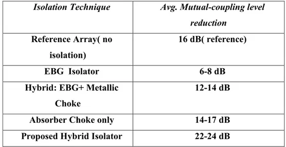
Table 5-2 Summary of the transmission coefficients for different isolation techniques. ... 84
RESUME
Ce chapitre résume les travaux de recherche effectués dans le cadre de ma thèse en commençant par présenter les motivations de mon projet de recherche. Ensuite, les problèmes et les objectifs des travaux sont identifiés avec des solutions proposées et discutées. Puis, les contributions du projet sont présentées. Enfin, les grandes lignes du projet de recherche sont établies.
Motivations
Les bandes millimétriques (MMW) ont attiré beaucoup l’attention des chercheurs au cours des dernières années. D’ailleurs ils ont un grand potentiel pour répondre aux besoins émergents des systèmes de communication sans fil. À part de la communication à grande vitesse et la largeur de bande, les systèmes de communication sans fil dans la bande des 60 GHz permettent l'intégration des antennes compactes et à haut rendement. Ces attributs font d la bande 60 GHz un choix approprié pour de nombreux applications sans fil à courte portée.
Selon une étude récente [2], les communications à 60 GHz présentent plusieurs avantages par rapport aux communications UWB:
- La coordination internationale pour les spectres de fréquences est difficile pour l'exploitation UWB par rapport aux communications à 60 GHz.
- Les systèmes UWB peuvent causer des interférences pour les systèmes WLANs à 2,4 GHz et 5 GHz (bandes sans licence), tandis que les bandes à 60 GHz sont libres des principales sources d'interférence.
- Pendant que les systèmes UWB peuvent fournir des débits de données jusqu'à 480 Mbps, les appareils à 60 GHz sont capables de fournir des débits de l'ordre de plusieurs Gbps.
puissance du signal reçu peut montrer beaucoup plus de variations dans le spectre de signaux UWB (où le spectre peut varier entre 3,1 GHz et 10,6 GHz), tandis que la gamme dynamique de perte du trajet sur les fréquences à 60 GHz est considérablement plus faible.
Cependant, certains obstacles se dressent dans l’application commerciale des bandes MMW. Les fortes pertes de conducteur des bandes MMW détériorent l'efficacité de radiation des antennes métalliques classiques. Un autre obstacle auquel fait face l’application des bandes MMW est la caractéristique d'atténuation élevée. Étant donné que la longueur d'onde de la bande à 60 GHz se trouve au voisinage de 5 mm, on peut s'attendre à un taux élevé d'atténuation due aux pertes sur le trajet. En outre, aux bandes MMW, l’atténuation due à l'absorption des molécules d'oxygène est importante.
En passant à des réseaux d'antennes opérant dans bandes MMW, le couplage mutuel entre les éléments rayonnants dans les réseaux devient sévère en raison de la compacité des systèmes. Le couplage mutuel a des effets négatifs sur la capacité et l'efficacité des systèmes de communications en ondes millimétriques.
Dans ce contexte, on propose dans cette thèse plusieurs solutions originales pour surmonter les difficultés dans les systèmes de communication en ondes millimétriques.
Problèmes et Objectifs de Recherche
Plusieurs techniques ont été proposées afin d'augmenter le gain d'une antenne et réduire les lobes secondaires. Parmi ces techniques, on peut citer l'utilisation d'un conducteur électrique parfait (PEC) en tant que support réflecteur pour minimiser le niveau du lobe arrière et accroitre le gain [3-7]. Habituellement, le réflecteur PEC est placé à un quart de la longueur d'onde guidée par rapport à l'antenne source. Dans une antenne, combiner une couche à fente avec un réflecteur PEC forme un guide d'onde. Ceci provoque une fuite d'énergie entre les plaques parallèles; par conséquent l'apparition des lobes secondaires et la dégradation du rendement de l'antenne [5-8]. En
outre, une couche arrière de support avec des cavités métalliques fermées [9] ou l'insertion des broches autour de l'ouverture [10] sont considérées comme des techniques conventionnelles afin de réduire le lobe arrière et augmenter le gain de l'antenne. Cependant, ces techniques constituent un véritable défi en bandes millimétriques à cause de la complexité de fabrication et à la réduction de la largeur de bande à travers les résonances qui peuvent en survenir [3].
Pour faire face à ces problèmes, une nouvelle approche scientifique s'est dirigée vers l’utilisation des matériaux à base de surface à haute impédance HIS (High Impédance Surface) [11]. Les HIS sont des matériaux composites artificiels qui présentent de nouvelles et uniques caractéristiques qui ne sont pas réalisables à partir de matériaux conventionnels. Ils sont généralement formés par des motifs métalliques périodiques, comme un réseau de patch ou de ruban, imprimés sur des substrats diélectriques. Plus spécifiquement, les matériaux à bande interdite électromagnétique (BIE) forment un sous-ensemble des matériaux HIS. Ils ont la propriété de contrôler la propagation des ondes électromagnétiques. Ces structures peuvent jouer un rôle de filtre fréquentiel et de filtre spatial [3]. Ces caractéristiques ont permis l’utilisation des matériaux BIE dans la conception d'antennes avec une bonne efficacité, un gain plus élevé et des lobes secondaires réduites [12, 13]. Les BIE sont également connues d'avoir une bande de fréquence dans laquelle une onde plane incidente est réfléchie avec une phase de réflexion égale à zéro degré [8, 14-18].
Cette caractéristique unique permet aux BIE d’avoir un comportement similaire à un conducteur magnétique parfait (CMP) sur une bande de fréquence limitée [8]. Les CMP, qui n’existent pas dans la nature, possèdent trois caractéristiques intéressantes. Premièrement, les courants d'image sont en phase avec ceux d'origine; par conséquent, ils peuvent remplacer les réflecteurs PEC et améliorer l'efficacité de l'antenne dans le champ lointain [8]. Deuxièmement, dans le cas où ils sont utilisés comme des réflecteurs, les modes de plaques parallèles d'ordres supérieurs peuvent être supprimés en choisissant la bonne distance entre l'antenne et le CMP, tout en gardant le mode dominant non affecté
surface en fournissant une haute impédance de surface équivalente, et par conséquent, ils améliorent le rayonnement de l'antenne et réduisent les effets de diffusion de bord [8]. La réalisation physique d'un CMP sur une bande de fréquence finie est connue comme conducteur magnétique artificiel (CMA) [20]. Les CMA ont récemment eu une énorme attention dans la littérature [18, 19, 23, 24].
L'utilisation d'une couche de support en matériaux HIS pour les antennes filaires a été un sujet de recherche très intéressant dans la littérature. Dans [19], une antenne dipôle directionnel soutenue avec une surface BIE a été proposée. L’antenne proposée a une large bande passante et des caractéristiques de rayonnement améliorées. Une antenne dipôle avec une couche support BIE avec de meilleures performances en termes de bande passante et de rayonnement a également été étudiée dans [7]. Dans [4], une antenne à guide d’ondes coplanaires alimentée à travers une fente et soutenue avec une couche AMC a été présentée. Les résultats montrent que le maintien d'une antenne annulaire à fente avec un réflecteur BIE augmente le gain et améliore le rapport entre le lobe principal et le lobe arrière. Il a été également démontré que les réflecteurs CMA augmentent le gain de l'antenne par 3 dB. Une antenne annulaire à fente utilisant un réflecteur BIE avec un lobe unidirectionnel et un gain amélioré a également été proposée dans [3]. Dans les études précédentes, le principe essentiel de l'amélioration des caractéristiques de l'antenne était l’utilisation des structures périodiques comme plan de masse pour améliorer l'adaptation d'impédance et rediriger le rayonnement de l'arrière vers l'avant. Passant aux antennes planaires, les caractéristiques de rayonnement d'une antenne patch sur une surface EBG ont été étudiées dans [25]. Un réseau d'antennes à résonateur diélectrique (DRA) sur une surface CMP a été introduit dans [26], dans lequel il a été montré que l'utilisation d'une couche CMP pour un DRA réduit le couplage mutuel et augmente la directivité du réseau. Les travaux du projet mentionné ci-dessus ont été appliqués à des structures d'antenne simple à une seule couche.
Les problèmes mentionnés précédemment concernent principalement les antennes en ondes millimétriques avec un seul élément. Cependant, pour les réseaux d'antennes, le problème de couplage mutuel apparait à cause de la grande proximité entre les éléments
du réseau. Le couplage mutuel se réfère aux interactions électromagnétiques entre les éléments d'un réseau d'antennes. Le couplage mutuel apparait lorsque les éléments d'antenne sont étroitement espacés causant ainsi des effets négatifs sur l'intégrité du signal et sur la capacité du canal [27]. Dans [28, 29], il a été démontré que le couplage mutuel entre les éléments d'antenne a un impact négatif sur la capacité des canaux sans fil MIMO. Le niveau de couplage mutuel dépend de plusieurs paramètres tels que la distance entre les éléments, la forme du rayonnement de l'élément, et la géométrie du réseau. Plusieurs techniques ont été rapportées sur la réduction du couplage mutuel dans les réseaux d'antennes. Une de ces techniques est l’utilisation des structures BIE.
L’objectif de ce travail est d’étudier de manière approfondie l'utilisation des BIE pour améliorer les caractéristiques du rayonnement des antennes multicouches dans la bande millimétrique. Jusqu'à présent, le support des réseaux d’antennes complexes et multicouches par des surfaces CMA fait l'objet d’un nombre limité de travaux de recherche. À titre d’exemple, le travail publié dans [8] est la première étude où l’application des surfaces CMA dans une structure multicouche a été considérée. En effet, une antenne patch alimentée par une ligne micro ruban à travers une fente soutenue avec une couche CMA a été proposée. L'objectif principal du [8] était donc d'étudier la relation entre les propriétés de réflexion de la surface CMA et le diagramme de rayonnement du réseau d'antennes patch. Notre objectif se concentre principalement sur l'augmentation du gain et la réduction du niveau du lobe arrière en utilisant une nouvelle surface AMC plus stable et avec une bande passante large.
Notre démarche s’appuie sur les deux propriétés des BIE, à savoir la réflexion en-phase et l’écart de la bande. Cette dernière propriété n’autorise aucune propagation des ondes électromagnétiques et ceci afin d’éliminer la propagation des ondes de surface dans les antennes multicouches dans la bande millimétrique. Les travaux [11, 32] ont proposé de placer une structure BIE compacte et uni-planaire (UC- BIE) autour d’une antenne micro-ruban avec ouverture couplée. Les résultats n’ont montré aucune amélioration de gain, ou de réduction du lobe arrière. Ces résultats sont expliqués par le fait que les UC- BIE
dominant dans les ondes de surface avec une fréquence de coupure égale à zéro. Par conséquent, une structure UC-EBG ne fonctionnera jamais avec une antenne qui excite les ondes de surface TM et TE [34]. Cependant, dans ce travail, nous utilisons une nouvelle structure BIE en forme de « Mushroom », avec des trous « vias » pour supprimer les ondes de surface [11].
Le couplage mutuel (MC) fait référence aux interactions électromagnétiques entre les éléments d’un réseau d’antennes. Le MC a un effet sur les performances du réseau d'antennes ; ceci se fait en changeant l'impédance de l’entrée des éléments rayonnants, le gain, le niveau des lobes secondaires ainsi que le diagramme de rayonnement. Afin de maximiser la capacité du canal et d'améliorer le rapport signal-sur-bruit dans un système multi-entrée-multi-sortie (MIMO), où les signaux subissent des différents évanouissements, l'espacement inter-antennes doit être égale à la moitié de la longueur d'onde. Toutefois, cette condition donne un couplage mutuel fort et nécessite un haut niveau d'isolation entre les antennes pour réduire la cécité du balayage «scan blindness ». En effet, le couplage mutuel doit être réduit de manière efficace afin d'obtenir une meilleure performance des systèmes où les antennes d'émission et de réception fonctionnent dans la même bande de fréquence et aussi sont placées l’un à coté de l’autre.
Dans le régime des ondes millimétriques (MMW), en raison de la courte distance entre les éléments du réseau, le processus de fabrication est plus difficile, et les tolérances seront plus sévères. Par conséquent, la présence d'une structure BIE devient très difficile. De plus, la largeur de bande associée à la bande MMW a besoin d'une structure BIE avec une large "band-gap" pour supprimer efficacement les ondes de surface et améliorer l'isolation sur toute la largeur de la bande. Par conséquent, un autre objectif de ce travail est de concevoir une nouvelle et compacte structure BIE opérant en ondes millimétriques et avec une grande largeur de bande pour réduire le MC entre des antennes rapprochées. Un autre objectif principal de cette thèse est de concevoir une antenne MMW à diagramme de rayonnement reconfigurable en utilisant la technologie EBG. La reconfiguration du diagramme de rayonnements réfère à la capacité de l'antenne à
XIV
modifier ses caractéristiques en utilisant des moyens électroniques, mécaniques et etc. Ça peut être réalisé par plusieurs techniques comme des diodes à commutation, des charges réactives variables, MEMS, etc. Cette approche permet d’avoir plusieurs avantages comme la possibilité de réduire le niveau des interférences, l’économie d'énergie, la réduction de la taille de l’antenne, l’augmentation du gain, et fabrication à un cout moindre. De plus, la reconfigurabilité du diagramme de rayonnement est utile pour couvrir des angles de balayage assez importants dans un système de communication sans fil et peut être utilisée pour maintenir une meilleure qualité de transmission dans des conditions difficiles et imprévisibles.
D'autre part, pour la conception des antennes reconfigurables avec un diagramme de rayonnement variable, de nombreux défis sont présents dont on peut citer:
Avoir la fonctionnalité souhaitée du mécanisme qui permet la reconfiguration (par exemple l’utilisation des diodes à commutation).
L'intégration de cette fonctionnalité avec l'antenne d’une façon efficace et rentable.
L’orientation de la direction du diagramme de rayonnement vers des angles importants nécessite de grandes structures d’antennes.
Incorporation des dispositifs actifs en ondes millimétriques exige une conception minutieuse.
À cause de la proximité entre le circuit de commutation et l'élément de rayonnement aux ondes millimétriques, les interactions électromagnétiques puissent changer radicalement les caractéristiques opérationnelles des dispositifs actifs et aussi celles de l'antenne.
Dans ce contexte, notre objectif principal est de concevoir une antenne compacte, efficace et reconfigurable opérant ondes millimétriques avec un grand balayage du faisceau principal et aussi avec un nombre minimal de dispositifs actifs.
Contribution des travaux de thèse
Récemment, les systèmes de communication sans fil et leurs applications en ondes millimétriques ont connu un intérêt considérable. En plus de nombreuse demandes pour des systèmes compacts, à grande vitesse, et à grandes largeurs de bande ont fait des ondes millimétriques un choix approprié pour plusieurs applications sans fil. Cependant, les caractéristiques de rayonnement et du couplage mutuel restent des préoccupations majeures. Pour surmonter le problème d'atténuation associée à ces bandes, les antennes à gain élevé pourraient être utilisées. Quant au couplage mutuel en ondes millimétriques, qui affecte considérablement la capacité du canal de propagation de ces systèmes, les structures EBG pourrait considérées comme une solution efficace.
Pour surmonter ces problèmes, ce projet étudie l'utilisation des propriétés des structures BIE. Donc, le travail dans le cadre de cette thèse vise à développer des points suivants:
L'utilisation des structures BIE avec des antennes à une seule couche. Ce travail est considéré comme l'un des premières contributions scientifiques basées sur l'utilisation des structures BIE dans les d'antenne multicouches en vue d’augmenter le gain et améliorer les caractéristiques de rayonnement.
Ce projet examine également la réduction du couplage mutuel entre les éléments d'un réseau d'antennes à 60 GHz utilisant des structures BIE. Ceci est considéré comme une tâche difficile accuse de la proximité des éléments d’antennes en ondes millimétriques. Pour cela, on a proposé une nouvelle cellule compacte de BIE pour réduire efficacement le couplage mutuel. À notre connaissance, cette idée n'a jamais encore été explorée, ce qui représente une contribution très importante dans le cadre de cette thèse.
Ce projet examine également la conception des antennes reconfigurables avec un diagramme de rayonnement variable. Le but est de produire une diversité en termes de diagrammes de rayonnement. Pour cela, on a effectué des travaux de recherche visant à exploiter les structures EBG pour contrôler le diagramme de
rayonnement afin d’assurer un balayage électronique du faisceau principale, ce qui constitue une autre contribution dans le domaine des antennes millimétriques.
Organisation de la thèse
Cette thèse est organisée en sept chapitres. Le premier chapitre présente l'introduction du projet de recherche effectué dans le cadre de cette thèse. Ensuite la thèse suit l’organisation suivante :
Le chapitre 2 présente une nouvelle antenne à résonateur diélectrique à ouverture couplé (ACDR) soutenue avec surface AMC et un gain élevé. Cette antenne génère de meilleures caractéristiques en termes de radiation. La méthodologie de conception et les résultats expérimentaux sont présentés et discutés.
Chapitre 3 présente une autre approche pour augmenter le gain et renforcer les caractéristiques de radiation de l'antenne ACDR utilisant les techniques BIE. Encore une fois, l'approche de cette conception et les résultats expérimentaux sont présentés.
Dans le chapitre 4, une nouvelle structure BIE est présentée. La structure BIE proposée n’utilise pas de trous d'interconnexion métalliques ou des composantes verticales, et elle est formé par la gravure de deux fentes et l'ajout de deux ponts reliés à une cellule unitaire classique uni-planaire BIE.
Les résultats démontrent que la structure BIE proposée a une taille compacte par rapport aux autres structures BIE rapportées dans la littérature. Ils montrent aussi une diminution significative du niveau de couplage.
Dans le chapitre 5, un nouvel isolateur hybride est présenté pour réduire le couplage mutuel (MC) entre deux antennes à résonateur diélectrique (DR) rapprochées. L’isolateur hybride proposé comprend une nouvelle structure uni-plane BIE et un absorbant.
diélectrique (DR) et une structure BIE qui permet de produire un balayage électronique. Six secteurs BIE sont placés symétriquement autour de l'antenne DR. Les résultats montrent le balayage du faisceau.
Chapitre 7 présente les conclusions et traite les travaux futurs.
References
[1] A. Perron, T. A. Denidni and A. R. Sebak, “High Gain Hybrid Dielectric Resonator Antenna for Millimeter-Wave Applications: Design and Implementation”, IEEE Trans. Antennas and Propag., vol. 57, no. 10, pp. 2882-2892, Oct. 2009.
[2] S. K. Yong, P. Xia, and A. V. Garcia, 60 GHz Technology for Gbps WLAN and WPAN: From Theory to Practice, 1st edition, Wiley, 2011.
[3] F. Elek, R. Abhari, and G. V. Eleftheriades, “A uni-directional ring-slot antenna achieved by using an electromagnetic band-gap surface,” IEEE Trans. Antennas Propag., vol. 53, no. 1, pp. 181–190, Jan. 2005.
[4] J. Joubert, J. C. Vardaxoglou, W. G. Whittow, and J. W. Odendaal, “CPW-fed cavity-backed slot radiator loaded with an AMC reflector, IEEE Trans. Antennas Propag., vol. 60, no. 2, pp. 735–742, Feb. 2012.
[5] Y. Yoshimura, “A microstrip line slot antenna,” IEEE Trans. Microwave Theory and Techniques, vol.20, issue 11, pp.760-762, Nov. 1972.
[6] M. Qiu, M. Simcoe, and G. V. Eleftheriades, “Radiation efficiency of printed slot antennas backed by a ground reflector,” in Proc. 2000 IEEE AP-S Symp. Dig., pp. 1612–1615.
[7] D. Dawn, Y. Ohashi, and T. Shimura, “A novel electromagnetic bandgap metal plate for parallel plate mode suppression in shielded structures,” IEEE Microwave Wireless Compon. Lett., vol. 12, no. 5, pp. 166–168, May 2002.
[8] J. Y. Zhang, V. Hagen, M. Younis, C. Fischer, and W. Wiesbeck, “Planar artificial magnetic conductors and patch antennas,” IEEE Trans. Antennas Propag., vol. 51, no. 10, pt. 1, pp. 2704–2712, Oct. 2003, Special issue on metamaterials.
[9] A. Vallecchi and G. B. Gentili, “Microstrip-fed slot antennas backed by a very thin cavity,” Microwave Opt. Tech. Lett., vol. 49, no. 1, pp. 247–250, Jan. 2007.
[10] S. Dumanli, C. J. Railton, D. L. Paul, and G. S. Hilton, “Closely spaced array of cavity backed slot antennas with pin curtain walls,” IEEE Microwave Antennas Propag., vol. 5, no. 1, pp. 38–47, Jan. 2011.
[11] Sievenpiper, D., Lijun Zhang; Broas, R.F.J. Alexopolous, N.G., and Yablonovitch, E., “High-Impedance Electromagnetic Surfaces with a Forbidden Frequency Band”, IEEE Trans. Microwave Theory and Techniques, vol. 47, no. 11, pp.2059-2074, Nov. 1999.
[12] G. V. Eleftheriades, A. K. Iyer, and P. C. Kremer, “Planar negative refractive index media using periodically L-C loaded transmission lines,” IEEE Trans. Microwave Theory and Techniques., vol. 50, no. 12, pp. 2702–2712, Dec. 2002. [13] M. Ermutlu, C. Simovski, M. Karkkainen, P. Ikonen, S. Tretyakov, and A.
Sochava, “Miniaturization of patch antennas with new artificial magnetic layers,” in Proc. IEEE Int.Thesis workshop Antenna Technol.:Small Antennas Novel Metamaterials (IWAT), March 2005, pp. 87–90.
[14] F. Yang and Y. Rahmat-Samii, “Reflection phase characterization of an electromagnetic bandgap (EBG) surface,” in Proc. IEEE AP-S Int. Symp., Jun. 16– 21, 2002, vol. 3, pp. 744–747.
[15] R. E. Collin and F. J. Zucker, Antenna Theory. Part 2. New York: McGraw-Hill, 1968.
[16] D. J. Hoppe and Y. Rahmat-Samii, Impedance Boundary Conditions In Electromagnetics. Boca Raton, FL: CRC, 1995.
[17] Al-Nuaimi, Mustafa K., Taher, Whittow, William G., “Low profile dipole antenna backed isotropic Artificial Magnetic Conductor reflector”, EuCAP 2010 Proceedings of the Fourth European Conference on, 12-16 April 2010, Barcelona, Spain.
[18] C. Caloz, C. C. Chang and T. Itoh, “A Novel Anisotropic Uniplanar Compact Photonic Band-Gap (UC-PBG) ground Plane’, the 31st European Microwave Conference, London 2001.
[19] M. Z. Azad and M. Ali, “Novel wideband directional dipole antenna on a mushroom like EBG structure,” IEEE Trans. Antennas Propag., vol. 56, no. 5, pp. 1242–1250, May 2008.
[20] Y. Zhang, M. Younis, C. Fischer, J.v. Hagen, and W. Wiesbeck, "Artificial Magnetic Conductors as Reflectors for Low Sidelobe Antenna Arrays", Microwave and Optical Technology Letters, vol. 35, no. 4, pp. 267-270, Feb. 2003.
[21] J. D. Shumpert, W. J. Chappell, and L. P. B. Katehi, “Parallel-plate mode reduction in conductor-backed slots using electromagnetic bandgap substrates,” IEEE Trans. Microwave Theory and Techniques., vol. 47, no. 11, pp. 2099–2104, Nov. 1999.
[22] H. Lentz, H. Braun, M. Younis, C. Fischer, W. Wiesbeck, and C. Mavrocordatos, “Concept and realization of an airborne SAR/interferometric radar altimeter system (ASIRAS),” presented at the Geoscience and Remote Sensing Symp., IGARSS’ 2002, Toronto, ON, Canada, June 2002.
[23] A. Perron, T. A. Denidni and A. R. Sebak, “High Gain Hybrid Dielectric Resonator Antenna for Millimeter-Wave Applications: Design and Implementation”, IEEE Trans. Antennas and Propag., vol. 57, no. 10, pp. 2882-2892, Oct. 2009.
[24] S. K. Yong, P. Xia, and A. V. Garcia, 60 GHz Technology for Gbps WLAN and WPAN: From Theory to Practice, 1st edition, Wiley, 2011.
[25] F. Elek, R. Abhari, and G. V. Eleftheriades, “A uni-directional ring-slot antenna achieved by using an electromagnetic band-gap surface,” IEEE Trans. Antennas Propag., vol. 53, no. 1, pp. 181–190, Jan. 2005.
[26] J. Joubert, J. C. Vardaxoglou, W. G. Whittow, and J. W. Odendaal, “CPW-fed cavity-backed slot radiator loaded with an AMC reflector, IEEE Trans Antennas Propag., vol. 60, no. 2, pp. 735–742, Feb. 2012.
[27] Y. Yoshimura, “A microstripline slot antenna,” IEEE Trans. Microwave Theory and Techniques, vol. MTT-20, pp. 760–762, Nov. 1972.
[28] M. Qiu, M. Simcoe, and G. V. Eleftheriades, “Radiation efficiency of printed slot antennas backed by a ground reflector,” inProc. 2000 IEEE AP-S Symp. Dig., pp. 1612–1615.
[29] D. Dawn, Y. Ohashi, and T. Shimura, “A novel electromagnetic bandgap metal plate for parallel plate mode suppression in shielded structures,” IEEE Microwave Wireless Compon. Lett., vol. 12, no. 5, pp. 166–168, May 2002.
[30] J. Y. Zhang, V. Hagen, M. Younis, C. Fischer, and W. Wiesbeck, “Planar artificial magnetic conductors and patch antennas,” IEEE Trans. Antennas Propag., vol. 51, no. 10, pt. 1, pp. 2704–2712, Oct. 2003, Special issue on metamaterials. [31] A. Vallecchi and G. B. Gentili, “Microstrip-fed slot antennas backed by a very
thin cavity,” Microwave Opt. Tech. Lett., vol. 49, no. 1, pp. 247–250, Jan. 2007. [32] S. Dumanli, C. J. Railton, D. L. Paul, and G. S. Hilton, “Closely spaced array of
cavity backed slot antennas with pin curtain walls,” IEEE Microwave Antennas Propag., vol. 5, no. 1, pp. 38–47, Jan. 2011.
[33] G. V. Eleftheriades, A. K. Iyer, and P. C. Kremer, “Planar negative refractive index media using periodically L-C loaded transmission lines,” IEEE Trans. Microwave Theory and Techniques., vol. 50, no. 12, pp. 2702–2712, Dec. 2002.
CHAPTER ONE: INTRODUCTION
This chapter starts by introducing the motivation of this thesis work. Afterwards, research problems and objectives are discussed. The thesis contributions are summarized and finally, an outline of the thesis is presented.
1.1 Motivations
Millimeter-wave (MMW) bands have drastically gained much focus and attracting researchers in the past few years. They have the potential to meet the demands of emerging communication systems and applications. Beside the high-speed, large bandwidth, high-capacity systems and applications, at the 60 GHz band, the integration of compact and high-efficiency antennas is easy. These attributes and others make the 60 GHz band a suitable choice for many short-range wireless applications [1].
In [2], four advantages of 60 GHz communications over UWB communications have been specified as follows:
International coordination for the operating spectrums difficult for UWB, as opposed to 60 GHz communications.
UWB systems may suffer from in-band interference from devices such as WLANs at 2.4 GHz and 5 GHz unlicensed bands, while 60 GHz bands are free of major interference sources.
While UWB systems can provide data rates up to 480 Mbps, 60 GHz devices are capable of providing data rates on the order of several Gbps.
Due to the path loss which depends tightly on the central frequency, the received signal strength may show considerably larger variations over the spectrum of UWB signals (where the spectrum may range between 3.1 GHz and 10.6 GHz), while the dynamic range of path loss over the spectrum range of 60 GHz systems is considerably lower.
However, some obstacles stand in the way of moving toward the MMW technology and deploying it commercially. The high conductor losses at MMW band deteriorate the radiation efficiency of the conventional metallic antennas. Another obstacle facing the MMW communication systems is the high attenuation characteristics. Since the wavelength at 60 GHz band is in the vicinity of 5 mm, one can expect high attenuation rate due to the path loss. Furthermore, at MMW band, attenuation due to oxygen molecule’s absorption is significant.
Moving to antenna arrays, at MMW bands, and due to the compactness of the systems, mutual coupling between the radiating elements in arrays become severe, and has negative effects on the system’s capacity and efficiency.
1.2 Research Problem and Objectives
Researchers have proposed several techniques to increase the antenna gain and re-direct the back radiation forward. One of these techniques is to use a perfect electric conductor (PEC) as backing reflector to reduce the back radiation and increase the gain in the forward direction [3-7]. Usually the PEC reflector is placed at a quarter of the guided wavelength from the antenna to obtain constructive radiation addition. In the existence of a slot layer in the antenna, the PEC reflector and the slot layer form a parallel-plate waveguide environment. This yields to parasitic radiation and energy leakage between the parallel plates, which distorts the radiation patterns and degrades the antenna efficiency [5-8]. Moreover, backing the antenna with closed metallic cavities [9], or inserting shorting pins around the aperture [10] are considered as other techniques to reduce the back radiation and increase the antenna gain. However, at MMW band, all these techniques add to the manufacturing complexity and reduce the bandwidth through spurious resonances that may occur [3].
To overcome some of these problems, research compass has recently moved to high-impedance surface (HIS) materials, firstly proposed by Sievenpiper et al. [11]. HISs are
achievable from conventional materials. They are usually formed by periodic metallic patterns, like array of patches or strips, printed on dielectric substrates. Electromagnetic Band-Gap (EBG) materials are a subset of HIS materials. EBG materials are found to exhibit stopbands, where no electromagnetic-wave propagation is allowed [3]. This feature has made EBG materials suitable to be employed in designing antennas with improved efficiency, higher gain, lower back-lobe and sidelobe levels [12, 13]. EBGs are also found to have a frequency band where an incident plane wave is reflected with zero degrees reflection phase [8, 14-18]. This unique feature makes the EBGs mimic the behavior of a perfect magnetic conductor (PMC) over a limited frequency band [8]. PMCs, which don’t exist in nature, have three interesting features. Firstly, the image currents are in-phase with the original ones, and hence; they can replace the PEC reflectors, and increase the antenna efficiency in the far-field [8]. Secondly, when used as reflectors, higher-order parallel-plate modes can be suppressed by choosing the proper distance between the antenna and the PMC, while keeping the dominant mode unaffected [8, 19-22]. Thirdly, PMCs suppress the surface-wave propagation and scattering by providing an equivalent high impedance surface, and hence, improving the antenna radiation and reducing edge scattering effects [8]. The physical realization of a PMC over a finite frequency band is known as artificial magnetic conductor (AMC) [20]. AMCs have recently gained enormous attention in the literature [18, 19, 23, 24].
Backing wire and simple antenna structures with HIS materials has been a research subject in the literature. In [19], a directional dipole antenna backed with an EBG surface has been proposed. The presented antenna shows wideband operation and improved radiation characteristics. An EBG-backed dipole antenna with improved bandwidth and radiation characteristics has been also investigated in [7]. In [4], a coplanar waveguide– fed slot radiator backed with an AMC has been presented. Results show that backing a ring-slot antenna with an EBG reflector, increases the gain, and improves the front-to-back-ratio. It has been also shown that the AMC reflector increases the antenna gain by 3 dBi. An EBG-backed ring-slot antenna with uni-directional pattern and gain improvement has been also proposed in [3]. In the previous studies, the main principle behind enhancing the antenna characteristics was using the periodic structures as ground
planes to improve the impedance matching and re-direct the back radiation forward. Moving to patch antennas, the radiation characteristics of a microstrip patch antenna over an EBG surface has been investigated in [25]. Probe-fed DRA array over a PMC surface has been introduced in [26], in which it has been shown that residing the DRA over a PMC reduces the mutual coupling and increases the directivity of the array. The above mentioned thesis work has been applied to simple and single layer antenna structures.
The aforementioned problems mainly apply to single element MMW antennas. However, for antenna arrays, at MMW bands, and due to the close proximity between the array elements, the problem of mutual coupling appears. Mutual coupling refers to the electromagnetic interactions between the elements of an antenna array. Mutual coupling appears when the antenna elements are closely spaced causing negative effect on signal integrity and channel capacity [27]. In [28, 29] it has been shown that the mutual coupling between antenna elements has a negative impact on the capacity of MIMO wireless channels. The level of mutual coupling depends on several parameters, to name a few: distance between elements, element radiation patterns, and array geometry. Several techniques have been reported on reducing the mutual coupling in antenna arrays. One of these techniques is to use Electromagnetic band-gap (EBG) structures [30, 31].
The objectives of this thesis work are to conduct a thorough investigation on using EBGs to improve the radiation characteristics of multilayer antenna structures at MMW bands. Up to now, Very few studies have reported on backing complicated and multilayer antenna structures by AMC surfaces. The first application of AMC surface as a reflector to multi-layer structure has been presented in [8], where a microstrip-fed aperture-coupled patches antenna array backed with AMC has been investigated in this thesis work. While the main focus of the work in [8] was to investigate the relation between the reflection properties of the AMC surface and the radiation pattern of the patches array, our objective mainly focuses on drastically increasing the gain and reducing the back-lobe level through backing it with a new stable AMC surface, while maintaining a wide bandwidth operation, an important concern at the MMW band.
While the first objective is based on the in-phase reflection property of the EBG, this thesis work aims also at using the EBG band-gap property, where no electromagnetic-wave propagation is allowed, to suppress surface-electromagnetic-wave propagation in multilayer antennas at MMW bands. In [32, 33], a uniplanar compact EBG (UC-EBG) lattice has been placed around an aperture-coupled microstrip antenna. Results have shown no gain improvement, or even back-lobe level reduction. This is due to the fact that the UC-EBG can suppress only TE surface-waves, and since the TM00 is the dominant mode in
surface-waves with zero cut off frequency, UC-EBG will never work with an antenna that excites both TM and TE surface waves [34]. However, in this thesis work, we will use new Mushroom like EBG, with shorting vias that can suppress surface-waves of both polarizations [11].
Mutual-coupling (MC) refers to the electromagnetic interactions between antenna array elements. It has an impact effect on antenna array performance through changing the input impedance of the radiating elements, gain, sidelobe level and radiation pattern shape . In multiple-input-multiple-output (MIMO) systems, for the signals to undergo different fading characteristics, and hence maximizing the channel capacity and improving the signal-to-noise ratio, the maximum interelement spacing in an array must be half of the wavelength. However, this condition yields strong mutual coupling. Moreover, in phased antenna arrays, to alleviate scan blindness, a high level of isolation between the array elements is required. Furthermore, in applications such as imaging radar systems, where the transmitting and receiving antennas operate at the same frequency band and are placed close to each other, the mutual coupling needs to be effectively reduced to achieve better system performance.
At millimeter-wave (MMW) bands, and due to the small absolute interelement spacing in an array, the manufacturing is more difficult and tolerances will be tighter. Therefore, the need of compact and easy-to-fabricate EBG structure becomes very challenging. In addition, the wide bandwidths associated with MMW bands require an EBG structure with wide frequency band-gap in order to efficiently suppress surface waves and improves the isolation over the whole bandwidth.
Consequently, our other objective is to design a new-shape, wide band-gap, compact MMW EBG structure to reduce the MC between closely-spaced antenna elements. .
Another main objective of this dissertation is to design a MMW antenna with reconfigurable radiation pattern by using EBGs. Pattern reconfigurability refers to the ability of the antenna to change/modify its basic pattern characteristics through electrical, mechanical, or other means. It can be achieved through several techniques: switching diodes, variable reactive loadings, MEMS, etc. It has the advantages of avoiding noisy environments, improving security and maneuver away from jamming, power saving, size and cost reduction, and increase diversity gain. Moreover, pattern reconfigurability helps with Wider scanning angles and grating nulls mitigation when incorporated in phased arrays. They also can maintain high quality communication systems in harsh and unpredictable conditions.
On the other hand, many challenges face antenna designer working on pattern reconfigurability:
Obtaining the desired functionality of the mechanism that enables pattern reconfiguration ( e.g. switching diodes).
Integrating this functionality with the antenna in efficient and cost effective manners.
Significant pattern direction change needs electrically large antenna structures. At MMW bands, incorporating active devices needs sophisticated design, tests
and examinations: characterization, biasing circuit, matching circuit.
Due to the close proximity between the switching circuit and the radiating element at MMW bands, the strong EM interactions drastically change the fundamental operational characteristics of both; active devices and radiating elements. Therefore, affecting the whole functionality of the communication systems.
Therefore, our objective is to Design a low-cost, electrically small, MMW Reconfigurable pattern antenna with wide radiation direction shifts and minimal number of active devices.
1.3 Thesis Contribution
Recently, communication systems and applications have been driven toward the MMW bands. In addition to the emerging demands of compact, high-speed, and large bandwidth systems, the crowd of RF bands, and the commercial availability of MMW components have made the MMW band a suitable choice for many short-range wireless applications. However, radiation characteristics and mutual coupling are still major concerns in this band. There is an increase demand on antennas with high gain and enhanced radiation properties to overcome the high attenuation characteristics associated with these bands. Moreover, mutual coupling at MMWs becomes severe, and drastically affects the systems capacity and efficiency.
This thesis work deals with using EBG properties to overcome the problems associated in the different MMW bands from antenna designers’ point of view. The significance of this thesis work arises from the following points:
Using EBGs with simple and single layer antenna structures have been reported in the literature. However, this thesis work is considered to be one of very few studies about using EBGs in multilayer antenna structures to increase the gain and enhance the radiation characteristics.
This work deals with using EBGs to reduce mutual coupling between array elements at 60 GHz. This is considered to be challenging in the sense that at such high frequencies, the elements are in very close proximity. Therefore, designers need to design a compact EBG unit-cell that effectively reduces the mutual coupling. To the authors’ knowledge, this idea has never been explored yet.
Reconfigurable radiation pattern antennas have recently gained an increasing attention. Their ability to produce diversity in radiation pattern, polarization, and frequency made them very attractive to be used in wireless communication
systems and applications. Therefore, achieving reconfigurable pattern at MMW bands by using EBGs will be a very good contribution and will add to the significance of this thesis work.
1.4 Thesis Organization
This thesis work is organized in five chapters. The first chapter is an introduction of the thesis work. The motivation of the MMW is presented first. Then, the objectives of the thesis work are discussed. After that the contribution of this thesis work is summarized.
Chapter 2 presents a new MMW aperture-coupled dielectric resonator (ACDR) antenna backed with AMC surface with increased gain and improved radiation properties. Design methodology and experimental results are provided.
Chapter 3 presents another approach to increase the gain and enhance the radiation characteristics of ACDR antenna using EBGs. Again, design approach and experimental results are provided.
In Chapter 4, a new MMW, electromagnetic band-gap (EBG) structure is presented. The proposed EBG structure without the use of metallic vias or vertical components, is formed by etching two slots and adding two connecting bridges to a conventional uniplanar EBG unit-cell. Results show that the proposed EBG structure provides size compactness over other EBG structures reported in the literature. Its enhanced performance and applicability to reduce mutual coupling in antenna arrays are then investigated. Results show a drastic decrease in the mutual coupling level.
In Chapter 5, a new MMW hybrid isolator is presented to reduce the mutual-coupling (MC) between two closely-spaced dielectric resonator (DR) antennas. The proposed hybrid isolator comprises a new uni-planar compact electromagnetic band-gap (EBG) structure and MMW choke absorber.
Chapter 6 presents a new-concept MMW electromagnetic bandgap (EBG)-based dielectric resonator (DR) antenna with beam steering capability is presented. Six sectorized EBG patterns are placed symmetrically around the DR antenna to achieve beam steering in the azimuth plane. Results show flexible and effective beam steering capability in the azimuth plane using minimal number of diodes.
Chapter 7 gives the conclusion and discusses the ongoing research.
1.5 References
[1] A. Perron, T. A. Denidni and A. R. Sebak, “High Gain Hybrid Dielectric Resonator Antenna for Millimeter-Wave Applications: Design and Implementation”, IEEE Trans. Antennas and Propag., vol. 57, no. 10, pp. 2882-2892, Oct. 2009.
[2] S. K. Yong, P. Xia, and A. V. Garcia, 60 GHz Technology for Gbps WLAN and WPAN: From Theory to Practice, 1st edition, Wiley, 2011.
[3] F. Elek, R. Abhari, and G. V. Eleftheriades, “A uni-directional ring-slot antenna achieved by using an electromagnetic band-gap surface,” IEEE Trans. Antennas Propag., vol. 53, no. 1, pp. 181–190, Jan. 2005.
[4] J. Joubert, J. C. Vardaxoglou, W. G. Whittow, and J. W. Odendaal, “CPW-fed cavity-backed slot radiator loaded with an AMC reflector, IEEE Trans. Antennas Propag., vol. 60, no. 2, pp. 735–742, Feb. 2012.
[5] Y. Yoshimura, “A microstrip line slot antenna,” IEEE Trans. Microwave Theory and Techniques., vol.20, issue 11, pp.760-762, Nov. 1972.
[6] M. Qiu, M. Simcoe, and G. V. Eleftheriades, “Radiation efficiency of printed slot antennas backed by a ground reflector,” in Proc. 2000 IEEE AP-S Symp. Dig., pp. 1612–1615.
[7] D. Dawn, Y. Ohashi, and T. Shimura, “A novel electromagnetic bandgap metal plate for parallel plate mode suppression in shielded structures,” IEEE Microwave Wireless Compon. Lett., vol. 12, no. 5, pp. 166–168, May 2002.
[8] J. Y. Zhang, V. Hagen, M. Younis, C. Fischer, and W. Wiesbeck, “Planar artificial magnetic conductors and patch antennas,” IEEE Trans. Antennas Propag., vol. 51, no. 10, pt. 1, pp. 2704–2712, Oct. 2003, Special issue on metamaterials.
[9] A. Vallecchi and G. B. Gentili, “Microstrip-fed slot antennas backed by a very thin cavity,” Microwave Opt. Tech. Lett., vol. 49, no. 1, pp. 247–250, Jan. 2007.
[10] S. Dumanli, C. J. Railton, D. L. Paul, and G. S. Hilton, “Closely spaced array of cavity backed slot antennas with pin curtain walls,” IEEE Microwave Antennas Propag., vol. 5, no. 1, pp. 38–47, Jan. 2011.
[11] Sievenpiper, D., Lijun Zhang; Broas, R.F.J. Alexopolous, N.G., and Yablonovitch, E., “High-Impedance Electromagnetic Surfaces with a Forbidden Frequency Band”, IEEE Trans. Microwave Theory and Techniques, vol. 47, no. 11, pp.2059-2074, Nov. 1999.
[12] G. V. Eleftheriades, A. K. Iyer, and P. C. Kremer, “Planar negative refractive index media using periodically L-C loaded transmission lines,” IEEE Trans. Microwave Theory and Techniques., vol. 50, no. 12, pp. 2702–2712, Dec. 2002. [13] M. Ermutlu, C. Simovski, M. Karkkainen, P. Ikonen, S. Tretyakov, and A.
Sochava, “Miniaturization of patch antennas with new artificial magnetic layers,” in Proc. IEEE Int.Thesis workshop Antenna Technol.:Small Antennas Novel Metamaterials (IWAT), March 2005, pp. 87–90.
[14] F. Yang and Y. Rahmat-Samii, “Reflection phase characterization of an electromagnetic bandgap (EBG) surface,” in Proc. IEEE AP-S Int. Symp., Jun. 16– 21, 2002, vol. 3, pp. 744–747.
[15] R. E. Collin and F. J. Zucker, Antenna Theory. Part 2. New York: McGraw-Hill, 1968.
[16] D. J. Hoppe and Y. Rahmat-Samii, Impedance Boundary Conditions In Electromagnetics. Boca Raton, FL: CRC, 1995.
[17] Al-Nuaimi, Mustafa K., Taher, Whittow, William G., “Low profile dipole antenna backed isotropic Artificial Magnetic Conductor reflector”, EuCAP 2010 Proceedings of the Fourth European Conference on, 12-16 April 2010, Barcelona, Spain.
[18] C. Caloz, C. C. Chang and T. Itoh, “A Novel Anisotropic Uniplanar Compact Photonic Band-Gap (UC-PBG) ground Plane’, the 31st European Microwave Conference, London 2001.
[19] M. Z. Azad and M. Ali, “Novel wideband directional dipole antenna on a mushroom like EBG structure,” IEEE Trans. Antennas Propag., vol. 56, no. 5, pp. 1242–1250, May 2008.
[20] Y. Zhang, M. Younis, C. Fischer, J.v. Hagen, and W. Wiesbeck, "Artificial Magnetic Conductors as Reflectors for Low Sidelobe Antenna Arrays", Microwave and Optical Technology Letters, vol. 35, no. 4, pp. 267-270, Feb. 2003.
[21] J. D. Shumpert, W. J. Chappell, and L. P. B. Katehi, “Parallel-plate mode reduction in conductor-backed slots using electromagnetic bandgap substrates,” IEEE Trans. Microwave Theory and Techniques., vol. 47, no. 11, pp. 2099–2104, Nov. 1999.
[22] H. Lentz, H. Braun, M. Younis, C. Fischer, W. Wiesbeck, and C. Mavrocordatos, “Concept and realization of an airborne SAR/interferometric radar altimeter system (ASIRAS),” presented at the Geoscience and Remote Sensing Symp., IGARSS’ 2002, Toronto, ON, Canada, June 2002.
[23] A. Perron, T. A. Denidni and A. R. Sebak, “High Gain Hybrid Dielectric Resonator Antenna for Millimeter-Wave Applications: Design and Implementation”, IEEE Trans. Antennas and Propag., vol. 57, no. 10, pp. 2882-2892, Oct. 2009.
[24] S. K. Yong, P. Xia, and A. V. Garcia, 60 GHz Technology for Gbps WLAN and WPAN: From Theory to Practice, 1st edition, Wiley, 2011.
[25] F. Elek, R. Abhari, and G. V. Eleftheriades, “A uni-directional ring-slot antenna achieved by using an electromagnetic band-gap surface,” IEEE Trans. Antennas Propag., vol. 53, no. 1, pp. 181–190, Jan. 2005.
[26] J. Joubert, J. C. Vardaxoglou, W. G. Whittow, and J. W. Odendaal, “CPW-fed cavity-backed slot radiator loaded with an AMC reflector, IEEE Trans Antennas Propag., vol. 60, no. 2, pp. 735–742, Feb. 2012.
[27] Y. Yoshimura, “A microstripline slot antenna,” IEEE Trans. Microwave Theory and Techniques, vol. MTT-20, pp. 760–762, Nov. 1972.
[28] M. Qiu, M. Simcoe, and G. V. Eleftheriades, “Radiation efficiency of printed slot antennas backed by a ground reflector,” inProc. 2000 IEEE AP-S Symp. Dig., pp. 1612–1615.
[29] D. Dawn, Y. Ohashi, and T. Shimura, “A novel electromagnetic bandgap metal plate for parallel plate mode suppression in shielded structures,” IEEE Microwave Wireless Compon. Lett., vol. 12, no. 5, pp. 166–168, May 2002.
[30] J. Y. Zhang, V. Hagen, M. Younis, C. Fischer, and W. Wiesbeck, “Planar artificial magnetic conductors and patch antennas,” IEEE Trans. Antennas Propag., vol. 51, no. 10, pt. 1, pp. 2704–2712, Oct. 2003, Special issue on metamaterials. [31] A. Vallecchi and G. B. Gentili, “Microstrip-fed slot antennas backed by a very
thin cavity,” Microwave Opt. Tech. Lett., vol. 49, no. 1, pp. 247–250, Jan. 2007. [32] S. Dumanli, C. J. Railton, D. L. Paul, and G. S. Hilton, “Closely spaced array of
cavity backed slot antennas with pin curtain walls,” IEEE Microwave Antennas Propag., vol. 5, no. 1, pp. 38–47, Jan. 2011.
[33] G. V. Eleftheriades, A. K. Iyer, and P. C. Kremer, “Planar negative refractive index media using periodically L-C loaded transmission lines,” IEEE Trans. Microwave Theory and Techniques, vol. 50, no. 12, pp. 2702–2712, Dec. 2002.
CHAPTER TWO: MILLIMETER-WAVE
APERTURE-COUPLED DIELECTRIC RESONATOR ANTENNA
BACKED WITH ARTIFICIAL MAGNETIC CONDUCTOR
SURFACE
2.1 IntroductionMillimeter-wave bands have drastically gained much focus and attracted researchers in the past few years. They have the potential to meet the demands of emerging communication systems and applications. Beside the speed, large bandwidth, high-capacity systems and applications, at the 60 GHz band, the integration of compact and high-efficiency antennas is easy. These attributes and others make the 60 GHz band a suitable choice for many short-range wireless applications [1].
However, the high attenuation characteristics associated with the 60 GHz band is a main obstacle in the way of moving toward the MMW technology and deploying it commercially. Therefore, researchers have proposed several techniques to increase the antenna gain and re-direct the back radiation forward. One of these techniques is to use high impedance surface (HIS) materials [2].
HISs are artificial composite materials that exhibit unique and novel characteristics, which are not achievable from conventional materials. They are usually formed by periodic metallic patterns, like array of patches or strips, printed on dielectric substrates.
Electromagnetic Band-Gap (EBG) materials are a subset of HIS materials. EBG materials are found to exhibit stopbands, where no electromagnetic-wave propagation is allowed [3]. This feature has made EBG materials suitable to be employed in designing antennas with improved efficiency, higher gain, lower back-lobe and sidelobe levels [4]. EBGs are also found to have a frequency band where an incident plane wave is reflected with zero degree reflection phase [5]. This unique feature makes the EBGs mimic the behavior of a perfect magnetic conductor (PMC) over a limited frequency band [6]. PMCs, which don’t exist in nature, have three interesting features. Firstly, the image currents are in-phase with the original ones, and hence; they can replace the PEC reflectors, and increase the antenna efficiency in the far-field. Secondly, when used as