HAL Id: tel-01818882
https://tel.archives-ouvertes.fr/tel-01818882
Submitted on 19 Jun 2018
HAL is a multi-disciplinary open access
archive for the deposit and dissemination of sci-entific research documents, whether they are pub-lished or not. The documents may come from teaching and research institutions in France or abroad, or from public or private research centers.
L’archive ouverte pluridisciplinaire HAL, est destinée au dépôt et à la diffusion de documents scientifiques de niveau recherche, publiés ou non, émanant des établissements d’enseignement et de recherche français ou étrangers, des laboratoires publics ou privés.
Formal verification of business process configuration in
the Cloud
Souha Boubaker
To cite this version:
Souha Boubaker. Formal verification of business process configuration in the Cloud. Software Engi-neering [cs.SE]. Université Paris-Saclay, 2018. English. �NNT : 2018SACLL002�. �tel-01818882�
Formal Verification of
Business Process Configuration
in the Cloud
Thèse de doctorat de l'Université Paris-Saclay
Préparée à TELECOM SudParis
École doctorale n°580
Sciences et technologies de l'information et de la communicationSpécialité de doctorat : Informatique
Thèse présentée et soutenue à Évry, le 14/05/2018, par
Souha Boubaker
Composition du Jury : M. Djamal Benslimane
Professeur, Université Claude Bernard Lyon 1, France Rapporteur
M. Yves Ledru
Professeur, Université Grenoble Alpes, France Rapporteur
Mme. Daniela Grigori
Professeur, Université Paris Dauphine, France Examinateur
M. Paul Gibson
Maître de conférences HDR, TELECOM SudParis, France Examinateur
M.Walid Gaaloul
Professeur, TELECOM SudParis, France Directeur de thèse
Mme. Amel Mammar
Professeur, TELECOM SudParis, France Co-encadrant
M. Mohamed Graiet
Enseignant Chercheur HDR, ENSAI Rennes, France Co-encadrant
NNT
:
20
18
S
A
CL
L0
02
Université Paris-Saclay
Espace Technologique / Immeuble Discovery
Route de l’Orme aux Merisiers RD 128 / 91190 Saint-Aubin, France
Titre : Vérification formelle de la configuration des processus métiers dans le Cloud
Mots clés : Gestion de processus métier, Vérification formelle, Allocation de ressources, Correction.
Résumé : Motivé par le besoin de la « Conception par Réutilisation », les modèles de processus configurables ont été proposés pour représenter de manière générique des modèles de processus similaires. Ils doivent être configurés en fonction des besoins d’une organisation en sélectionnant des options. Comme les modèles de processus configurables peuvent être larges et complexes, leur configuration sans assistance est sans doute une tâche difficile, longue et source d'erreurs. De plus, les organisations adoptent de plus en plus des environnements Cloud pour déployer et exécuter leurs processus afin de bénéficier de ressources dynamiques à la demande. Néanmoins, en l'absence d'une description explicite et formelle de la perspective de ressources dans les processus métier existants, la correction de la gestion des ressources du Cloud ne peut pas être vérifiée.
Dans cette thèse, nous visons à (i) fournir de l’assistance et de l’aide à la configuration aux analystes avec des options correctes, et (ii) améliorer le support de la spécification et de la vérification des ressources Cloud dans les processus métier. Pour ce faire, nous proposons une approche formelle pour aider à la configuration étape par étape en considérant des contraintes structurelles et métier. Nous proposons ensuite une approche comportementale pour la vérification de la configuration tout en réduisant le problème bien connu de l'explosion d'espace d'état. Ce travail permet d'extraire les options de configuration sans blocage d’un seul coup. Enfin, nous proposons une spécification formelle pour le comportement d'allocation des ressources Cloud dans les modèles de processus métier. Cette spécification est utilisée pour valider et vérifier la cohérence de l'allocation des ressources Cloud en fonction des besoins des utilisateurs et des capacités des ressources.
Title : Formal verification of business process configuration in the Cloud
Keywords : Business Process Management, Formal verification, Resource allocation, Correctness. Abstract: Motivated by the need for the
“Design by Reuse”, Configurable process models are proposed to represent in a generic manner similar process models. They need to be configured according to an organization needs by selecting design options. As the configurable process models may be large and complex, their configuration with no assistance is undoubtedly a difficult, time-consuming and error-prone task.
Moreover, organizations are increasingly adopting cloud environments for deploying and executing their processes to benefit from dynamically scalable resources on demand. Nevertheless, due to the lack of an explicit and formal description of the resource perspective in the existing business processes, the correctness of Cloud resources management cannot be verified.
In this thesis, we target to (i) provide guidance and assistance to the analysts in process model configuration with correct options, and to (ii) improve the support of Cloud resource specification and verification in business processes. To do so, we propose a formal approach for assisting the configuration step-by-step with respect to structural and business domain constraints. We thereafter propose a behavioral approach for configuration verification while reducing the well-known state space explosion problem. This work allows to extract configuration choices that satisfy the deadlock-freeness property at one time. Finally, we propose a formal specification for Cloud resource allocation behavior in business process models. This specification is used to formally validate and check the consistency of the Cloud resource allocation in process models according to user requirements and resource capabilities.
3
To my family,
to my loving husband,
Acknowledgment
G
First and foremost, I thank god for giving me strength, knowledge, ability and opportunity to undertake this research work and to continue and complete it satis-factorily. Without His blessings, this achievement would not have been possible.
I would like to thank all members of the jury. I thank Professor Djamal Bensli-mane and Professor Yves Ledru for accepting being my thesis reviewers and for their insightful comments and encouragement. I also thank Professor Daniela Grigori and Dr. Paul Gibson for accepting being my thesis examiners.
I would like to express my deepest thanks and gratitude to my supervisor Walid Gaaloul for his continuous support, patience, motivation, and immense knowledge. His precious guidance and fruitful ideas helped me in all the time of research and writ-ing of my scientific papers as well as this manuscript. His valuable advice, enthusiasm and constant support during this thesis allowed me to acquire new understandings and extend my experiences. I deeply hope that we can continue our collaboration.
I am also grateful to my supervisor Amel Mammar for her encouragement, kind-ness and wide knowledge in formal specifications. Her precious advice and support have been invaluable. She deserves also special thanks for carefully reading through early drafts of this dissertation. A special gratitude is also due to my supervisor Mohamed Graiet for his great advices and his guidance. I am thankful for the oppor-tunities he provided, and for having faith in me. Special thanks to Kais Klai for the beneficial collaboration we have had. I am deeply grateful for the great deal of time we spent discussing many technical details of our work together.
I also want to give special thanks to all the members of the computer science department of Telecom SudParis, especially Djamel Belaid and Brigitte Houassine for their kind help and assistance. I am indebted to many others for comments, discussions, criticism and encouraging enthusiasm: Nour, Rami, Emna, Rania, Hayet, Kunal, Nabila, Slim, Abderrahim.
Last but not least, I would like to say some words in French.
Je d´edie cette th`ese `a la m´emoire de mon grand-p`ere Baba H´edi qui s’est ´eteint sans que je puisse lui dire au revoir. Je ne t’oublierai jamais, que le bon DIEU t’accueille dans son paradis.
Je d´edie cette th`ese `a mes chers parents, Leila et Ouanes, symbole de la bont´e par excellence et source de tendresse. Merci pour vos sacrifices, vos pri`eres et votre amour inconditionnel. Votre b´en´ediction m’a permis de devenir ce que je suis aujourd’hui. J’esp`ere avoir r´eussi `a vous rendre fiers de moi. Je remercie ´egalement ma soeur Sana et mes deux fr´eres Seif et Salem, sans oublier ma belle petite ni´ece Alma. Je tiens
6
aussi `a remercier ma belle-famille, Tata Assia, Tonton Fethi, mes belles-soeurs Hend et Hajer ainsi que son mari Oussema et le petit adorable Layth, qui m’ont toujours encourag´e et soutenu avec grand amour.
Je d´edie cette th`ese aussi `a mes meilleures amies Rania, ainsi que son mari Aymen et ma belle petite Lilia, Asma et Hend, pour leurs encouragements at support. Merci d’ˆetre toujours l`a, dans les meilleurs comme dans les pires moments.
Finalement, je r´eserve mes derniers remerciements `a lui, Wael, mon meilleur ami, mon ˆame soeur et mon cher mari, pour son soutien, son grand amour et sa patience dans les moments difficiles qu’il a dˆu endurer pendant cette p´eriode de th`ese.
A toute ma famille et `a tous ceux qui m’aiment, je vous aime tellement.
Abstract
In the last decade, growing attention has been paid to the emerging concept of Cloud Computing. Especially in Business Process Management (BPM) domain, business processes need to be deployed and executed at a high level of performance while re-ducing the development and maintenance cost. In a such multi-tenant environment, more and more companies are managing and executing similar processes across or-ganizational boundaries. The use of Configurable process models came to represent and group business process that have similarities into a single generic process. The latter process will be shared among different companies, e.g., different branches, and adjusted during a configuration phase with respect to each specific company require-ments. The obtained processes are called variants.
The design of process variants with respect to configuration constraints is becom-ing challengbecom-ing. Since, the configurable elements may have complex interdependencies between their configuration choices, configuring process models is undoubtedly a dif-ficult, time-consuming and error-prone task. Then, the analysts need assistance and guidance in order to correctly configuring process variants.
Furthermore, organizations are deploying part or all of their business process models in the Cloud to benefit from dynamically scalable and shared resources on demand. Nevertheless, due to the lack of an explicit and formal description of the resource perspective in the existing business processes, the correctness of Cloud re-sources management cannot be verified. In fact, the resource perspective in Business process models is not well addressed in the literature compared to other perspec-tives, such as the control flow. Also, the proposed approaches often target the human resources rather than Cloud ones.
In this thesis, we address the above shortcomings by proposing a formal approach for assisting designers in process model configuration step-by-step. We propose to verify the configurable process as well as the derived process variants correctness with respect to structural and business domain constraints provided by configuration guidelines. We thereafter propose a behavioral approach for configuration verification while reducing the well-known state space explosion problem. This work allows to extract configuration choices that satisfy the deadlock-freeness property at one time. Finally, we propose a formal specification for Cloud resource allocation policies in business process models. This specification is used to formally validate the consistency of Cloud resource allocation for process modeling at design time, and to analyze and check its correctness according to user requirements and resource capabilities.
Table of contents
1 Introduction 17
1.1 Research Context . . . 17
1.2 Motivation and Problems Description . . . 22
1.2.1 How to assist and verify business process configuration? . . . . 22
1.2.2 How to verify Cloud resource allocation in business process models? . . . 23
1.3 Objectives and Contributions . . . 25
1.4 Road Map . . . 26
2 Preliminaries 29 2.1 Introduction . . . 29
2.2 Process Modeling Languages . . . 29
2.2.1 Business Process Model Notation (BPMN) . . . 30
2.2.2 Configurable BPMN (C-BPMN) . . . 31
2.3 Languages for Formal Process Representation . . . 32
2.3.1 Petri Nets . . . 33
2.3.2 The Event-B Method . . . 36
2.3.2.1 Machines and Contexts . . . 36
2.3.2.2 Refinement in Event-B . . . 37
2.3.2.3 Verification and Validation of Event-B Models . . . . 38
2.4 Conclusion . . . 40
3 State of The Art 43 3.1 Introduction . . . 43
3.2 Verification of Business Process Models . . . 44
3.3 Support and Verification of Business Process Configuration . . . 45
3.3.1 Configuration Support . . . 46
3.3.2 Domain and Guidance Support . . . 50
3.3.3 Correctness Support . . . 52
3.3.4 Synthesis . . . 53
3.4 Formalization and Verification of the Resource Allocation Behavior in Business Processes . . . 55
3.4.1 Resource Allocation in Business Processes . . . 55
3.4.2 Cloud Resource Allocation in Business Processes . . . 57
3.4.3 Verification of Resource Allocation Behavior . . . 57
3.4.4 Synthesis . . . 58
3.5 Conclusion . . . 60 9
10 Table of contents
4 Assisting Correct Process Variant Design with Formal Guidance 61
4.1 Introduction . . . 62
4.2 Motivating Example . . . 63
4.3 Approach Overview . . . 66
4.4 Formal Specification of a Business Process Model . . . 67
4.4.1 Business Process Model Graph . . . 68
4.4.2 Business Process Modeling using Event-B . . . 68
4.5 Formal Specification of a Configurable Process Model . . . 69
4.6 Formal Specification of Configuration Steps . . . 72
4.6.1 Activity Configuration . . . 72
4.6.2 Connector Configuration . . . 73
4.7 Introduction of the Configuration Guidelines into the Model . . . 76
4.8 Verification and Validation . . . 78
4.8.1 Verification using Proofs . . . 78
4.8.2 Validation by Animation . . . 78
4.8.3 Case Study . . . 79
4.8.3.1 Objective . . . 80
4.8.3.2 Design, Data Collection and Execution . . . 80
4.8.3.3 Results Analysis and Findings . . . 81
4.8.3.4 Threats to Validity . . . 81
4.8.4 ATL Model Transformation: BPMN to Event-B . . . 81
4.9 Conclusion and Discussion . . . 84
5 Extracting Deadlock-free Process Variants using Symbolic Observa-tion Graphs 87 5.1 Introduction . . . 87
5.2 Approach Overview . . . 89
5.3 Formal Model for Configurable Business Processes . . . 89
5.3.1 Business Process Petri Nets (BP2PN) . . . 90
5.3.2 Configurable Business Process Petri Nets (CBP2PN) . . . 93
5.4 The Symbolic Observation Graph (SOG) . . . 96
5.5 Extracting Deadlock-free Configurations using the SOG . . . 99
5.6 Validation and Experiments . . . 105
5.7 Discussion . . . 107
5.8 Conclusion . . . 109
6 Towards Correct Cloud Resource Allocation in Business Processes 111 6.1 Introduction . . . 112
6.2 Motivating example . . . 113
6.3 Approach Overview . . . 114
6.4 Cloud Computing Resources : OCCI Standard . . . 115
Table of contents 11
6.4.2 Cloud Resource Properties . . . 116
6.4.3 Abstract Definition of a Cloud Resource-based Process . . . 117
6.5 Formal Specification of a Business Process Model . . . 119
6.5.1 Modeling Control Flow using Event-B . . . 119
6.5.2 Introducing Execution Instances: First Level of Refinement . . 121
6.6 Formal Specification of the Resource Perspective . . . 124
6.6.1 Modeling Resource Allocation: Second and Third Levels of Re-finement . . . 125
6.6.1.1 Introducing Shareability Property . . . 126
6.6.1.2 Introducing Substitution Dependency . . . 127
6.6.1.3 Introducing Resource Instances . . . 128
6.6.2 Introducing the Elasticity Property: Fourth Level of Refine-ment . . . 130
6.7 Verification and Validation . . . 132
6.7.1 Verification using Proofs . . . 132
6.7.2 Validation by Animation . . . 134
6.8 Proof of Concept: Integration of Cloud Resource Representation . . . 137
6.9 Conclusion . . . 139
7 Conclusion and Future Work 141 7.1 Fulfillment of Objectives . . . 141
7.2 Future Research Directions . . . 143
Appendices 147
A List of publications 149
List of Tables
2.1 Constraints for the configuration of connectors [1] . . . 32
3.1 Evaluation of related configuration approaches . . . 55
3.2 Evaluation of related resource-based approaches . . . 59
4.1 The average time in minutes unit spent to derive variants either correct (C) or not (¬C), and either business-complaint (B) or not (¬B) . . . . 81
5.1 Connectors configuration constraints [1] having x ∈ {+, −}. . . 94
5.2 Deadlock-free extracted configurations for the CBP2PN in Figure 5.5 105 5.3 Checking deadlock-freeness on SOG vs RG . . . 107
6.1 Cloud Resource Properties description . . . 117
6.2 Proof statistics . . . 132
B.1 Some Event-B symbols and their semantics . . . 151
List of Figures
1.1 Configuration and individualization of a configurable process model . . 19
1.2 Cloud resource allocation to process model activities . . . 20
1.3 Configuration and Resources in the Business Process Lifecycle (adapted from [2, 3]). . . 21
1.4 Our configuration-related research problem . . . 23
1.5 Our Resource-related research problem . . . 25
2.1 The BPMN main elements . . . 31
2.2 A possible process configuration . . . 32
2.3 Possible choices of an activity configuration . . . 33
2.4 An example of a Petri net . . . 34
2.5 An example of a Workflow net . . . 36
2.6 Event-B machine and context . . . 37
2.7 Event-B event and refinement event . . . 37
2.8 Prooving in Rodin . . . 39
3.1 An example of configuring a C-YAWL connector: from an OR-split to an XOR-split [4] . . . 47
3.2 An example of a CoSeNet with the corresponding Petri net [5] . . . . 47
3.3 An example of a C-EPC process model [1] . . . 48
3.4 The provop approach of variant modeling [6] . . . 49
3.5 An example of a questionnaire model [7] . . . 50
3.6 An example of a configured feature model generated after configuration step [8] . . . 51
3.7 An example of a configuration guidance model [9] . . . 52
3.8 The five-steps approach for guaranteeing Provop soundness [10] . . . 53
3.9 The RALph approach for graphic resource assignments [11] . . . 56
4.1 A configurable process model of a hotel and car reservation agency . . 63
4.2 A hotel reservation variant of the configurable process in Figure 4.1 . . 64
4.3 Examples of configuration mistakes . . . 65
4.4 A hotel and car reservation process variant designing . . . 66
4.5 Our approach overview . . . 67
4.6 The connector j2 configuration restriction using ProB . . . 79
4.7 Structure of the BPMN to Event-B transformation tool . . . 82
4.8 The Process2Project, Process2Context and Process2Machine rules . . 83
4.9 The getAxiom6() helper . . . 84
4.10 The getAxiom7() helper . . . 84
4.11 The getInitialisationEvent() helper . . . 85
4.12 counter example . . . 86 15
16 List of Figures
5.1 The SOG-based approach overview . . . 90
5.2 A configurable hotel booking process model . . . 90
5.3 The BP2PN connectors mapping to classical Petri Nets . . . 91
5.4 Enabling and Firing examples . . . 93
5.5 The CBP2PN of the configurable process in Figure 5.2 . . . 94
5.6 A possible variant of the CBP2PN in Figure 5.5 . . . 94
5.7 Markings graph example in case of a non-configurable and a config-urable transition exhibiting non-determinism . . . 95
5.8 The Symbolic Observation Graph (SOG) . . . 97
5.9 The obtained reduced SOG of the CBP2PN in Figure 5.5 . . . 101
5.10 The case of a successor aggregate already treated . . . 102
5.11 An example illustrating aggregates configurations lists when pushing and popping them from the stack . . . 104
6.1 A process variant and its resources . . . 113
6.2 Event-B model . . . 115
6.3 Class diagram of OCCI Infrastructure types [12] . . . 117
6.4 Examples of process fragments for the activation relations illustration 120 6.5 Activity instance life cycle . . . 121
6.6 Business process execution events, Machine BPM1 . . . 125
6.7 Resource instances’ states . . . 128
6.8 Rodin interface for discharging Proof Obligations . . . 135
6.9 Animating the case of non-shareable resource . . . 136
6.10 Extract of the animation values of Machine BPM1 after adding activ-ities instances . . . 136
6.11 A screen-shot of the graphical interface for our Cloud resource-based process modeling in Signavio . . . 138
6.12 Excerpt of the xsd file ”semantics.xsd” of the BPMN 2.0 extension . . 138
Chapter 1
Introduction
Contents1.1 Research Context . . . 17
1.2 Motivation and Problems Description . . . 22
1.2.1 How to assist and verify business process configuration? . . . 22
1.2.2 How to verify Cloud resource allocation in business process models? 23
1.3 Objectives and Contributions . . . 25
1.4 Road Map . . . 26
1.1
Research Context
Since the beginning of the nineties, business processes (BPs) have gained increased significance for almost any business. In order to manage and improve their business processes, organizations are more and more aligning their information systems in a process-centered way. Along this trend, Process Aware Information Systems (PAISs) have emerged to better manage and execute operational processes involving people, applications, and/or information sources on the basis of process models [13]. Most notable examples of such systems are Workflow Management Systems (WfMSs) [14, 15] and Business Process Management Systems (BPMSs) [16–18].
Business process models are key instruments of Business Process Management (BPM) in such systems. They explicitly represent business processes in terms of their activities and the execution constraints between them [3]. While the essence still quite similar, a range of graphical notations have been proposed for business process modeling, such as Business Process Model and Notation (BPMN) [19], Event-driven Process Chain (EPC) [20], Yet Another Workflow Language (YAWL) [21], Unified Modeling Language (UML) [22], etc. In fact, process modeling is part of the initial phase of business process lifecycle in a PAIS, that is the process design and analysis (see Figure 1.3). Once the process model is designed, it needs to be analysed using validation, simulation and verification techniques. This step is crucial since errors detected in early design phases will spoil any re-design efforts that might follow. Next, the second phase is the process model implementation. BPs are automated
18 Introduction
into operational/executable processes. Thirdly, BPs are executed, after deployment on a PAIS, according to the process model. Finally, in the process diagnosis stage, process executions are analyzed to identify possible improvements leading to process re-design.
During recent years, while some organizations still focus on the design and analysis of their internal activities, an increasing number of them are targeting to align their BPs across organizational boundaries for collaboration needs. Indeed, two or more autonomous organizations (maybe also subsidiaries of the same organization) carry out an organized group of joined activities to achieve a common business objective, the so-called Inter-Organizational Business Process (IOBP) [23–28]. Typically, col-laborating business partners (often called tenants) are involved in one ’global’ IOBP which serves as a contract between them. Each partner has its own ’local’ private business process which is usually designed separately and in an ad-hoc manner. Since these corporations are designed in a rigid manner, then it would be inefficient for orga-nizations to engage (re-)designing and modeling ”from scratch” their process models without learning from each other’s practice and experience. Moreover, BPs need to be flexible since organizations are continuously willing to align their processes with new requirements (e.g., law, regulation, technology, etc.). Configurable process models were proposed [1, 4, 6, 29–31] as a step toward enabling a process ”design by reuse” while offering flexibility. Furthermore, corporations most often operate across organizational boundaries. Then, there is an increasing need to enhance their deploy-ment in a flexible and controlled manner. One way of facilitating BPs deploydeploy-ment, is to use Cloud computing infrastructures [32, 33]. Such a multi-tenant environ-ment supports the sharing of common processes as well as IT resources on demand. The verification of process configuration as well as the verification of Cloud resource allocation within a BP are the scope of this thesis work.
Configurable process models were proposed to represent and group business pro-cesses that have similarities while exhibiting some local variations. These variations are captured using configurable elements that allow for multiple design options. Such processes are designed in a generic and integrated manner in order to be shared among different companies or branches. For instance, considering a hotel reservation agency that has many branches in different cities and countries, all branches processes in-clude activities related to hotel searching and selection. Not surprisingly, they may have many differences depending on specific needs and priorities. An example of such differences may be a deposit being required to confirm the reservation in some regions and not in others, or even the type of the deposit may differ among regions (cheque, cash or credit card). Then, these processes can be configured and adjusted accord-ing to each specific company requirements by simply selectaccord-ing the desired options and deselecting the undesired ones. The obtained individualized processes are called variants and are produced with a minimal design efforts.
In order to set clear these configuration concepts, let us take the simple example in Figure 1.1. The configurable process model, on the left hand side of the figure,
Research Context 19
is modeled using the Configurable BPMN (C-BPMN) notation. This notation may have two types of configurable nodes that are highlighted in a thick border: activi-ties (represented with rectangles) and connectors (represented with diamonds). More details about BPMN and C-BPMN are given in Chapter 3. There are three types of connectors modeling the splits and joins in the model: OR (inclusive choice), XOR (exclusive choice) and AND (parallel flows). In case of ordinary processes, these connectors represent run-time choices. Whereas, a configurable element represent a design-time configuration choice that analysts should take according to each individ-ual organization needs. Our example contains one configurable activity, A, and two configurable connectors, s1 and j1. For example, the analyst may choose to exclude the activity A. As a configurable connector may be configured by removing one or more input/output branches, then, the analyst may block the first output path of s1 and the corresponding input path of j1. Then, using the individualization phase, a configured process model (cf. Variant 1 ) that corresponds to these configuration choices, is derived in the original process modeling language (i.e., BPMN). Hence, in this derived model, excluded elements are removed and maintained configurable elements are replaced with ordinary ones. For instance, the second derived model Variant 2 in Figure 1.1 is obtained, first, by maintaining the activity A. Second, since a configurable connector’s type may be changed, j1 is configured from OR to XOR and s1 is maintained the same. As the obtained variants do not contain any configurable elements, they can be executed by a PAIS.
A
B C
x O D
Configurable process model + O s1 j1 s2 j2 A B C x O D + O s1 j1 s2 j2 A B C x x D + O s1 j1 s2 j2 B C D + O s2 j2 A B C x x D + O s1 j1 s2 j2 Design time choices
Process configuration Process individualization
Variant 1
Variant 2
Figure 1.1: Configuration and individualization of a configurable process model In this context, the process design phase in the BP lifecycle is replaced with the configurable process design phase. A number of configurable process model-ing languages have been recently proposed such as Configurable BPMN (C-BPMN) (e.g. [6, 9]), Configurable EPC EPC) (e.g. [1, 30]) and Configurable YAWL (C-YAWL) (e.g. [4]), that extend BPMN, EPC, and YAWL notations respectively with variable elements. Once the configurable process model is designed, the diagnosis phase may skip the phase of a new process model re-design (see Figure 1.3). The
20 Introduction
process is instead directly adjusted by model users in the configuration & individu-alisation phase by applying configuration choices. As the configurable process may be very complex with a great number of configurable elements, interdependencies between the configuration choices may be very difficult to untangle. Hence, manu-ally managing all the configurable elements of a process model one by one, leaving the designer the full responsibility for applying correct options, may be tedious and error-prone task. This implies that the configuration phase should also encompass an analysis step in order to verify and prevent errors in the derived process variants execution. Recent research work have proposed different approaches to facilitate the configuration of process models using, for example, configurable nodes [1, 34], change operations [6], templates and rules [35], etc. Some approaches proposed to guide the configuration or/and to support domain-based constraints [7–9, 36]. Others at-tempted to ensure the process configuration correctness [10, 37–39], but most of them still suffer form the exponential number of possible configurations.
In another side of such multi-tenant environment, in order to remain competitive, organizations are increasingly adopting PAIS on Cloud environments to benefit from rapid adaptability and flexibility in enabling access to IT resources on a ”pay-as-you-go” basis. Hence, they are deploying part or all of their BPs variants in Cloud in-frastructures with respect to customer requirements. Specifically, with such dynamic environment, process activities may be supplied with flexible and dynamic resources to rapidly and effectively respond to changing demands. These Cloud-delivered re-sources have the advantage of being elastically scaled on demand, and possibly shared by several activities. Let as take the example of Figure 1.2 where resources are as-signed to the process activities. Suppose that activity A needs an elastic compute resource r1 of 10 GB RAM to perform its task efficiently. This resource’s initial offered capacity is 10 GB, but in case of changing needs of the activity, it may dy-namically scale up or down during run-time. This is handled using horizontal (i.e., by supplying additional activity instances or removing them as necessary) or verti-cal (i.e., by increasing or decreasing offered resource capacity as necessary) elasticity techniques. Moreover, two activities, e.g., B and D, may be storing data in a shared storage resources r3. A B C x x D + O s1 j1 s2 j2 Resource allocation Control flow Compute Network Store Cloud Resources Legend r1 r2 r3 Size: 100GB RAM: 10GB Bandwidth: 100GB/s Size: 200GB
Figure 1.2: Cloud resource allocation to process model activities
Research Context 21
context mainly regarded human resources [40, 41]. Generally, extensions of business process models with the representation and the definition of human behavior were proposed [11, 42–45]. However, less attention has been paid to non-human resource allocation, especially Cloud ones. Hence, there is a clear lack of formal, unified and explicit description and representation of Cloud resources in the existing business process models. Consequently, the correctness and the consistency [46] of Cloud resources management in BPs cannot be verified. So, in the BPs design and analy-sis phases, the correctness criteria to be established should encompass not only the control flow but also the resource management. Thus, we extend these phases with resources assignement to process activities and resources analysis (see Figure 1.3).
In this thesis, in addition to verifying the configuration aspect of the control flow (i.e., process activities orchestration in a specific order) in process models, we focus on enhancing the BP resource perspective by specifically managing and analyzing the Cloud resource allocation issue. ”The resource perspective centers on the modeling of resources and their interaction with a process-aware information system (PAIS)” [40]. Formal methods have proved their usefulness in the design of correct systems (e.g. Petri nets [47], Event calculus [48], LTL [49], Event-B [50]). They promote the use of mathematical foundations and formal logic to specify and reason about system properties. Process Diagnosis Process Execution Process Implementation Resource Allocation & Deployment
Configuration Analysis Process Configuration & individualisation
+
Process Design Resource Assignement Process Analysis Resource Analysis+
Thesis scope Thesis scope Design : (Configurable) Business Process Identification and modeling Analysis : Validation Verification Configuration :Business Process variant Modeling Analysis : Configuration Validation and Verification Design Time Configuration Time
Figure 1.3: Configuration and Resources in the Business Process Lifecycle (adapted from [2, 3]).
To summarize, Figure 1.3 illustrates the cyclic structure of the process model lifecycle that consists of the different phases explained above (starting from the design phase). In this Figure, we highlight two phases that represent the scope of this
22 Introduction
thesis: First, the process configuration and individualization phase is enhanced with an analysis phase in order to support the assistance and correctness verification of this configuration. Second, the process design and analysis phases are extended with the resource perspective in order to integrate the formal description of Cloud resources and to establish that the allocation behavior is correct.
1.2
Motivation and Problems Description
Our research work is motivated by the following two main issues: How to assist and verify business process configuration? and How to verify Cloud resource allocation in business process models?
1.2.1 How to assist and verify business process configuration?
The use of configurable process models still present challenges essentially related to the identification of the configuration steps with respect to different requirements and properties. Manual methods for configuring processes are undoubtedly tedious and error-prone. That is because, in case of complex processes, a very large number of configurable elements implies very complex inter-dependencies between their configu-ration alternatives. Therefore, analysts may easily be mistaken in their choices which undermine the correctness of the resulting variant.
We illustrate our research problem in Figure 1.4. During process configuration time, the process designer is wondering which configuration choices should he/she take. Once configured, he/she is not ensured that the derived process variant is correct with respect to different constraints: related to correctness and domain properties (i.e., rules allowing to comply with some business requirements). For example, a configurable activity may be removed from the model. In this case, the remaining process elements should be re-connected in order to maintain structural correctness of the model. When configuring a connector, removing an entire branch may lead to isolated activities. Even worse, the configuration of a join connector may lead to behavioral problems such as lack of synchronization and deadlock. For example, user should not configure a join connector to a synchronization if its corresponding split was already configured to an exclusive choice. This leads to a deadlock as only one branch is activated after the split, whereas the join needs the completion of all its incoming branches. These issues may be not easy to spot but have serious consequences on the process execution. Hence, there is a clear need to guide and assist the business analyst in order to correctly derive variants.
So far, a number of approaches have addressed the verification of the process configuration correctness. Some of them have discussed the strcutural correctness (e.g. [4, 6]). Others have addressed the behavioral correctness (e.g. [10, 37–39]). Tra-ditionally, behavioral correctness verification often requires the reachability graph analysis (i.e. compute the state-space of process models). This means that, in case
Motivation and Problems Description 23
Which configuration choices should I take
A
B
C
x O D
Configurable process model
. . . + O s1 j1 s2 j2 c1 c2 c3 c4 Design time choices Correctness Configuration steps w.r.t different constraints A B C x X D + O s1 j1 s2 j2 Domain c1 c3 c2 c4
Do these configuration steps lead to correct process variant
Figure 1.4: Our configuration-related research problem
of configurable processes, one needs to analyze the state-space of all possible configu-rations (e.g. using Woflan tool [51]). This may be too time-consuming and may lead to a state explosion problem since the number of states grows exponentially with the number of variation points.
In view of these issues, the process configuration options should be evaluated and automatically restrained with respect to all configuration, correctness and domain constraints. Then, the process user should be guided and assisted using these options in order to derive correct variants. Furthermore, as discussed in this section, be-havioral verification of the process configuration often encounters the combinatorial explosion of state-space size challenge. To address our research problems, we need to answer the following sub-questions:
RQ1: How to identify configuration choices that satisfy designers and clients require-ments?
RQ2: How to assist the designer in selecting the correct configuration choices? RQ3: How to avoid the state-space explosion of the configuration verification issue?
1.2.2 How to verify Cloud resource allocation in business process
models?
A PAIS running on a Cloud infrastructure offers the designers the access to a shared pool of IT resources delivered on demand and the ability to dynamically adjust their allocation in response to peaks in workload and according to their needs. This raises the introduction of the two important Cloud features: the shareability and the elas-ticity. These resources properties may depend on their Cloud providers and process tenant needs. Firstly, Cloud resources can be elastically scaled on demand to meet the real-time demand. For instance, in order to handle a growing amount of work, scaling
24 Introduction
up a resource would be accomplished by resizing it. Secondly, different activities can cooperate to share the available resources in order to realize a specific task or to re-duce the cost. Hence, Cloud resources may be shared and utilized at the same time by several tenants (in our case by several activities). Despite their wide-spread adoption in industry, the management and verification of Cloud resources in BPs still not yet mature enough. Mainly, considerable work [11, 42–45] have addressed the resource perspective in business process models by integrating human resource allocation, de-scription, representation, interactions, roles, etc. Whereas, a formal description and representation of Cloud resources allocation as well as the assessment and verification of their properties behavior are still missing. Moreover, traditional process modeling standards such as BPMN do not support Cloud resource assignment and allocation parameters setting for process activities.
Establishing the correctness of Cloud resources behavior in BPs is becoming chal-lenging. By doing so, designers may identify critical usage scenarios that might lead to emergent behaviors and could undermine the correctness of the process execution. Having a complex process model allocating many resources with different properties and dependencies, the designed process and the running process instances behavior can easily deviate from users’ needs. For example, if an activity’s needed capacity change at run-time, then its allocated resource should scale up to accommodate this need. In addition, the designer should respect consistency rules such as: a non-elastic resource should not be allocated to an activity if its offered capacity does not fit the needed capacity. These problems are illustrated in Figure 1.5, the process user is designing his/her process model with the necessary Cloud resources. The selected resources may have one of the following types: store, compute or network. Also, dependencies between resources can be captured. For instance, we consider the sub-stitution dependency that allows to designate a substitute for a resource to perform the same work as another one in case of its unavailability. Once designed, the de-signer is wondering whether his/her process is correct in terms of resource allocation behavior as well as the defined properties and constrains.
Adopting formal methods and techniques to model Cloud-based process models and their resource allocation behavior can be very effective to validate and check resource constraints. As they provide a reliable mathematical basis that results in easily verifiable formal models, inconsistencies related to resource allocation and prop-erties can be detected before deploying or even purchasing these resources from Cloud providers.
In this thesis, we aim to extend the resource perspective in business processes by considering Cloud resources. Hence, we need to formally describe and specify the Cloud resource behavior in BPs while considering different properties and constraints. For such purpose, we state the following research questions:
RQ4: How to formally specify and verify Cloud resource allocation behavior in BPs? RQ5: How to integrate Cloud resources in BP models design?
Objectives and Contributions 25 A B C x x Substitution Dependencies D Is the process correct
in terms of resource properties and dependencies Are these selected resources suitable Cloud Resources Compute Network Store Selected Resources
Business process model . . .
Figure 1.5: Our Resource-related research problem
1.3
Objectives and Contributions
In the light of the aforementioned shortcomings, the core objectives of this doctoral thesis are as follows:
• provide guidance and assistance to the analysts in process model
con-figuration with correct options. This objective is threefold: (1) formally
model and specify the process model configuration, (2) identify correct con-figuration options with respect to different constraints and requirements, and (3) reduce the state space explosion problem related to process configuration verification.
• improve the support of Cloud resource specification and verification
in BPs. This objective is threefold: (1) precisely and formally model the Cloud
resource perspective in BPs; (2) verify the Cloud resource allocation behavior in BPs; and (3) consider Cloud resources constraints and properties (i.e. elasticity and shareability).
This work strives to achieve the above objectives by proposing three contribu-tions. The first contribution proposes an automated stepwise approach to assist the process models configuration in order to obtain correct and domain compliant variants. We introduce a formal specification of the configurable process model and the different configuration steps using the formal method Event-B. This specification includes different constraints related to the process variant structural correctness. Configuration guidelines referring to domain constraints are formally integrated as well. We verify and prove the correctness of our Event-B specification using formal proofs (Proof Obligations). These proofs allow to guarantee that the defined con-straints are preserved by each configuration step and produce, thus, correct variants.
26 Introduction
Moreover, we adopt the validation of our formal model by animating our specifica-tion using the plug-in ProB. Finally, this approach was automated by developing a transformation tool using the ATL model transformation language.
The second contribution aims at especially achieving the behavioral correctness that captures the dynamics of the executable configured process models. We propose an automated approach based on a behavioral model to assist the design of process variants. First, we define a formal model having precise and concise syntax and semantics for configurable process models using Petri nets. Then, based on this formal model, we use the Symbolic Observation Graph (SOG) [52, 53] in order to cope with the combinatorial explosion problem. The SOG is a symbolic representation formalism that allows to build an abstraction of the reachability state graph of the formally modeled system. In this work, we adapt and extend the existing definition and construction algorithm of the SOG graph in order to achieve such abstraction by: (i) observing the configurable elements of the process that label the SOG arcs, and (ii) hiding non configurable elements inside the SOG nodes. This reduced graph allows to extract all the possible configuration choices with respect to the deadlock-freeness property. Having these choices, the process user may select the combination that best meets his/her expectations and needs while being ensured that it leads to a correct process. Experiments have proven that the use of the SOG considerably reduce the state space size.
The third contribution proposes an Event-B-based approach to formally model and specify the resource perspective in BP models. The formal model allows for assigning Cloud resources to BPs activities and verifying the correctness of their allocation with respect to defined constraints and properties. In essence, we consider two Cloud properties: the elasticity and the shareability. First, we formalize the BP control flow perspective, then, we integrate the Cloud resources, their properties and execution constraints into the model using refinements. We use Event-B tools to prove and validate our specification by checking the defined properties and constraints at each process execution step. This refinement approach produces a correct-by-construction specification since we prove at each step the different properties of the system. Hence, our formal model guarantees that the process execution does not face failures and inconsistencies related to the resource sharing and elasticity properties w.r.t activities capacity and resources capabilities. Finally, with the aim to offer a tool that allows to assign Cloud resources to process activities, we developed an extension of the BPMN 2.0 notation in the Signavio modeling tool.
1.4
Road Map
This doctoral thesis is divided into seven chapters.
• Chapter 2: Preliminaries presents the necessary background information by introducing the process modeling languages as well as the formal
descrip-Road Map 27
tions and notations used throughout the thesis. The business process modeling language BPMN, and the configurable business process modeling language C-BPMN, as well as the formal methods Event-B and Petri nets are introduced. • Chapter 3: State of The Art positions our work, by reviewing existing
literature on the verification of business process models. We also present existing work addressing the support and the verification of process configuration. The state of the art in the field of the formalization and the verification of the resource allocation behavior in BPs is also considered in this chapter.
• Chapter 4: Assisting Correct Process Variant Design with Formal Guidance describes our Event-B based approach that proposes the formal specification of the process configuration allowing to assist designers to con-figure, step-by-step, correct variants. The developed ATL transformation tool is also pointed out in this chapter.
• Chapter 5: Extracting Deadlock-free Process Variants using Symbolic Observation Graphs illustrates our SOG-based approach to assist the design of process variants by generating all the possible configuration choices with respect to the deadlock-freeness property. In this chapter, we evaluate our approach using experiments in order to prove the reduction of the state space size.
• Chapter 6: Towards Correct Cloud Resource Allocation in Business Processes presents our Event-B-based approach to formally model and specify the Cloud resource allocation behavior in BP models. We consider the elasticity and the shareability properties of Cloud resources in this formalization. A proof of concept is presented allowing to extend the BPMN 2.0 notation in the Signavio tool for process modeling.
• Chapter 7: Conclusion and Future Work concludes this thesis by summa-rizing the presented contributions and discussing potential future extensions.
Chapter 2
Preliminaries
Contents2.1 Introduction . . . 29
2.2 Process Modeling Languages . . . 29
2.2.1 Business Process Model Notation (BPMN) . . . 30
2.2.2 Configurable BPMN (C-BPMN) . . . 31
2.3 Languages for Formal Process Representation . . . 32
2.3.1 Petri Nets . . . 33
2.3.2 The Event-B Method . . . 36
2.3.2.1 Machines and Contexts . . . 36
2.3.2.2 Refinement in Event-B . . . 37
2.3.2.3 Verification and Validation of Event-B Models . . . 38
2.4 Conclusion . . . 40
2.1
Introduction
This chapter presents the basic preliminaries and background needed for the under-standing of our contributions described in the remainder of this manuscript.
In Section 2.2, we present graph based (configurable) process modeling languages used to illustrate our research work. Then, Section 2.3 introduces the Event-B formal method and the Petri nets formalism that we used for the formal modeling of the both configuration aspect and resource perspective of business processes.
2.2
Process Modeling Languages
”Business processes are what companies do whenever they deliver a service or a product to customers” [54].
The business process modeling refers to creating business process models that de-scribe the activities an organization has to perform to achieve a particular business goal, as well as their (i) execution order and constraints (i.e., control flow ), (ii) re-quired resources, e.g., humans or non-human/computer systems, (i.e., resource flow ),
30 Preliminaries
and (iii) processed data and information (i.e., data flow ). Both perspectives: control flow and resource flow, are considered in the present thesis.
To model and represent business processes, a range of graphical process modeling languages have been proposed such as BPMN [19], EPC [20], YAWL [21], UML activity diagram [22], etc. Without limiting the generality of our work, we select and use BPMN as input notation. BPMN is highly adopted by business analysts since it is considered as the internationally recognized industry standard notation for business process description.
A configurable process model is a model that captures multiple variants of a same business process in a grouped manner. In our work, we use the Configurable BPMN (C-BPMN) [9, 55, 56], an extension of BPMN, as a configurable process modeling notation. An overview of BPMN and C-BPMN concepts is provided in the following sections.
2.2.1 Business Process Model Notation (BPMN)
The Business Process Model Notation (BPMN)1was first released in 2004 by the Busi-ness Process Management Initiative (BPMI) [19]. The key objective of this graphical notation is to support business process management by stakeholders of different roles; e.g. IT architects, business analysts, process owners, etc. On the one hand, one can model highly detailed end to end business processes while supporting the modeled pro-cesses execution. On the other hand, as business stakeholders are notoriously averse to standards, BPMN offers an increasing business support and an easier modeling experience.
The BPMN elements can be grouped into four groups Flow Objects, Connecting Objects, Swimlanes and Artifacts. Flow Objects are the basic graphical elements that allow to define the behavior of the BPMN model. These elements are depicted in Figure. 2.1. An activity (also called a task) represents a unit of work that should be done. It is graphically represented as a rounded corner rectangle. Events include three types : Start, Intermediate and End events. Each type represents something that happens during the execution of the business process and is graphically represented as a circle. Gateways (also called connector) define the control flow divergence, i.e. split, and convergence, i.e. join. Gateway is graphically represented as a diamond including a marker that indicates its type. Each type of gateway defines a run-time decision:
• Exclusive OR (×): Based on conditions, a decision routes the sequence flow to exactly one of the outgoing branches. Then, the merging waits for one incoming branch to terminate execution in order to trigger the outgoing branch.
• Inclusive OR (◦): Based on conditions, one or more branches are activated. Then, the merging waits for all active incoming branches to terminate execution 1
Process Modeling Languages 31
to trigger the outgoing branch.
• Parallel AND (+): When splitting, all outgoing branches are activated simulta-neously. Then the merging waits for all incoming parallel branches to complete before triggering the outgoing flow.
Flow Objects are connected to each other using Connecting Objects that include: Sequence Flow, Message Flow and Association. A Sequence Flow shows the execution order of flow elements. Message Flow determines the message flowing between pools or flow elements in pools. An Association allows to associate Data objects to a flow or to connect them to an activity.
Artifacts are used to provide more details and information about the business process without affecting the sequence and message flows of the process. There are three main types of artifacts: data object, group and annotation. For example, Data object provides some data for an activity performance (capturing the data perspec-tive). Swimlanes include: Pools and Lanes. Pools group a set of activities that have some common characteristic, e.g. a specific role, a process participant (capturing the resource perspective). A lane permits to divide a pool to group specific process steps.
Figure 2.1: The BPMN main elements
2.2.2 Configurable BPMN (C-BPMN)
Configurable BPMN (C-BPMN) is an extension of BPMN to introduce the notion of variability in business process models. This variability is captured by restricting the process behavior through configurable elements. The non-configurable elements represent the commonalities in the configurable model. The configuration decision of a configurable element is made at design-time [1]. C-BPMN includes two configurable elements: activities and connectors, which are modeled with a thicker border.
A connector may be configurable to restrict its behavior by (i) changing its type (e.g. from OR to AND), or/and (ii) restricting its incoming or outgoing branches. A connector may change its type according to a set of configuration constraints [1] (see Table 2.1). Each row corresponds to the initial type that can be mapped to one
32 Preliminaries
or more types in columns. For example, an OR type can be configured to any type while an AND remains unchangeable. Let us take the example of the configurable process example in Figure 2.2. The derived variant on the right hand side of the figure is obtained if, first, the analyst does not need both activities B and C. This refers to configuring s1 to a sequence starting with A (i.e. the outgoing branch of s3 starting with B is removed). Second, we suppose that the analyst needs the execution in parallel of the activities D and E. This refers to configuring s2 (resp. j2 ) from OR-split (resp. OR-join) to AND-split (resp. AND-join) while maintaining the same outgoing (resp. ingoing) branches.
Table 2.1: Constraints for the configuration of connectors [1]
FROM-TO OR XOR AND seq
OR √ √ √ √ XOR √ √ AND √ A B D x X E
Configurable process model
O O
s1 j1 s2 j2
Process Configuration
Possible derived variant
C A D E + + s2 j2
Figure 2.2: A possible process configuration
Also, an activity may be needed in a process variant and not in another depending on specific requirements. Hence, these activities should be configurable in order to be included (i.e. configured to ON ) or excluded (i.e. configured to OFF ), or optionally excluded (i.e. configured to OPT ) from the model [1] (see Figure 2.3). The last configuration type refers to a run-time choice, whether to execute this activity or to skip it. This OPT configuration type is out of scope of this thesis. As we discussed about the variant in Figure 2.2, the analyst does not need the activities B and C. This also refers to configuring B and C to OFF (they are removed). Whereas, if he/she choose to maintain them, they will be configured to ON, hence, they will be kept in the resulting variant.
2.3
Languages for Formal Process Representation
Due to the lack of formal semantics of the process modeling languages, such as BPMN and C-BPMN, ambiguous interpretations remain possible and the verification and
Languages for Formal Process Representation 33
Figure 2.3: Possible choices of an activity configuration
validation of the designed process model is left to the testing and deployment phases. As a consequence, building correct, efficient and trustable process models becomes a major challenge. In this thesis, we use two formalisms that are Petri nets and Event-B.
2.3.1 Petri Nets
Petri nets are state-transition systems that offer a formal model for concurrent sys-tems. Unlike most of the process modeling notations such as those discussed in Section 2.2, they include a mathematical definition of their execution semantics. Petri nets is a state-based technique that have a strong mathematical foundation and unambiguous semantics for modeling the behavior of a system.
In the following, firstly, we formally define the Petri net’s syntax and semantics as well as some notations. Then, we define its subclass Workflow net.
Syntax: A Petri net is formally defined as follows.
Definition 2.3.1 (Petri Net). A Petri net is a tuple N = hP, T, F, W i s.t.:
• P is a finite set of places and T a finite set of transitions with (P ∪ T ) 6= ∅ and P ∩ T = ∅,
• A flow relation F ⊆ (P × T ) ∪ (T × P ),
• W : F → IN+ is a mapping assigning a positive weight to arcs.
A place p is called an input (resp. output) place of a transition t if there exists an arc from p to t (resp. from t to p). Hence, we define the following notations.
34 Preliminaries
Notations:
- Each node x ∈ P ∪ T of the net has a pre-set and a post-set defined respectively as follows: •x = {y ∈ P ∪ T | (y, x) ∈ F }, and x• = {y ∈ P ∪ T | (x, y) ∈ F }. This notation is extended to the sets of nodes X, s.t. X ⊆ P ∪ T , as follows:
•X =S
x∈X•x, and X• =
S
x∈Xx•.
- For a transition t, W−(t) ∈ IN|P | (resp. W+(t) ∈ IN|P |) denotes the vector where, ∀p ∈ P , W−(t)(p) = W (p, t) (resp. W+(t)(p) = W (t, p)).
- A marking of a Petri net N is a function m : P → IN.
Semantics: Let m be a marking of a Petri net N and let t ∈ T be a transition, • Enabling rule: the transition t is said to be enabled by m, denoted by m−→,t
iff W−(t) ≤ m.
• Enabling rule: when t is enabled by m, its firing yields a new marking m0, denoted by m−→mt 0, s.t. m0= m − W−(t) + W+(t).
A Petri net transition t is enabled (i.e., may fire) once its input places are sufficiently filled. Firing this transition t in a marking m consumes W−(t)(p) tokens from each of its input places p, and produces W+(t)(p) tokens in each of its output places p.
• p0 t0 3 p1 • p3 t1 2 2 p2 t2 • • p4 3
Figure 2.4: An example of a Petri net
An example of a Petri-net is illustrated in Figure 2.4. Places are represented by circles, transitions by rectangles, and the structure of the graph by arcs. The place p0 has one token denoted by a black dot. The arc from place p0 to transition
t0 denotes an ordinary arc, i.e., W (p0, t0) = W−(t0)(p0) = 1, indicating that when
firing t0 it consumes one token from p0 (i.e. p0 becomes not marked). similarly,
when firing t0 it consumes also one token from p4 (i.e. p4 becomes marked with
only one token). Whereas, the arc from transition t0 to place p1 has a weight 3, i.e.,
W (t0, p1) = W+(t0)(p1) = 3 indicating that when firing t0, it produces three tokens
Languages for Formal Process Representation 35
Notations:
- For a finite sequence σ = t1. . . tn, mi−→mσ n denotes the fact that σ is enabled
by mi, and that its firing leads to mn.
- Given a set of markings S, we denote by Enable(S) the set of transitions enabled by elements of S.
- The set of markings reachable from a marking m in N is denoted by R(N, m). - Given the initial marking, denoted mi, the reachability graph of a Petri net N ,
denoted by G(N, mi) , is the graph where nodes are elements of R(N, mi) and
an arc from m to m0, labeled with t, exists iff m−→mt 0.
- The set of markings reachable from a marking m, by firing the transitions of a subset T0 only is denoted by Sat(m, T0). By extension, given a set of markings S and a set of transitions T0, Sat(S, T0) =S
m∈SSat(m, T0).
- For a marking m, m 6→ denotes that m is a dead marking (i.e., there is no transition s.t. m−→ which means Enable({m}) = ∅).t
A number of sub-classes of Petri Nets have been defined in the literature, we specifically consider the Workflow (WF) nets [57, 58] which is tailored to express business process models and is usually used as an intermediary formalism in the modeling and the verification of the control flow of business processes. A transition is equivalent to a task in high level process modeling languages (e.g., activity in BPMN). The flow relation F is equivalent to the control-flow of a process model.
Definition 2.3.2 (WF-Nets). Let WF = hP, T, F, W i be a Petri net and F∗ is the reflexive transitive closure of F. N is a Workflow net (WF-net) iff:
• there exists exactly one input place i ∈ P , s.t. |•i| = 0, • there exists exactly one output place o ∈ P , s.t. |o•| = 0,
• each node is on a directed path from the input place to the output place, i.e. ∀n ∈ P ∪ T, (i, n) ∈ F∗and(n, o) ∈ F∗.
We note that the initial marking of WF where only i place is marked, is denoted by mi, and the final marking where o is the sole place holding a token is denoted
by mf. Compared to classical Petri net, a WF-net has two particular places i and o
representing the initial and the final states of the workflow respectively. Yet, the se-mantics of WF-nets remains as described above. An example of a WF-net is depicted by Figure 2.5.
36 Preliminaries • i t0 p1 5 t1 2 p2 p3 t2 p4 t3 p5 t4 o
Figure 2.5: An example of a Workflow net
2.3.2 The Event-B Method
Event-B [50] is both a language and a method for formal specification and verification of secure systems. It has been proposed by J-R Abrial as the successor of the classic B Method [59]. Event-B has preserved the advantage and the simplicity of the B method while making improvements in several aspects, including the specification of reactive systems. Following the B Method, Event-B uses basic mathematical notations, first-order logic and set theory. It supports a large part of the development life cycle, from the specification/design phase to the implementation phase. This allows the early errors detection which prevents from execution errors and facilitates maintenance.
The complexity of a system is mastered thanks to the refinement concept allowing to gradually introduce the different parts that constitute the system starting from an abstract specification to a more concrete one. The abstract specification describes the fundamental properties of the system. Requirements and details are added incre-mentally through the refinement process.
One benefit of using Event-B is the supporting eclipse-based RODIN2 platform [60] allowing to analyze, check types, and generating proof obligations of the model. For this aim, different external tools, e.g. Atelier B provers [61], animators, model-checkers like ProB [62], can be plugged on RODIN.
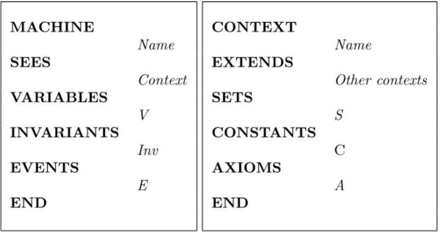
2.3.2.1 Machines and Contexts
An Event-B specification is made of two elements: context and machine. The machine is a fundamental component for the formal construction of a system in Event-B; it specifies its dynamic part. It includes elements such as variables V , invariants Inv, and events E that establish the system state change. The variables define the state of the system to be specified. The possible values that the variables hold are restricted using invariants written using first-order predicates. Invariants should remain valid in each state of the system. Thus, they should be valid in the initial state and after the execution of each event.
Machines often need static elements of the system such as constants C, sets S, and axioms A that specify their properties. These elements are included in a context that describes the static part of an Event-B specification. To have access to its elements,
2
Languages for Formal Process Representation 37
a context is seen by a machine (i.e. SEES Context). The structure of machines and contexts is depicted by Figure 2.6.
MACHINE Name SEES Context VARIABLES V INVARIANTS Inv EVENTS E END CONTEXT Name EXTENDS Other contexts SETS S CONSTANTS C AXIOMS A END
Figure 2.6: Event-B machine and context
An event can be executed if it is enabled, i.e. all the conditions G, named guards, prior to its execution hold. Among all enabled events, only one is executed. In this case, substitutions Act, called actions, are applied over variables. In this thesis, we restrict ourselves to the becomes equal substitution, denoted by (x := e). Each event has the form depicted in Figure 2.7.
Name ANY X WHEN G THEN Act END Name ANY Xr WHEN Gr THEN Actr END
Figure 2.7: Event-B event and refinement event
2.3.2.2 Refinement in Event-B
Refinement is a process of enriching or modifying a model in order to augment the functionality being modeled, or/and explain how some purposes are achieved. Both Event-B elements context and machine can be refined. A context can be extended by
38 Preliminaries
defining new sets Sr and/or constants Cr together with new axioms Ar. A machine
is refined by adding new variables and/or replacing existing variables by new ones Vr
that are typed with an additional invariant Invr. New events can also be introduced
to implicitly refine a skip event (i.e. It does not modify the already existing variables). In this thesis, the refined events have the same form (see Figure 2.7).
The main advantages of the refinement process are as follows:
– Simplification of proof obligations (POs) that allow to check the model correct-ness
– The complexity of the development is apportioned between the abstraction levels A stepwise refinement approach produces a correct specification by construction since we prove the different properties of the system at each step.
2.3.2.3 Verification and Validation of Event-B Models
This section describes two complementary techniques to ensure, respectively, the ver-ification and the validation of an Event-B specver-ification. In the verver-ification step, we formally check the properties of the system, which are expressed in terms of invariants, using formal proofs (proof obligations). POs allows to prove that invariants (both the abstract and the concrete ones) hold in all system states: they hold initially; and each event preserves them. And then, we adopt the validation of our formal model by animating our specification using the plug-in ProB. This step allows to discover and observe the behavior of our specification.
Proof Obligations In order to demonstrate the model correctness, a collection of proof obligations (POs) is generated by the Rodin tool [60]. These POs ensure that invariants are preserved by each event. Therefore, for each event, we have to establish that:
∀S, C, V, X. (A ∧ G ∧ Inv ⇒ [Act]Inv)
where [Act]Inv gives the weakest precondition on the before state such that the exe-cution of Act leads to an after state satisfying Inv.
To prove that a refinement is correct, we have to establish the following two proof obligations:
• guard refinement: the guard of the refined event should be stronger than the guard of the abstract one:
∀(S, C, Sr, Cr, V, Vr, X, Xr). (A ∧ Ar∧ Inv ∧ Invr ⇒ (Gr⇒ G))
• Simulation: the effect of the refined action should be stronger than the effect of the abstract one:
Languages for Formal Process Representation 39
∀(S, C, Sr, Cr, V, Vr, X, Xr). (A ∧ Ar∧ Inv ∧ Invr∧ [Actr]Invr ⇒ [Act]Inv)
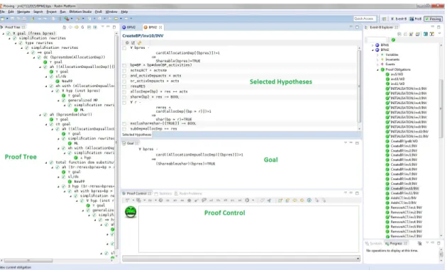
Formal definitions of all proof obligations are given in [50]. To discharge the different proof obligations, the Rodin3 platform offers an automatic prover but also the possibility to plug additional external provers like the SMT and Atelier B provers that we use in this work. Both provers offer an automatic and an interactive options to discharge the proof obligations. Complex proof obligations could be discharged interactively using the proving perspective of Rodin shown in Figure 2.8.
Figure 2.8: Prooving in Rodin
ProB (model checker/ animator) ProB [62] is an animator and explicit auto-matic model checker, originally developed for the verification and validation of soft-ware development based on the B language. Developed at the University of D¨usseldorf starting from 2003, ProB 4 implements an automatic model checking technique to check LTL (linear temporal logic) [49] and CTL (Computational Tree Logic) [63] properties against a B specification. The core of ProB is written in a logical pro-gramming language called Prolog. Its purpose is to be a comprehensive tool in the area of formal verification methods. Its main functionalities can be summarized up as follows:
3
http://www.event-b.org/install.html
4

![Figure 1.3: Configuration and Resources in the Business Process Lifecycle (adapted from [2, 3]).](https://thumb-eu.123doks.com/thumbv2/123doknet/11408938.288185/22.918.206.747.583.888/figure-configuration-resources-business-process-lifecycle-adapted.webp)

![Figure 3.1: An example of configuring a C-YAWL connector: from an OR-split to an XOR-split [4]](https://thumb-eu.123doks.com/thumbv2/123doknet/11408938.288185/48.918.226.749.137.319/figure-example-configuring-yawl-connector-split-xor-split.webp)
![Figure 3.3: An example of a C-EPC process model [1]](https://thumb-eu.123doks.com/thumbv2/123doknet/11408938.288185/49.918.277.614.168.669/figure-example-c-epc-process-model.webp)
![Figure 3.4: The provop approach of variant modeling [6]](https://thumb-eu.123doks.com/thumbv2/123doknet/11408938.288185/50.918.182.772.374.575/figure-provop-approach-variant-modeling.webp)
![Figure 3.5: An example of a questionnaire model [7]](https://thumb-eu.123doks.com/thumbv2/123doknet/11408938.288185/51.918.226.662.517.795/figure-an-example-of-questionnaire-model.webp)
![Figure 3.6: An example of a configured feature model generated after configuration step [8]](https://thumb-eu.123doks.com/thumbv2/123doknet/11408938.288185/52.918.235.713.369.679/figure-example-configured-feature-model-generated-configuration-step.webp)
