HAL Id: hal-00777924
https://hal.archives-ouvertes.fr/hal-00777924
Submitted on 2 Oct 2013
HAL is a multi-disciplinary open access
archive for the deposit and dissemination of sci-entific research documents, whether they are pub-lished or not. The documents may come from teaching and research institutions in France or abroad, or from public or private research centers.
L’archive ouverte pluridisciplinaire HAL, est destinée au dépôt et à la diffusion de documents scientifiques de niveau recherche, publiés ou non, émanant des établissements d’enseignement et de recherche français ou étrangers, des laboratoires publics ou privés.
Optimum Configuration for Discrete Multi-tone
Transmission over Polymer Optical Fiber
Linning Peng, Sylvain Haese, Maryline Hélard
To cite this version:
Linning Peng, Sylvain Haese, Maryline Hélard. Optimum Configuration for Discrete Multi-tone Trans-mission over Polymer Optical Fiber. 19th International Conference on Telecommunications, Apr 2012, Jounieh, Lebanon. �hal-00777924�
Optimum Configuration for Discrete Multi-tone
Transmission over Polymer Optical Fiber
Linning Peng, Sylvain Haese, Maryline Hélard
Institut d'Electronique et des Télécommunications de Rennes (IETR), UMR 6164 INSA, Université Européenne de Bretagne, 35708 Rennes, France
Linning.Peng@insa-rennes.fr
Abstract—High bit rate transmission over polymer optical fiber (POF) attracts great interests recently. This paper investigates the discrete multi-tone (DMT) transmission over 50-meter step-index POF (SI-POF) based on an experimental system. The system adopts a digital storage oscilloscope (DSO) and processes the data off-line, which is the most common solution in the POF researches. We first study the problem of effective number of bits (ENOB) in the DSO’s analog-to-digital converter (ADC). Then we investigate the optimum configuration of the DMT transmission in terms of subcarrier number selection, clipping and ADC quantization effect mitigation. The proposed method of selecting optimum configuration can be easily applied to any other DMT over POF systems.
I. INTRODUCTION
Polymer optical fibers (POFs) are proposed to work as one of high-speed short range communication media. As one research issue in the seventh framework program (FP7) “Architectures for Flexible Photonic Home and Access networks” [1], POF attracts more and more researchers to exploit its potential to support ultra high-speed transmission in short range [2].
Derived from the generally well-known orthogonal frequency division multiplexing (OFDM) [3], discrete multi-tone modulation (DMT) is a baseband version of multicarrier modulation technique. A significant advantage of DMT is the possibility to allocate various arbitrary numbers of bits per subcarrier, according to the corresponding signal-to-noise (SNR) of each subcarrier [3]. With the low-cost consideration, intensity modulation with direct detection (IM/DD) structure is universally adopted in POF transmission, in particular employing baseband modulated DMT. However, DMT requires high sampling rate and high bit resolution of digital-to-analog converters (DAC), digital-to-analog-to-digital converters (ADC). In most POFs experiments adopting off-line processing, an arbitrary waveform generator (AWG) and a digital storage oscilloscope (DSO) were used to meet the requirement of high sampling rate and bit resolution of DAC/ADC [2][4]. However, the quantization noise caused from effective number of bits (ENOB) in ADC of DSO is a significant impairment to overall performance in optical communications [5]. Meanwhile, the inherent large peak-to-average power ratio (PAPR) in DMT modulation enhances the DAC/ADC bit resolutions requirement, which needs PAPR reduction techniques, such as clipping [6]. In recent researches, POF transmission with different clipping levels and number of subcarrier selection is
analyzed [4], yet without cyclic prefix (CP) length influence consideration.
In this paper, several issues about the optimum configuration for DMT transmissions over POF are mentioned. Section II describes the DMT transmission over optical IM/DD channel. Section III outlines POF experimental setup. In Section IV, the ENOB influence in POF transmission is first introduced. Then ENOB enhancement techniques and its benefit in POF transmission are also analyzed. Section V presents an overall optimization of DMT transmission over POF, including quantization noise reduction, subcarrier number selection and optimal clipping. Section VI concludes the paper.
II. DMT TRANSMISSION OVER OPTICAL IM/DD CHANNEL
A. DMT Transmitter
DMT transmission is employed in asymmetric digital subscriber line (ADSL) technology. Contrary to OFDM, DMT modulation generates only real-value signals after inverse fast Fourier transform (IFFT). Thus DMT do not require additional analog radio frequency (RF) components to mix I/Q channels. However, in order to achieve real-valued signals, twice length of IFFT is needed for DMT modulator [7].
DMT modulation can be illustrated as follows:
(1)
(2)
where is a modulated real-valued DMT signal, which require 2N points of IFFT in (1). The original signal follows Hermitian symmetry property in (2).
B. Bit-loading in DMT
A significant advantage of DMT is the possibility to allocate the number of bits transmitted in each subcarrier according to its SNR value, which can maximize channel capacity with the implementation of corresponding quadrature amplitude modulation (QAM) constellation size.
Rate-adaptive bit-loading algorithm is widely used. The maximal bit-rate in DMT transmission considering the SNR restraint and system margin is given by [8]:
where, is total available subcarrier number in DMT, is the SNR of subcarrier, is the gap between the SNR required to achieve Shannon capacity and the SNR to achieve this capacity at a given bit error rate, is optimal system performance margin.
C. Optical IM/DD Channel
In low-cost optical IM/DD channel, only light intensity is modulated. At the transmitter side, DAC output electrical signal directly drives the electro-optical component (resonant-cavity light-emitting diodes RC-LED or vertical-(resonant-cavity surface emitting laser VCSEL). A DC-bias is commonly added to DMT bipolar electrical signal, in order to drive the electro-optical component. After that, the electrical signal is linearly converted to optical power. At the receiver side, light is captured by photodetector (PD) and optical power intensity is directly converted to electrical current. A transimpedance amplifier (TIA) is usually added after PD to amplify signals to appropriate ADC range. Finally, signal is sampled and quantized by ADC.
All the degradations in IM/DD channel generally come from following issues:
Non-linearity distortion is generated from the non-linearity function of electro-optical component. Increasing signal current benefits higher emitted signal power, whereas suffers the non-linearity phenomenon. Thermal noise is mostly generated from PD and TIA,
which can be modeled as additive white Gaussian noise (AWGN).
Clipping noise is common in DMT modulation. Due to the finite dynamic range of DAC/ADC, clipping is usually performed digitally before DAC.
Quantization noise is generated from the effect of quantization in DAC/ADC, due to the finite bit resolution of components.
Normalized SNR in IM/DD channel is represented as [9]:
where is signal power, is the interference caused from non-linearity distortion, is thermal noise,
is clipping noise and is quantization noise.
Normalized SNR can be optimized with deliberate DMT system configuration.
D. POF Channel
There exist various types of POF. Polymethyl-methacrylate (PMMA) step-index POF (SI-POF) is the most common one. Compared to silica optical fiber, SI-POF owns 1-mm large core-diameter, which benefits easier connection installation and
larger tolerances to bending. In addition, visible light transmission over SI-POF benefits the safety of eyes.
However, due to 1-mm core-diameter and high numerical aperture (NA) of standard SI-POF, millions of modes exist in SI-POF, which causes significant modal dispersion (MD) [10]. Resulting from the high MD, transmission bandwidth in SI-POF is limited around 50 MHz×100m. The low-pass channel frequency response of POF channel can be modeled as Gaussian filter [8] [10], which is represented by:
, with (5)
where is the -3dB POF channel bandwidth.
Meanwhile, POF suffers high attenuation in transmission. Attenuation in SI-POF at 650 nm wavelength is around 150 dB/km [10], which limits the SI-POF application only in short-range transmission.
The chromatic dispersion (CD) in PMMA-POF is over 300 ps/nm·km at 650 nm wavelength [10]. However, due to the short-range transmission, the real influence of CD in DMT transmission is negligible.
III. EXPERIMENTAL SETUP
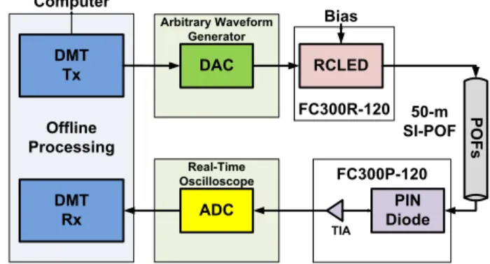
An experimental setup diagram is described in Fig. 1. Commercially available components such as RC-LED and PIN diode with TIA are used according to the low-cost consideration. DMT symbols are pre-generated in computer and stored in the AWG memory. The AWG output directly drives RC-LED (FC300R-120) with a proper bias. After transmission over 50 m SI-POF, signal is received by PIN diode (FC300P-120) and subsequently captured by DSO. Finally, off-line digital signal processing is implemented in Matlab/Simulink. FC300R-120 FC300P-120 Offline Processing DMT Tx DMT Rx Computer Arbitrary Waveform Generator Real-Time Oscilloscope DAC ADC RCLED PIN Diode P O F s Bias 50-m SI-POF TIA
Figure 1. Experimental setup of optical IM/DD channel
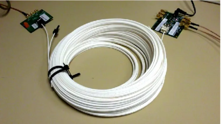
Fig.2 manifests experimental transceivers, which are all commercially available. Fig.3 shows the photography of our experimental setup.
Channel frequency response of system transmission chain with 50-m SI-POF that we measured is given in Fig.4. Due to the high dispersion of large core-diameter SI-POF with high numerical aperture, the measured system 3-dB bandwidth with 50-m SI-POF (Eska™ Premier) is limited to 80 MHz.
The frequency response attenuation is significant for high frequencies. However, system capacity also depends on the overall SNR in (4). Optimum configuration such as reducing quantization noise by mean of increasing ADC bit resolution; enlarging signal power by mean of moderate
Figure 2. Commercially available electro-optical components and 50-m SI-POF
Figure 3. Experimental setup
Figure 4. Channel frequency response of 50-m SI-POF system
clipping, can enhance the SNR in (4), which maximizes system performance.
From subcarrier SNR measurement results presented in Section IV, the useable bandwidth is around 0-250 MHz with the utilization of DMT modulation and bit-loading technique.
When we compare DMT modulation with different subcarriers selection, CP length consideration is also important. From channel impulse response presented in Fig.5, the CP length of each DMT symbol can be fixed to 8 ns, in order to obtain the trade-off between minimal inter-symbol interference (ISI) and maximum spectral efficiency of DMT modulation.
Figure 5. System impulse response after 50-m SI-POF
IV. ADC’S ENOB IN IM/DD CHANNEL
High-speed ADCs are largely used in communication, digital oscilloscope and radar. Flash and time-interleaved architectures are typically used for high-speed ADCs. However, power consumption in flash ADC increases drastically with the ADC bit-resolution increment, thus limiting practical ADC bit-resolution to less than 6 bits [11]. ADCs in high performance DSO are usual with high-speed (Multi-Giga samples/sec) and low-middle bit resolution (4-8 bit). Moreover, in most of real ADCs, ENOB is smaller than nominated resolution [11], which enhances the influence of quantization noise in ADC.
A. ADC ENOB measurement
In our experiments, at the transmitter side, AWG with DAC working with 10 bit resolution and maximum sampling rate of 5 GS/s is used to generate DMT waveforms. At the receiver side, DSO with ADC working at 8 bit resolution and maximum sampling rate of 40 GS/s is employed to capture the DMT waveforms. The AWG bit resolution is 2 bits better than that of DSO, therefore quantization noise mainly comes from the DSO’s ADC.
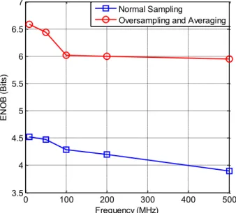
ENOB can be measured by spectrum analysis of pure sinusoid signal converted in ADC [12]. Our measured 8 bits ADC ENOB frequency response is depicted in Fig.6, which shows approximately from 4 to 4.5 bits ENOB in the 0-500 MHz frequency range. It is noticeable that ADC quantization noise in DSO is significant in IM/DD channel experiment, especially in DMT transmission over POF with high order modulation (64-QAM or even more).
B. ENOB enhancement with oversampling and averaging
The quantization signal-to-noise ( ) in DMT transmission system can be given as [13]:
0 100 200 300 400 500 -80 -70 -60 -50 -40 -30 -20 Frequency (MHz) R e sp o n se ( d B ) 50-m SI-POF (RCLED Bias: 18.3mA)
0 5 10 15 20 25 -5 0 5 10 15 20 Time (ns) A m p lit u d e ( m V )
(6) where is ENOB, is the ratio between the root-mean-square and the peak voltage ratio of the DMT signal, and is the oversampling factor.
From (6), it is clear that increasing sampling rate improve . One efficient approach of bit resolution enhancement is oversampling and averaging [14].
The theoretical relationship between oversampling value and ENOB enhancement is given as [14]:
(7)
where is original sampling rate, is oversampling value and is additional bits after oversampling.
The measured ENOBs enhancement of the ADC in our DSO with 32x oversampling is also depicted in Fig. 6. The ENOB enhancement is near 2 bits after oversampling and averaging, which is slightly less than theoretical calculation of 2.5 bits.
Figure 6. Measured ADC ENOBs in DSO
One comparison of the oversampling improvement in our POF transmission experiment is illustrated in Fig. 7. DMT signal with 32 subcarriers over a 312 MHz frequency band is transmitted across 50 m SI-POF with ADC working at two different sampling rates: Nyquist sampling rate and 32x oversampling rate. The performance with ADC working at a 32x oversampling rate owns a 2-3 dB gain compared to performance of ADC only working at Nyquist sampling rate. It is obvious that is enhanced, nevertheless the system complexity is significantly increased. In theoretical calculation of (6) (7), enhancement should be around 15 dB after 32x oversampling. However, due to system non-linearity distortion and noise in formula (4), the enhanced SNR of
DMT transmission over POF is limited to less than 30 dB with low-cost commercial components.
Figure 7. SNR in DMT subcarriers with ADC works at two sampling rates
V. JOINT SUBCARRIER NUMBER SELECTION AND CLIPPING OPTIMIZATION IN DMT TRANSMISSION
The total bit rate of DMT transmission depends on subcarrier number selection in case of fixed CP length. System with larger subcarrier number owns higher DMT spectral efficiency, which performs higher bit rate. However, in multi-carrier modulation system such as OFDM and DMT, modulated subcarriers may incidentally add together, which cause unexpected peaks in modulated symbols [15]. As we know, PAPR increases when subcarrier number increases [15], which degrades in (1). Clipping technique is verified as a straightforward approach to reduce PAPR [15], but unfortunately clipping generates noise in each DMT subcarrier. The clipping process can be illustrated as follows:
(8) where is original symbol, is clipping threshold defined by clipping ratio :
(9) From (6), could be enhanced with low value of clipping ratio . However, is increased in (4), which degrades system SNR. After oversampling and averaging in ADC, system SNR in (4) can be optimized with the joint subcarrier number selection and clipping optimization.
250 MHz bandwidth DMT probing symbols with QPSK modulation are generated in the AWG with 1 GS/s sampling rate. With system complexity consideration, the received data are captured in DSO with 2.5 GS/s sampling rate (5x
0 100 200 300 400 500 3.5 4 4.5 5 5.5 6 6.5 7 Frequency (MHz) E N O B ( B its) Normal Sampling
Oversampling and Averaging
0 78 156 234 312 5 10 15 20 25 30 35 40 Frequency (MHz) S N R ( d B )
ADC with Nyquist Sampling Rate
oversampling). After off-line processing of synchronization and ENOB enhancement in Fig.8, available channel capacities are measured with different configurations including subcarrier selection and clipping. Rate-adaptive bit loading algorithm with 10-4 BER limitation is adopted to maximize the
channel capacity.
Offline Processing in Matlab & Simulink
Equalization AWG DSO DAC (10 Bits) ADC (8 Bits) PSK Probing Symbols Estimate SNR Down-Sampling if Necessary Up-Sampling if Necessary Clipping IFFT & Adding CP Remove CP & FFT
Figure 8. Off-line processing of subcarrier SNR estimation
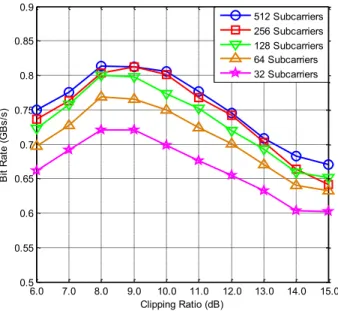
The joint subcarrier number selection and clipping ratio investigation of the total bit rate of DMT transmission has been done in Fig. 9:
Figure 9. DMT optimum configuration with joint subcarrier number selection and clipping optimization
The maximal bit rate performances are achieved around 9 dB clipping and DMT modulation with 512 subcarriers. In addition, the performance differences between 512 and 256 subcarrier numbers are negligible around optimal clipping. It can be inferred that higher than 512 subcarrier number selection is unnecessary, especially with system complexity consideration. However, on the other hand, due to CP length penalty, the overall performances are degraded when subcarrier number decreases, especially in cases of 32 and 64 subcarriers.
VI. CONCLUSION
In this paper, DMT transmissions over 50-m SI-POF with various configurations are carefully investigated, in order to get the optimum DMT configuration in POF transmission. A typical IM/DD DMT transmission system over POF with simplified setup is described. It is shown that measured ENOB in DSO’s ADC is smaller than nominated bits resolution. The influence of limited ENOB to DMT transmission is explained. With oversampling technique, higher ENOB can be obtained in ADC, which maximizes DMT transmission performances. Meanwhile, system performances can be improved by increasing the subcarrier number. The larger the number of subcarriers, the higher the performance. Nevertheless, 256 subcarriers is a good tradeoff between performances and complexity. Finally, the optimal clipping ratio is investigated with different subcarrier numbers. Measured results manifest that around 9 dB clipping is the rational value to optimize system throughput.
REFERENCES
[1] www.ict-alpha.eu (ICT ALPHA project web-site)
[2] C.M.O konkwo, E. Tangdiongga, H. Yang, et. al. “Recent Results from the EU POF-PLUS Project: Multi-Gigabit Transmission over 1 mm Core Diameter Plastic Optical Fibers”, Journal of Lightwave Technology, vol. 29, no. 2, pp. 186-193, Jan.15 2011
[3] S. Randel, F. Breyer, J. Lee, J. Walewski, “Advanced Modulation Schemes for Short-Range Optical Communications”, IEEE Sel. Topics in Quantum Electronics, vol. 16, no. 5, pp. 1280-1289, Sep-Oct 2010 [4] S.C.J. Lee, F. Breyer, S. Randel, O. Ziemann, H.P.A. van den Boom,
A.M.J. Koonen, “Low-Cost and Robust 1-Gbits Plastic Optical Fiber Link Based on Light-Emitting Diode Technology”, OFC/NFOEC, 2008 [5] B. Mao, N. Stojanovic, C. Xie, M. Chen, L.N. Binh, N. Yang, “Impacts
of ENOB on the Performance of 112Gbps PDMQPSK Digital Coherent Receiver”, ECOC, 2011
[6] C.R. Berger, Y. Benlachtar, R.I. Killey, and P.A. Milder, “Theoretical and experimental evaluation of clipping and quantization noise for optical OFDM”, Optics Express, vol. 19, issue 18, pp. 17713-17728, Aug.25 2011
[7] Asymmetric Digital Subscriber Line (ADSL) Transceivers, ITU Std. G.992.1, July 1999.
[8] P.S. Chow, J.M. Cioffi, and J.A.C. Bingham, “A Practical Discrete Multitone Transceiver Loading Algorithm for Data Transmission over Spectrally Shaped Channels”, IEEE Transactions on Communications, vol. 43, no. 234, pp. 773-775, Feb/Mar/Apr 1995
[9] J. Lee, “Discrete Multitone Modulation for Short-Range Optical Communications”, Ph.D dissertation, TU/e, 2009
[10] O. Ziemann, J. Krauser, P.E. Zamzow, W. Daum, “POF Handbook: Optical Short Range Transmission Systems”, 2nd Edition, Springer, 2008
[11] E.H. Chen, C.K.K. Yang, “ADC-Based Serial I/O Receivers”, IEEE Transactions on Circuits and Systems, vol. 57, no. 9, pp. 2248-2258, Sep 2010
[12] www.spec.de, “Measuring of dynamic figures: SNR, THD, SFDR” (SPECTRUM web-site)
[13] B. Inan, S.C.J. Lee, S. Randel, I. Neokosmidis, A.M.J. Koonen, and J.W. Walewski, “Impact of LED Nonlinearity on Discrete Multitone Modulation”, Journal of Optical Communications and Networking, vol. 1, issue 5, pp. 439-451, Oct 2009
[14] www.cygnal.com, “Improving ADC Resolution by Oversampling and Averaging”, (Cygnal Integrated Products web-site)
[15] W.Shieh, I.Djordjevic, “OFDM for Optical Communications”, Academic Press, Oct 2009
6.0 7.0 8.0 9.0 10.0 11.0 12.0 13.0 14.0 15.0 0.5 0.55 0.6 0.65 0.7 0.75 0.8 0.85 0.9 Clipping Ratio (dB) B it R at e (G B s/ s) 512 Subcarriers 256 Subcarriers 128 Subcarriers 64 Subcarriers 32 Subcarriers