Study of Temperature in the Edge Milling of Carbon
Fiber-Reinforced Plastic (CFRP)/Ti6Al4V Stack Material for
Aerospace Industry
by
Arquimedes CASTILLO
THESIS PRESENTED TO ÉCOLE DE TECHNOLOGIE SUPÉRIEURE IN
PARTIAL FULFILLMENT OF A MASTER’S DEGREE WITH THESIS IN
AEROSPACE ENGINEERING
M. A. Sc.
MONTREAL, NOVEMBER 27, 2019
ÉCOLE DE TECHNOLOGIE SUPÉRIEURE UNIVERSITÉ DU QUÉBEC
This Creative Commons license allows readers to download this work and share it with others as long as the author is credited. The content of this work can’t be modified in any way or used commercially.
BOARD OF EXAMINERS
THIS THESIS HAS BEEN EVALUATED BY THE FOLLOWING BOARD OF EXAMINERS
Prof. Jean-François Chatelain, Thesis Supervisor
Department of Mechanical Engineering, École de Technologie Supérieure
Prof. Gilbert Lebrun, Thesis Co-supervisor
Department of Mechanical Engineering, Université du Québec à Trois-Rivières
Prof. Sébastien Lalonde , President of the Board of Examiners
Department of Mechanical Engineering at École de technologie supérieure
Prof. Vincent Demers, Member of the jury
Department of Mechanical Engineering at École de technologie supérieure
THIS THESIS WAS PRENSENTED AND DEFENDED
IN THE PRESENCE OF A BOARD OF EXAMINERS AND PUBLIC NOVEMBER 20, 2019
ACKNOWLEDGMENT
To start, I would like to thank for all the help and support that I received over the time during my research and writing of my master thesis. Without the assistance of so many people in different ways, it could not have been possible.
I am grateful to my supervisor; Professor Jean-François Chatelain for his guidance, supervision, support and encouragement to complete this thesis. In addition, I would like to express my special thanks to my co-supervisor Prof. Gilbert Lebrun and to Dr. Xavier Rimpault, post-doctoral fellow at École Technologie Supérieur. I would also like to express my gratitude to Daniel Legault, Eric Marcoux, Joel Grignon, Louis-David Archambault, Nabil Mazeghrane for their technical training as well as, Mr. Mario Bilodeau, from MISTRAS group, for taking X-rays films. Moreover, I would like to thank all my laboratory partners who made me spend pleasant moments in the Composite Materials Lab.
In addition, I want to thank CONACYT for the financial support and the opportunity to study abroad and most importantly; I must express my very profound gratitude to my parents and, my brothers for providing me with unfailing support and continuous encouragement throughout my life and through the process of researching and writing of this thesis. In spite of the geographical distance, you were always nearby with me. Definitely, this accomplishment would not have been possible without you. This thesis is dedicated to you!
Finally, I would like to be grateful for all the people who are mentioned or not with whom I shared sweet moments during my sejour.
Étude de la température lors de l'usinage des bords de matériaux en CFRP/Ti6Al4V pour l'industrie aérospatiale
Arquimedes CASTILLO MORALES
RÉSUMÉ
Avec les progrès des nouvelles technologies et des nouveaux matériaux, les industries aérospatiales, militaires et commerciales cherchent à réduire la consommation de carburant en réduisant le poids de leurs structures et composantes. Les matériaux stratifiés hybrides sont plus souvent utilisés dans les cellules aéronautiques en raison de leurs propriétés mécaniques exceptionnelles telles qu'un rapport résistance/poids élevé, une excellente résistance à la corrosion et à la fatigue qui ne peuvent être obtenues avec des matériaux classiques.
Le plastique renforcé de fibres de carbone (CFRP)/Titane est le type de matériau hybride le plus utilisé pour les applications de charge thermique dans l'aviation, le Ti6Al4V étant le plus populaire des alliages de titane. Habituellement, les plaques de CFRP/Ti6Al4V sont assemblées par des rivets ou des boulons; mais dans le cas de quelques applications les deux matériaux sont collés ou directement fusionnés par le biais de la polymérisation de la résine. Ainsi, le processus de perçage n'est pas nécessaire comme il l’est habituellement, ce qui permet de réduire les coûts et le poids de la cellule aéronautique. La différence d'usinabilité et l'invariabilité en température de chaque matériau font de l'obtention de géométries et de tolérances dimensionnelles spécifiques un véritable défi. Cette thèse étudie les effets thermiques sur un stratifié CFRP/Ti6Al4V dans le processus de détourage. En particulier, nous étudions la méthode thermocouple outil-pièce en utilisant des thermocouples commerciaux. De plus, nous étudions les réponses “forces”, “rugosité”, et “l'usure des outils” pour différents types de fraises en variant la vitesse de coupe, l'avance par dent et la profondeur radiale de la coupe.
Nous avons constaté que contrairement à ce que l'on pensait auparavant, le facteur d'avance est le plus influent sur la température de coupe du CFRP/Ti plutôt que la vitesse de coupe. En
fait, la température dans la pièce augmente en diminuant l'avance par dent et diminue en augmentant la vitesse de coupe, bien que ce dernier facteur ne soit pas aussi important que l'avance par dent.
Mots-clés: CFRP/Ti6Al4V stack, étude thermique, fraisage des arêtes, thermocouple
Study of temperature in edge milling process of carbon fiber-reinforced plastic (CFRP)/Ti6Al4V stack material for aerospace industry
Arquimedes CASTILLO MORALES
ABSTRACT
With the advances of new technologies and new materials, aerospace, military and commercial aircraft industries are looking to decrease the fuel consumption by reducing weight into their structures and components. Hybrid or stacks of materials are used more often in airframes because of their outstanding mechanical properties such as high strength/weight ratio and, excellent corrosion and fatigue resistance that cannot be provided with metallic materials.
Carbon Fiber-Reinforced Plastic (CFRP)/Titanium is the most used type of hybrid material for thermal-load applications in aviation, Ti6Al4V being the most popular of the titanium alloys. Usually, CFRP/Ti6Al4V plaque is assembled by rivets or bolts; however, there are some applications where both materials are bonded or cured together. Thus, the drilling process is not required as it usually happens, removing cost and weight from the airframe. The difference in machinability and the temperature invariability of each material makes achieving specified geometries and dimensional tolerances a real challenge. Therefore, this thesis studies the thermal effects on CFRP/Ti6Al4V in the process of edge milling. In particular, we study the tool-workpiece thermocouple method by using commercial thermocouples. Additionally, we study the effects of cutters while varying cutting speed, feed per tooth and radial depth of cut on the forces, roughness and tool wear for the different types of cutters.
We found that, as opposed to what was previously thought, the feed factor is the most influent one regarding the cutting temperature for the CFRP and Ti workpiece instead of the cutting speed. It has been found that the temperature in the workpiece increases by decreasing feed per tooth and decreases by increasing the cutting speed, although this last factor is not as significant as the feed per tooth.
Keywords: CFRP/Ti6Al4V stack, cutting temperature, edge milling, embedded thermocouple, tool-workpiece method
TABLE OF CONTENTS
Page
INTRODUCTION ...1
Research problematic ...3
CHAPTER 1 LITERATURE REVIEW ...5
1.1 Stack of materials ...5
1.1.1 Introduction to composite materials... 5
1.1.2 Carbon Fiber Reinforced Plastic (CFRP) ... 7
1.1.3 Ti6Al4V alloy ... 8
1.1.4 CFRP/Ti6Al4V plaque ... 8
1.2 Machining process operations ...11
1.2.1 Milling parameters ... 12
1.2.2 Cutting tools ... 13
1.2.3 Cutting forces ... 14
1.2.4 Chip formation in the cutting process of CFRP ... 17
1.2.5 Surface roughness ... 19
1.3 Thermal effects during machining ...21
1.3.1 Temperature measurement methods ... 22
1.3.2 Influence of cutting temperature in the machining process ... 26
1.3.3 Thermal aspects during machining CFRP ... 28
1.3.4 Heat flux in CFRP plaque ... 33
1.4 Summary of the literature review ...34
1.4.1 Objective ... 34
CHAPTER 2 METHODOLOGY ...37
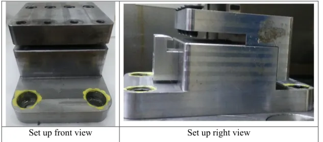
2.1 Machine and Setup ...37
2.2 Selection of cutting tool ...38
2.3 Screening of experiment ...41
2.4 Design of Experiments ...42
2.5 Manufacturing of CFRP/Ti6Al4V plaques ...46
2.5.1 Manufacturing process of CFRP plaques ... 47
2.5.2 Embedded thermocouples in CFRP ... 49
2.5.3 Thermocouples on the cutting tool ... 56
2.6 Edge milling of [0]8/Ti6Al4V plaques ...57
2.6.1 Workpiece and cutter temperature measurement ... 58
2.6.2 Cutting Forces ... 60
2.6.3 Roughness on CFRP/Ti6Al4V ... 61
CHAPTER 3 RESULTS AND DISCUSSION ...65
3.1 Temperature on the workpiece and cutter ...65
3.1.1 Analysis of temperature on the Ti workpiece ... 65
3.1.2 Analysis of temperature in the CFRP workpiece ... 71
3.1.3 Analysis of temperature on the cutters ... 80
3.2 Analysis of Forces...84 3.2.1 Feed force ... 84 3.2.2 Normal force ... 87 3.2.3 Axial force ... 89 3.3 Roughness Analysis ...92 3.4 Tool wear ...97 CONCLUSION ...103 RECOMENDATIONS ...105 BIBLIOGRAPHY ...119
LIST OF TABLES
Page
Table 1-1 Advantages vs Disadvantages of CFRP/Ti6Al4V ...9
Table 2-1 Machine Huron specification ...37
Table 2-2 Niagara tool or Tool number 1 specifications ...39
Table 2-3 Walter tool or Tool number 2 specifications ...40
Table 2-4 Onsrud tool or Tool number 3 specifications ...40
Table 2-5 Thermal conductivity of the different cutters ...41
Table 2-6 Final DOE ...42
Table 2-7 Physical properties of Ti6Al4V ...48
Table 2-8 Prepeg CYCOM® 5320-1 T650-35 3K 8HS Fabric 36% physical properties ...50
Table 2-9 Thermocouple workpiece statistical analysis ...55
Table 2-10 Real DOE...58
Table 2-11 Mitutoyo Surftest SJ400 input parameters ...63
Table 3-1 Cutter tool wear progress at different cutting parameters for the ae of 1 mm ...100
Table 3-2 Cutter tools wear progress at different cutting parameters for the ae of 4.3 mm ...101
LIST OF FIGURES
Page
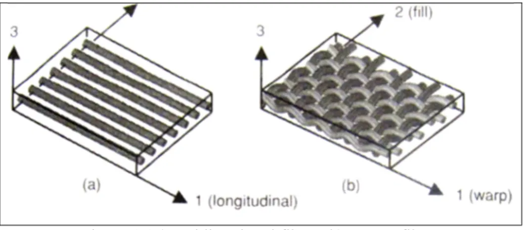
Figure 1.1 a) Unidirectional fibers, b) woven fibers ...7
Figure 1.2 Airframe material composition on Boeing 787 Dreamliner ...10
Figure 1.3 Material composition in airplanes Airbus ...10
Figure 1.4 Edge milling operation ...11
Figure 1.5 Up milling/Down milling ...12
Figure 1.6 Cutters used for CFRP ...14
Figure 1.7 Diagram of orthogonal cutting forces ...15
Figure 1.8 Different stages in the orthogonal cutting process of CFRP/Ti at Ɵ of 0° , v of 50m/min and f of 0.20 mm/rev ...17
Figure 1.9 Cutting mechanisms in orthogonal machining of CFRP ...19
Figure 1.10 Schematic roughness representation ...20
Figure 1.11 Example of main problems in machining CFRP ...21
Figure 1.12 Thermography's examples ...23
Figure 1.13 Embedded thermocouple methods in CFRP and Ti materials ...25
Figure 1.14 An experimental investigation in milling Ti6Al4V...27
Figure 1.15 Analysis of thermal effects on the fiber orientation ...30
Figure 1.16 Thermal analysis in CFRP milling for different fiber orientation ...31
Figure 1.17 Example of thermal damage observed by SEM ...32
Figure 2.1 Setup for CFRP/Ti ...38
Figure 2.2 Sketch of final DOE with inputs and outputs ...43
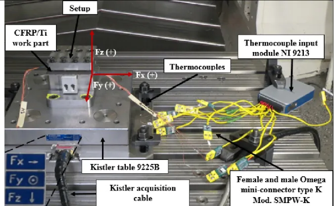
Figure 2.3 Schematic diagram of the acquisition equipment used in the experiments ...44
Figure 2.4 Forces and Temperature acquisition equipment
in the final experiment ...45
Figure 2.5 M320 Telemetry system ...45
Figure 2.6 Sketch of thermocouple order in CFRP/Ti stack ...46
Figure 2.7 Sketch of thermocouple position on Ti6Al4V plaque ...47
Figure 2.8 Thermocouple welding tip view ...48
Figure 2.9 Thermocouple micro-welding sample plaque ...49
Figure 2.10 Thermocouples setup process ...51
Figure 2.11 Flowchart of [0]8/Ti6Al4V fabrication process ...53
Figure 2.12 X-ray scanning example result ...54
Figure 2.13 Example of thermocouple outside the titanium plaque due to the curing process ...56
Figure 2.14 Embedded thermocouple process ...57
Figure 2.15 PCD tool , v 50 m/min, ft 0.15 mm/tooth, ae 1 mm example ...59
Figure 2.16 Methodology to know the correct position of thermocouples ...60
Figure 2.17 Forces layout setup ...61
Figure 2.18 Roughness setup ...62
Figure 2.19 Setup to measure tool wear ...64
Figure 3.1 Main effect plot for average temperature result on the Ti plaque T1 and T4 ...66
Figure 3.2 Pareto chart: Most significant factor on the titanium plaque and 3D graph on T4 ...66
Figure 3.3 Workpiece temperature on Ti plaque against thermocouple distance for a ft of 0.05 mm/tooth, v of 175 mm/tooth ...68
Figure 3.4 Longitudinal cutting profile for tool #2 (a, b) and tool #3 (c,d) at ft of 0.05 mm/tooth, v of 175 m/min and an ae of 1 mm ...69
Figure 3.5 Temperature through the longitudinal distance for the titanium plaque using tool #3, v of 175m/min,
ft of 0.05 mm/tooth and ae of 1mm ...70
Figure 3.6 Pareto Chart of the Standardized effects on T5 and T7 ...71
Figure 3.7 Pareto Chart of the Standardized effects on T6 and T8 ...72
Figure 3.8 Pareto Chart of the Standardized effects on T10 and T9 ...72
Figure 3.9 Workpiece temperature on Ti and CFRP VS thermocouple distance for ft of 0.05 mm/tooth, ae of 1 mm on (T2, T5, T7 and T9) and (T3, T6, T8 and T10) ...74
Figure 3.10 Vertical cutting temperature at a cutting length of 38.1 mm (thermocouples 2-5-7-9) ...75
Figure 3.11 Temperature through the thick distance T/C 2-5-7-9 for the [0]8/Ti6Al4V plaque using tool #3, v of 175m/min, ft of 0.05 mm/tooth and ae of 1mm ...77
Figure 3.12 Vertical cutting temperature at a cutting length of 63.3 mm (thermocouples 3-6-8-10) ...78
Figure 3.13 Temperature through the thick distance T/C 3-6-10 for the [0]8/Ti6Al4V plaque using tool #3, v of 175m/min, ft of 0.05 mm/tooth and ae of 1mm ...79
Figure 3.14 Main effect plot for cutter temperature and standardized pareto chart ...81
Figure 3.15 3D Graph cutter temperature (a) feed per tooth vs radial depth of cut for a v of 175m/min (b) Type of tool vs radial depth of cut for a ft of 0.05 mm/tooth ...82
Figure 3.16 Scheme of applied forces on the CFRP/Ti ...84
Figure 3.17 Main effect plot for average Feed force result and standardized pareto chart ...85
Figure 3.18 Feed force as a function of the feed per tooth according to the different cutting parameters on each cutter ...86
Figure 3.19 Normal force as a function of the feed per tooth according to the different cutting parameters on each cutter ...88
Figure 3.20 Main effect plot for axial force result and
standardized pareto chart ...89 Figure 3.21 Axial force as a function of the feed per tooth
according to the different cutting parameters on each cutter ...91 Figure 3.22 Main Effect plot of Ra in function to different parameters giving
by ±SEM and Ra Pareto chart of the most significant factor ...93 Figure 3.23 Ra on the CFRP plaque in function of different cutting
parameters v, ae and ft giving by ±SEM ...95 Figure 3.24 Ra on the Ti6Al4V plaque in function of different cutting
parameters v, ae and ft giving by ±SEM ...96 Figure 3.25 Main effect plot for tool wear and standardized pareto chart ...97 Figure 3.26 Tool wear effect on each cutting tool by using different
LIST OF ABBREVIATIONS
CFRP Carbon Fiber Reinforced Plastic Ti Titanium
Al Aluminum
G Glass fibers
C Carbon fibers
K Kevlar
PMC Polymer matrix composite
MMC Metal matrix composite
CMC Ceramic matrix composite
PCD PolyCristallline Diamond
SEM Scanning Electron Microscope, Standard Error of the mean CNC Computer Numerical Control
LIPPS Laboratoire d'ingénierie des produits, procédés et systèmes DOE Design of Experiments
ÉTS École de Technologie supérieure
CI Confidence Intervals
RSM Response-surface methodology
VB Flank wear
LIST OF SYMBOLS AND UNITS OF MEASUREMENTS
E1 Load in the fiber direction
E2 Load in the transversal direction
Tg Glass transition (°)
α Coefficient of thermal expansion
β Coefficient of moisture expansion
ae Radial depth of cut (mm)
V Cutting speed (m/min)
fr Feed rate (mm/min)
ft Feed per tooth (mm/rev-tooth) or (mm/z)
f Feed (mm/rev)
D Cutter Diameter (m)
N Spindles speed (rev/min)
hc Cut chip thickness (mm)
Fn Normal force to shear plane (N), Force in Y (N)
Fs Shear force (N)
Fu Friction force (N)
Fv Normal force to tool face
Fa Axial force, Force in Z(N)
Ft Tangential force (cutting force)
Ff Feed force, thrust force, force in X (N)
α Rake angle (°) β Friction angle φ Shear angle (°) Fr Radial force (N) R Result force (N) β Helix angle (°)
θ Fiber orientation (°), cutter diameter (mm)
Rv Arithmetic means to the valley height
Rz Arithmetic ten points average height
Rt Arithmetic maximum peak to the valley height
Rp Arithmetic maximum peak to mean height
υ Cutting energy, fiber volume (%)
k Thermal conductivity
p Density
c Specific heat
Km Matrix thermal conductivity W/mK)
Kf Fiber thermal conductivity (W/mK)
Vf Fiber volume fraction
ΔT Difference of temperature
qs Strength of the heat source
c Specific heat capacity
α Heat dissipation rate
y Shortest distance from the heat source
X Moving distance of the cutter
λc,θ Composite thermal conductivity
Λc,p Parallel thermal conductivity to fiber orientation
Λc,t Transversal thermal conductivity to the fiber direction
Q Mechanical power transformed to heat
Qt Heat conducted by the tool
Qw Heat conducted by the workpiece
Qc Heat conducted by the chip
Pel Electrical power consumed by the machine
η Spindle efficiency
qw Heat flux value in the workpiece
qt Heat flux value in the tool
At Contact area in the tool
ksi Kilopounds per square inch
Msi Mega pounds per square inch
λc Cut-off
λs Evaluation length
Ls Cutting length, filtered
INTRODUCTION
With the need for decreasing fuel consumption, the aerospace industry develops new technologies with the aim of building ultra-light and resistant structures. Composite materials and titanium alloys offer a series of benefits over other materials as they are not only lightweight but also very resistant to fatigue and corrosion. Nevertheless, they are vulnerable to machining defects.
Hybrid or stacks of materials are more often used in airframes because of their outstanding mechanical properties such as high strength/weight ratio and, excellent corrosion and fatigue resistance that cannot be provided by conventional materials (Park, Beal, Kim, Kwon, & Lantrip, 2013). In addition, aircraft structures subjected to high thermo-mechanical stresses are successfully fabricated by CFRP/Ti stacks. For example, the wing-fuselage connection of the new-generation Boeing 787 Dreamliner is an engineering application for this type of material in the aeronautical industry (Xu, Mkaddem, & El Mansori, 2016). Other applications can be found in Airbus airplane models such as A380, A400M, and A350-900XWB where 15% of the structure is made of CFRP/Ti stacks of material (Hammadi, 2010). In addition, the CFRP/Ti stack offers superior mechanical and thermal load-bearing to conventional materials. This material has a yield strength of about 890 MPa, and a density of 4 g/cm3 (Park et al., 2013; Xu et al., 2016), which makes it very attractive for the thermal-load applications in the modern aerospace industry.
However, machining of Carbon Fiber-Reinforced Plastic (CFRP)/Titanium stack can be a real challenge to obtain specific geometries and dimensional tolerances in the manufacturing line. This is because each material has differences in machinability making it a difficult task. Drilling and milling are more conventional machining processes in the industry. In the case of the CFRP, it is subject to delamination, fiber pull out, fuzzing and thermal damage in the epoxy. On the other hand, titanium may have surface quality problems. Moreover, machining CFRP is very abrasive and Ti has low heat transfer and strong chemical reaction with cutting tools,
provoking extreme tool wear, high-cutting forces and high tool temperatures (Khashaba, 2013; Krishnaraj, Zitoune, Collombet, & Davim, 2013).
In the military and aerospace sectors, there are several configurations for multi-layer materials based on the fiber type (Glass or Carbon) and on the type of metallic material (Aluminum or Titanium or both) (Brinksmeier, Fangmann, & Rentsch, 2011). There are different types of configurations such as CFRP/Al, CFRP/Al/CFRP, Al/CFRP/Ti, CFRP/Ti, CFRP/Ti/CFRP, Ti/CFRP/Ti, etc. (Xu et al., 2016). Therefore, this research focuses on stacks of CFRP and Ti6Al4V materials, the configuration of CFRP/Ti being the most commonly used by the aeronautic and military industries (Xu et al., 2016).
Generally, stacks of materials are assembled or built by using rivets or bolts where the CFRP and the Ti components are trimmed and drilled individually and then stacked up to enhance the required tolerances. Nevertheless, there are some special requirements in the manufacturing of light structures in aerospace where the stacks are first assembled by using adhesives and then trimmed together up to the final sizes. This is because CFRP is very sensitive to notching and shearing strengths, decreasing its mechanical properties and giving way to crack propagation when drilling operations are used. Thus, it is utmost important to find efficient machining techniques to trim both materials together. This research focuses on this aspect.
Nowadays, some publications are focusing on the trimming of CFRP (Y. G. Wang, Yan, Chen, Sun, & Liu, 2011; J. F. Chatelain & I. Zaghbani, 2012; J. Sheikh-Ahmad & Cheragui, 2012; Chatelain, Zaghbani, & Monier, 2012 ) and Ti (J. Sun & Guo, 2009; H. Wu & Zhang, 2015). In the case of stacks of material, researchers have been focusing on the drilling process (Brinksmeier et al., 2011; Park et al., 2013; SenthilKumar, Prabukarthi, & Krishnaraj, 2013; Xu et al., 2016). As a result, there are neither experimental nor simulation studies and much less thermal studies for the edge milling in the literature.
Research problematic
The main problem in the aerospace industry is the building of new light structures. In such a context, some applications require that the stack of material be bonded together using adhesives or resins. As a result, there is neither bolts nor rivets nor drilling process so edge milling is used to achieve the final sizes of the workpiece. The main problem of machining both materials together is that the titanium is a source of heat generation above 500 °C in dry conditions and the epoxy suffers from matrix degradation when the temperature reach the glass transition temperature (175 °C). Therefore, it is of utmost importance to study the thermal distribution and the influence of cutting parameters for the CFRP/Ti stack due to the different machinability of each material and due to the low thermal conductivity of Ti, always caring the integrity of the epoxy.
CHAPTER 1
LITERATURE REVIEW
With the aim of reducing the fuel emission, the aviation industry is developing a new generation of structures by the motivation of decreasing fuel consumption. As a result, new materials are used to build new ultra-high resistance airframes and components. Materials such as CFRP, Ti and CFRP/Ti stacks are currently used in the modern aerospace manufacturing industry that would be impossible or unimaginable some decades ago. Therefore, this chapter presents the main research related to the edge milling of CFRP, Ti, and CFRP/Ti stacks. However, before describing these works, a brief introduction to composites and machining is described in the following sections.
1.1 Stack of materials
A stack of material is an assembly of two or more layers of different types of materials. In most of the cases, the stack is attached by rivets or bolts which implies an extra cost due to the drilling process. This, in turn, adds weight because of the fixing bolts. It should be mentioned that this research focuses on stacking CFRP on the top and Ti6Al4V in the bottom, using the prepreg curing process to bond the CFRP to the Ti6Al4V, as explained in the Methodology chapter.
1.1.1 Introduction to composite materials
A composite material is the combination of two or more materials in order to build a stronger material. It is made of a matrix which can be fragile in the case of thermoset resin while on the other hand, the fibers (reinforcing material) are stiffer and stronger. The matrix acts as a bonding agent to the fibers which provides good mechanical properties to the whole composite. Additionally, fibers can also be divided in two types: 1) long (continuous) or 2) short (discontinues) (Campbell, 2010) and there are many types of fiber such as glass fibers (G),
carbon fibers (C) or kevlar (K) to name a few and the use of each one depends mainly on its application.
Another classification of composite materials is based on the matrix type: • Polymer matrix composite (PMC)
• Metal matrix composite (MMC) • Ceramic matrix composite (CMC) • Carbon matrix composite
In the case of PMC matrices, it is divided into 2 categories: 1) thermoset and 2) thermoplastic. Typical thermosetting matrix are: epoxy, phenols, polyamide and polyester resin; epoxy and polyester being the most common ones for composites.
The following list shows the most important advantages of thermosets as a matrix 1. Resistance to solvents and corrosive agents
2. Resistance to heat and high temperature 3. Fatigue strength
4. Excellent adhesion
5. Excellent Polished finishing
It should be noted that thermosets cannot be melted once they are cured and have a glass transition (Tg) of about 175°C for epoxies, temperature marking the transition from the glassy
to the rubbery state. It is worth mentioning that epoxy is one of the most common thermosets used in the manufacture of composites. On the other hand, thermoplastics are polymers that can be reused again and again and can be remelted and remoulded without losing their properties. Besides, the thermoplastics have two major advantages over thermoset. The first is that it has an impact resistance as high as 10 times that of thermoset resins. The second is that it can be recycled, reshaped, remoulded in order to draw complex shapes, however, probably its major disadvantage is their more complex and expensive manufacturing processes. Therefore, the material used in this project is made of continuous carbon fibers embedded in an epoxy matrix.
1.1.2 Carbon Fiber Reinforced Plastic (CFRP)
Carbon Fiber Reinforced Plastics (CFRPs) have a high strength to weight ratio, high modulus-to weight ratio, high-damping capacity, good dimensional stability modulus-to temperature changes, high rust and fatigue resistance, which is ideal for the aerospace industry. CFRPs can be found in automobiles, robotics, construction, transportation, luxury sporting goods, medical, and military applications. They are built by using unidirectional or woven fibers as shown in Figure 1.1
Figure 1.1a) Unidirectional fibers, b) woven fibers (Campbell, 2010)
For the CFRP materials, the Young’s modulus in each direction is different and depends on the direction of loading. If the load is in the fiber direction (Longitudinal), it is denoted by E1 and if it is a transversal load or in the matrix direction, it is denoted E2. These kinds of materials are called orthotropic and their counterpart, the isotropic material like the titanium has the same Young’s modulus in all directions. The properties of CFRPs make them excellent for special applications where the load is applied only in the required direction. Another characteristic of CFRP is the coefficient of thermal expansion “α” and the coefficient of moisture expansion “β.” In the case of the thermal expansion, this is almost 0 for CFRP in the fiber direction which is an advantage for aerospace applications dealing with the large differences in temperatures that airplanes have to support in service. Nevertheless, the biggest disadvantage is that the
matrix is susceptible to thermal degradation due to the thermal and moisture expansion. This last one is null for metallic materials like the titanium.
Most of the composite structures in the aerospace industry are quasi-isotropic materials where the stiffness is the same in all directions. A good design is a balanced/symmetric laminate where the tension-flexural coupling and the in-plane tension-shear coupling are null while the torsion coupling can be lowered by adjusting the ply distribution (Issac M. Daniel, 2006).
1.1.3 Ti6Al4V alloy
Titanium is highly resistant to corrosion and can be alloyed with iron, aluminum, vanadium, molybdenum, and other elements in order to produce strong, lightweight alloys for aerospace (jet engines, missiles and spacecraft), military, industrial processes (chemical and petrochemicals, desalination plants, pulp, and paper), automotive, medical and other areas (Kalpakjian & Schmid, 2014) .
In the market, there are many grades of Titanium alloys, grade 5 being the most used by the aeronautic industry, also known as Ti6Al4V or Ti 6-4. It has a composition of 6% aluminum, 4% vanadium, 0.25% (maximum) iron and 0.2% (maximum) oxygen, and the rest is titanium. This grade has an excellent combination of strength and rust resistance. Furthermore, it is used in the aerospace airframe and turbine engine components and also in a non-aerospace application such as in maritime offshore and power generation industries in particular due to its excellent corrosion resistance to seawater. Some other applications where this material can be found are in airframes, blade discs, fasteners rings, vessels, hubs and biomedical applications. Generally, it is used for high temperatures applications, e.g up to 700°C (Kalpakjian & Schmid, 2014).
1.1.4 CFRP/Ti6Al4V plaque
CFRP/Ti6Al4V is a type of stack material where the CFRP plaque is set up on top of the titanium plaque. This type of configuration takes the best of each material. Table 1-1 individually shows the advantages and disadvantages of each material. Generally, this material
is joined by rivets or bolts although there are some special applications where bolts or rivets cannot be used by manufacturers’ requirements.
Table 1-1 Advantages vs Disadvantages of CFRP/Ti6Al4V
CFRP Ti6Al4V Advantages Advantages
Fatigue resistance High strength/weight ratio
Rust resistance Rust resistance
Lightweight Fracture-resistant
High stiffness and strength Non-toxic to humans
Disadvantages Disadvantages
Vulnerable to machining defects Difficult to machine Orthotropic material Low thermal conductivity
Strong chemical affinity
CFRP/Ti6Al4V is mostly used in the aerospace industry for thermally loaded applications. A typical application of this stack is in the wing-fuselage connection in the new Boeing generation 787 Dreamliner (Xu et al., 2016). Figure 1.2 illustrates the airframe composition and its percentages.
Figure 1.2 Airframe material composition on Boeing 787 Dreamliner (Boeing, 2009)
Another application is found in Airbus airplane models such as A380, A400M and A350-900XWB where 15% of the structure is made of CFRP/Ti (Hammadi, 2010), see fig Figure 1.3
Figure 1.3 Material composition in airplanes Airbus (A380, A400M and A350-900XWB
1.2 Machining process operations
Carbon Fiber Reinforced Plastic (CFRP) and Titanium require several machining processes to be involved in mechanical assemblies. Drilling and trimming are mostly used for CFRP plaques since they are molded to near net shape. In contrast, titanium parts are finished using drilling, milling and turning operations with the objective to enhance the surface finish, geometric shape, tolerances and so ensure a perfect assemble. For the CFRP/Ti6Al4V plaque, drilling and trimming operations are needed to assemble both plaques together. Nevertheless, our application is free of the drilling process. Thus, this operation is omitted. This is because we use a curing process to bond both pieces. As a result, our plaque does not have any rivets or bolts. Additionally, our research focuses on edge milling or profile milling where the cutter cuts the periphery or edge of a flat part, see Figure 1.4. Moreover, this type of edge milling is distinct because it has only one component related to the chip, which is ae, the radial depth of
cut. The main goal of the edge milling is to enhance final tolerances to have good surface finish in the assembly process or just give the final dimensions to the CFRP/Ti6Al4V, component.
Figure 1.4 Edge milling operation (Groover, 2013)
1.2.1 Milling parameters
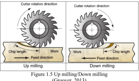
Parameters are values that are selected for the cutting process in order to have a good performance of the machine, low tool wear and good surface finish. Milling operations can be performed depending on the cutter rotation and feed direction. If the cutter rotation is against the feed direction, it is called up-milling. If the cutter rotation moves in the same direction as the feed direction, it is called down milling, as shown in the right side of Figure 1.5. However, the most important characteristic of up milling is that the chip thickness starts very thin and increases during the cutting process. On the contrary, the chip thickness in down milling starts very thick and decreases during the sweeping. Moreover, down milling chips length is shorter than up milling, this means that the cutting tool engages in the workpiece for less time which helps increase the tool life.
Another feature of down milling is that the forces acting over the workpiece tend to hold the workpiece in place as opposed to up milling. In practice, down-milling performs better than up-milling and is preferred for metal machining like titanium (J. Sun & Guo, 2009; A. Li, Zhao, Dong, Wang, & Chen, 2013; Yang & Liu, 2015). In the case of CFRP, J. Y. Sheikh-Ahmad et al. (J. Y. Sheikh-Sheikh-Ahmad, 2009) showed that up-milling has a better surface finish than down-milling as concern delamination and roughness. Therefore, up-milling is preferred for machining CFRPs.
Up milling Down milling
Figure 1.5 Up milling/Down milling (Groover, 2013)
In addition to the sense of the cutter, it is very important to specify the moving speed with which the cutter moves or cutting speed (V) which is normally given in [m/min], see equation (1.1). The cutter feed along the workpiece is called feed rate (fr) and is given in [mm/min] by equation (1.2).
𝑉 = 𝜋. 𝐷. 𝑁 (1.1)
𝑓𝑟 = 𝑓𝑡. 𝑁. 𝑛 = 𝑁. 𝑓 (1.2)
Where:
D is the tool diameter [m], N is the spindle speed [rev/min], f is feed [mm/rev], ft is feed per
tooth [mm/rev-tooth], n is the number of tooth [tooth].
1.2.2 Cutting tools
The selection of cutter material is crucial and depends on the type of material to be machined. Generally, CFRP material is machined using PolyCrystalline Diamond PCD (Lantrip, 2008; El-Hofy et al., 2011; Chatelain et al., 2012 ; H. Wang, Sun, Li, Lu, & Li, 2016; H. Wang, Sun, Zhang, Guo, & Li, 2016), while Titanium alloy is machined using uncoated or coated carbide tool due to its high-impact strength (L. Li, Chang, Wang, Zuo, & He, 2004; J. Sun & Guo, 2009; Palanisamy, Rashid, Brandt, Sun, & Dargusch, 2014; Yujing, Jie, Jianfeng, & Qingchun, 2014; Yang & Liu, 2015).
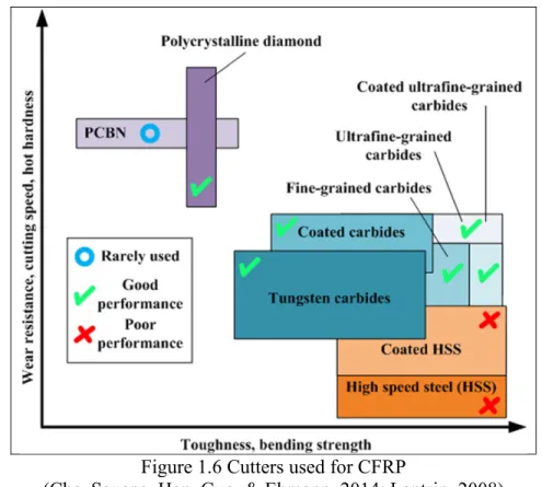
The PolyCrystalline Diamond (PCD) tools are ideal for machining abrasive materials such as CFRP due to their high wear resistance, high toughness and highest hardness of all the cutter materials. However, PCD tools are very sensitive to vibration and are not recommended for ferrous materials or hard metals because of the high solubility of the diamond at high temperatures and its brittleness. Figure 1.6 shows a compilation of the different cutter material used for machining CFRP depending on its wear resistance, cutting speed and toughness performance.
Figure 1.6 Cutters used for CFRP
(Che, Saxena, Han, Guo, & Ehmann, 2014; Lantrip, 2008)
1.2.3 Cutting forces
Another important factor to consider in the machining process is the cutting forces since they can help to understand the behavior of the process and its influence on the temperature, surface quality and tool wear on the cutting tool.
There exist two types of cutting processes: orthogonal and oblique cutting. Orthogonal is the least complex in the interaction between the tool and the chip on the workpiece. If the chip is straight, it is orthogonal. It is when the rake face of cutter produces an angle “rake angle” along with the contact of the cutter and the working piece. As it travels through the surface of the workpiece, a shear plane or shear angle φ is created whose total length of the workpiece is ls.
As it is moved forward, a chip thickness is created hc, the relation between the cut chip thickness
hc, and the uncut chip thickness h is called ratio r= h/hc. The forces which are involved in the
interaction between the cutter and the chip are friction force Fu and the normal force to the tool
In addition to the forces applied by the tool on the chip thickness, normal force to shear plane
Fn and shear force Fs are forces caused as opposition to Fu and Fv by the detachment of the
chip from the workpiece. The 𝛽 is the friction angle between the tool’s rake face and chip and
R is the resultant force or total force, see on the bottom of Figure 1.7. Its equation is given by
(1.3)
𝑅 = 𝐹 + 𝐹 (1.3)
On the other hand, if the cutter has an inclination angle I, there would be a chip flow η. Therefore, a third force is formed in the radial direction Fr component and is called oblique
cutting.
R=Resultant force Fs=Shear force
Fn=Normal force to shear plane
Fu=Friction force
Fv=Normal force to the tool face
Ft=Tangential force (cutting force)
Ff=Feed force or thrust force (axial force)
α=Rake angle φ=Shear angle β=Friction Angle
1.2.3.1 Cutting forces on CFRPs
There are many studies related to the cutting forces and their behavior depending on the fiber orientations and the cutting parameters (cutting speed and feed rate). Ramulu (Ramulu, 1997) studied the behavior of the thrust force in unidirectional and multi-directional graphite/epoxy during the edge trimming. The thrust force increases with the fiber orientation up to 45° and then starts to decrease with the fiber orientation up to 90°. Moreover, Ramulu and Sheikh-Ahmad (Ramulu, 1997; J. Y. Sheikh-Sheikh-Ahmad, 2009) studied the cutting forces in both CFRP and GFRP varying different cutting parameters. The cutting force changes depending on fibers orientation. It increases gradually up to 60° and then increases exponentially up to 90°. After 90°, the cutting force starts to decrease by increasing the fibers orientation. In the case of the thrust force, it remains almost unchanged for fiber orientation up to 90° and then has an oscillatory behavior between 90° up to 180°.
Although the fiber orientation is the most important factor in the cutting forces, the tool geometry such as the rake angle and clearance angle affects the forces as well. In fact, a positive rake angle decreases the cutting and thrust forces, whereas rake angle is not as significant as the fiber orientation (J. Y. Sheikh-Ahmad, 2009; Calzada, Kapoor, DeVor, Samuel, & Srivastava, 2012). In addition to the rake angle, Chatelain and al. (J.-f. Chatelain & I. Zaghbani, 2012) studied the effect of tool geometry on the cutting forces (helix angle β and rake angle
α). Their results revealed that the lower the helix angle, the lower the cutting forces.
1.2.3.2 Cutting forces in orthogonal cutting CFRP/Ti
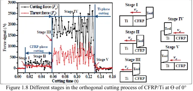
More recently, Jinyang et al. and El Mansori et al. (Jinyang, El Mansori, & El Mansori, 2016; Xu, El Mansori, Chen, & Ren, 2019) are the only ones who have worked in the characterization of cutting forces in the orthogonal cutting of CFRP/Ti stack. However, their stack setups are different from ours since their Ti plaque is on the right and their CFRP plaque on the left or vice-versa, see Figure 1.8. Thus, the cutting force and the thrust force are divided into five stages, depending on the position of the cutter into the workpiece material. In the first and second stages, the cutter starts cutting the CFRP and the forces are stable until the cutter
reaches the third stage (joint between the CFRP and Titanium material). In the third stage, the cutting and thrust forces increase dramatically due to the change of behavior, passing from brittle fracture in CFRP to the plastic deformation in Ti. In the fourth stage, the cutter is completely within the titanium material and the forces are in the steady-state again. Finally, in the fifth stage, the cutting forces decrease after finishing the cutting process. Therefore, forces are highly influenced by the type of material, the cutting force being greater than the thrust force.
Figure 1.8 Different stages in the orthogonal cutting process of CFRP/Ti at Ɵ of 0° , v of 50m/min and f of 0.20 mm/rev
(Jinyang et al., 2016; Xu et al., 2019)
1.2.4 Chip formation in the cutting process of CFRP
The chip formation is the interaction between the cutting tool and the workpiece. In metallic materials, it is generated by continuous plastic deformations, while in the plastic materials, chip formation happens through brittle fracture, which is the case for fiber-reinforced plastic (FRP). Many authors have analyzed the chip formation following FRP machining and there are some theories in the literature although the theory of Wang’s et al. (1995) is the most representative of all of them. There are five different forms of chip formation, which depends on the orientation of the fiber (θ) with the cutter direction and also on the sign of rake angle (positive vs negative), see. Figure 1.9. At fiber orientation of 0° and a positive rake angle, we
observe that a crack begins with the contact of the workpiece and tool, and it moves along with the fiber-matrix interface. Once the cutter moves forward through the workpiece, each fiber is cut separately due to bending and compression stress or delamination, see part a) of Figure 1.9. At fiber orientation of 0° and a negative rake angle, we observe that the continuous movement of the cutter starts to compress the fiber and bends it against its origins. Thus, an in-plane shearing is created, fracturing the fiber-matrix interface. Therefore, the fiber breaks perpendicular due to “buckled” movement, see part b) of Figure 1.9. At fiber orientation of 45° and a positive rake angle, we observe that the crack is provoked by the fracture of the fiber-matrix interface, see part c). At fiber orientation of 0° and a negative rake angle, we observe that the crack is provoked by the compression of the fiber-matrix interface, see part d) of Figure 1.9. At fiber orientation of 90° and a positive rake angle, we observe that the deformation happens when the fiber is crushed and removed with the contact of the tip of the cutter, provoking the fiber fracture that is not in contact with the cutting tool, see part e) of Figure 1.9. At fiber orientation of -45° (135°). and a positive rake angle, we observe that shearing occurs when the fiber is peeled out from the workpiece due to the bending stress below the cutting tool. Additionally, it is characterized by poor surface quality, discontinuous chip, extensive delamination cracking and fiber pull-out (El-Hofy et al., 2011; Chatelain et al., 2012 ).
Figure 1.9 Cutting mechanisms in orthogonal machining of CFRP (D. H. Wang et al., 1995)
1.2.5 Surface roughness
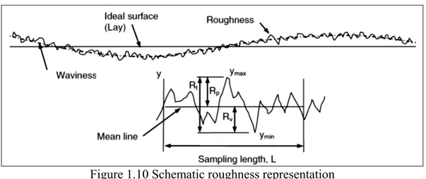
Roughness is defined as the surface waviness in a cross-section area and depends on several factors such as the feed rate magnitude, cutting speed, flank wear, material workpiece, tool geometry, fixture stiffness, coolant, etc. The workpiece surface quality is characterized by lay, waviness and roughness. Theoretically, a lay is an imaginary line describing the contour of the ideal surface, roughness is the height of peaks and valleys of the surface and the waviness is the highest irregularity. The most frequent statistical parameters used to characterize a surface quality are: Ra (arithmetic mean value), Rv (means to the valley height), Rz (ten points average
Figure 1.10 Schematic roughness representation (J. Y. Sheikh-Ahmad, 2009)
For metals, the greater the cutting speed, the lower the surface roughness, but not for titanium alloys. Therefore, the roughness increases with the cutting speed (Nurul Amin, Ismail, & Nor Khairusshima, 2007). In a more recent study, Yang et al. (Yang & Liu, 2015) recommend a low feed per tooth and radial depth of cut and high-cutting speed to reduce the surface roughness.
In the case of CFRPs, the Rz value decreases with increasing the cutting speed and decreasing
the feed rate (Davim, Reis, & António, 2004), the feed rate being the most significant effect. Therefore, the lower the feed rate, the better the surface quality whatever the cutting speed and ply orientation (Chatelain et al., 2012 ). Additionally, the machined surface is not only determined by the cutting parameters but also by the cutter and the fiber direction.
El-Hofy et al. (El-Hofy et al., 2011) analyzed the effects of different cutter materials and the cutting environments such as cold, dry air, concluding that neither the cutter material nor the cutting environment are significant factors. In addition to the cutter material and environment, the cutter geometry influences the roughness parameters of machined CFRPs so that 2 straight flutes or 0 helix angle (β) shows better surface quality than other cutters. Thus, the best surface roughness is at a fiber orientation of 45° and the worst is at -45° (135°) for the most typical roughness profiles (Ra, Rv, Rz) (2012; 2012 ).
Additionally, the CFRPs are prone to delamination, fiber pull-out, loose fiber, matrix cracking, matrix thermal degradation, etc. As a result, Figure 1.11 shows examples of problems during the machining of CFRPs.
Figure 1.11 Example of main problems in machining CFRP (El-Hofy et al., 2011)
1.3 Thermal effects during machining
As shown in the previous sections, most researchers have oriented their research in understanding the cutting parameters of CFRP and Ti plaque. However, few researchers have focused on measuring the cutting temperature during the edge milling cutting process for the CFRP and Ti plaques (Yashiro, Ogawa, & Sasahara, 2013; Lance, Chatelain, & Songmene, 2014; Santiuste, Diaz Alvarez, Soldani, & Miguelez, 2014; H. Wang, Sun, Li, et al., 2016; H. Wang, Sun, Zhang, et al., 2016; J. Sheikh-Ahmad, Almaskari, & Hafeez, 2018). The only study that is closer to the edge milling process of CFRP/Ti stack is an orthogonal study performed by Xu et al. (Xu & El Mansori, 2015, 2016), but their setup is CFRP on the right and Ti on the left or vice versa. Due to the complexity of the process, this type of model cannot fully explain the edge milling of CFRP/Ti6Al4V stack or its thermal distribution. Machining CFRP/Ti6Al4V stack is a challenge due to the different mechanical properties of each material. In the case of Ti6Al4V, it has a low thermal conductivity which can vary from 6 to 9 W/mK (H. B. Wu & Zhang, 2014; Ducobu & Rivière-Lorphèvre, 2016) and high machining temperatures of about 500°C in dry conditions. On the other hand, the CFRPs longitudinal thermal conductivity is 6 W/mK and its transversal thermal conductivity is 0.5 W/mK (Santiuste et al., 2014) adding up a glass transition of 175 °C which is the temperature at which the thermoset epoxy matrix starts to degrade. To the author’s knowledge, there is nothing related to thermal studies in CFRP/Ti.
1.3.1 Temperature measurement methods
In the case of metal machining, there are some techniques to measure the variation of temperature like heat-sensitive painting, liquids, coating, etc. In addition to heat-sensitive methods, the temperature can be measured by contact using thermometers and thermocouples or distance using pyrometers and thermal cameras. In the machining process of CFRP and Ti, thermocouples and thermal cameras are the favorites methods used due to their reliability compared to heat sensitive coating. Generally, the thermal camera is used to measure the temperature in static bodies. Pan et al. and Yashiro et al. (Yashiro et al., 2013; Pan, Kamaruddin, Ding, & Mo, 2014) used this method to measure the cutting temperature both on the tool and workpiece during the end milling surface cutting process. This method was able to measure the temperature at high-speed. However, the thermography was saturated in the case of Ti milling. Thus, it was unable to distinguish the temperature in the cutter-workpiece interface due to the high temperature on the primary shear zone, as shown in the left side of Figure 1.12. In the case of CFRP, the thermography of Yashiro et al. (Yashiro et al., 2013) was not saturated but the temperature could not be observed clearly at a specific point. This is because the area of the cutting process was always hidden by the cutter, reflecting inaccurate temperature. More recently, Sheikh-Ahmad et al. (J. Sheikh-Ahmad et al., 2018) used the black body technique which consists in heating each object to the same temperature with the aim of knowing the emissivity of each object. Therefore, the technique was able to measure the cutting temperature around the cutter, dust bloom and workpiece by the adjustment of the speed frame. The right side of Figure 1.12 shows an example of Sheikh-Ahmad’s thermography camera in the edge milling of CFRP.
Thermography in Ti milling (Pan, Ding, & Mo, 2014)
Thermography in CFRP (J. Sheikh-Ahmad et al., 2018) Figure 1.12 Thermography's examples
Many techniques applied to metal cutting are also applied to CFRP like the thermocouple method (2013). This method uses embedded type K thermocouple in both the cutter and workpiece, the type K (Chromel–Alumel) being the most common for general-purpose. For example, Li et al. (L. Li et al., 2004) measured the cutting temperature on Ti6Al4V shoulder milling, setting the thermocouples in the middle of two blocks. The thermocouple method performed well for the milling process. Nevertheless, the study showed parasite temperature measurements due to the low stiffness and high vibration of the setup.
Yashiro et al. (2013) measured the temperature by embedding thermocouples during the lay-up process of the CFRP, see image 1) of Figure 1.13. On the other hand, Lance et al. (Lance et al., 2014) and J. Sheihk-Ahmad et al. (2018) used the drilled method to embed the thermocouples into the CFRP. Their method consists of drilling and filling the holes with thermal conducting paste with the aim of measuring the temperature on the workpiece. Thus, they inserted the thermocouples as closely as possible from the cutting edge. Image 2) of Figure 1.13 shows an example of the drilling method used by J. Sheihk-Ahmad et al. In the case of Lance et al. (Lance et al., 2014), their thermocouples were not placed at the same distance because of the low stiffness of the micro-drill used in the process, combined with the orthotropic properties of CFRP. Therefore, Lance et al.(2014) registered differences in the temperature of the thermocouples due to the positioning errors during the drilling process of CFRP/Ti6Al4V. Haijin et al., H. Wang et al., and Yujing et al. (Yujing et al., 2014; H. Wang, Sun, Li, et al., 2016; H. Wang, Sun, Zhang, et al., 2016) used a semi-artificial thermocouple to
measure the temperature both in Titanium and in CFRP in separate works. The semi-artificial thermocouple is a handmade thermocouple similar to a metal sheet, calibrated by correlating the voltage to temperature. Even though there is no physical device, the semi-artificial thermocouple is able to measure the cutter temperature, see image 3) of Figure 1.13. Researchers are also interested in measuring the temperature of the cutter. Brinksmeier et al. (2011) stuck thermocouple on the tip of the cutter and Yashiro et al. (2013) correlated the temperature through the differences of voltage between the CFRP and the cutter material. Both methods used wires from the experimental setup to the acquisition data. Thus, it is susceptible to break/unplug during the edge milling cutting process. Although the wired connection has positive results, it needs a special preparation setup to prevent wrong measurements (Brinksmeier et al., 2011; Yashiro et al., 2013). Another method, thanks to technological evolution, to measure the temperature on the cutter tool is through a telemetry system. It transmits the signal from the tool holder to a transducer via a wireless system. As a result, this method uses embedded thermocouple near the cutting point which is connected to the tool holder and is able to measure the temperature in real-time (Kerrigan, Thil, Hewison, & O'Donnell, 2012; Lance et al., 2014; Ghafarizadeh, Lebrun, & Chatelain, 2016; Kerrigan, O’Donnell, & O’Donnell, 2016; Delahaigue, Chatelain, & Lebrun, 2017). Nevertheless, the disadvantage of both methods is that the thermocouple is prone to detach from the cutter. This is a result of the dynamic forces and the friction between pieces during the cutting process.
1). Layout method (Yashiro et al., 2013)
2). Drilling method (J. Sheikh-Ahmad et al., 2018)
3). Semi-artificial method (Yujing et al., 2014)
1.3.2 Influence of cutting temperature in the machining process
The machining process of metallic materials is produced by the plastic deformation, which is converted into heat. The main source of heat is located on the primary shear zone (shear force and normal force to shear plane in Figure 1.7) and the tool-chip interface. High temperatures in the cutting process can be verified by the dark-bluish color of the chips caused by the metal oxidation. In most metals, 90% of the heat is taken away by the chip while 80% of all the heat is concentrated on the cutter edge during the machining of titanium alloy. This is because of its low thermal conductivity (Nouari & Ginting, 2006). For reference purposes only, the thermal conductivity of the Ti6Al4V can vary from 6 to 9 W/mK (H. B. Wu & Zhang, 2014; Ducobu & Rivière-Lorphèvre, 2016). While for steels, it is 50 W/m °K (Nurul Amin et al., 2007). Generally, the machining temperature (Tm) can be represented by the equation (1.4)
𝑇 = 𝑢 𝑣𝑓
𝑘𝑝𝑐 (1.4)
Where v is the cutting speed, f is the feed, u is the specific cutting energy, k is the thermal conductivity, p is the density and c is the specific heat of the workpiece (Shaw, 2004; Pramanik & Littlefair, 2015). It is clear that the temperature is influenced by the cutting parameters and material properties. This means the harder the workpiece material, the higher the cutting temperature. Therefore, it needs higher specific cutting energy and consequently increases the cutting temperature in the case of metals.
1.3.2.1 Influence of cutting parameters on the temperature of Ti
Pan et al. (Pan, Ding, et al., 2014; Pan, Kamaruddin, et al., 2014) studied the effects of the cutting speed, feed rate and axial depth of cut on the cutting forces in end milling. The study shows the forces increase with the cutting speed. However, the feed rate was more statistically significant than the cutting speed and axial depth of cut.
In the literature, most works are focused on understanding the effects of the cutting parameters in the forces. Yujing et al. (Yujing et al., 2014) studied the cutting parameters over the interface workpiece-tool temperature with a semi-artificial thermocouple according to the cutter exit/enter, see the right part of Figure 1.14. The study showed that the cutting speed is the main factor and is more statistically significant than the feed rate, followed by the radial feed and lastly the axial feed, following that order, see the right part of Figure 1.14.
Thermocouple recording method Cutting parameters influence Figure 1.14 An experimental investigation in milling Ti6Al4V
(Yujing et al., 2014)
1.3.2.2 Influence of cutting parameters on the temperature of CFRP
As it was mentioned at the beginning of this chapter, a few researchers focused on understanding the thermal effects on CFRP. Yashiro et al. (2013) studied the influence of the cutting parameters over the temperature, keeping the feed per tooth as a constant through the development of the experiments. Their study revealed that the lower cutter speed, the higher the temperature in the workpiece. As a result, they suggested a high-cutting speed of up to 300 m/min to decrease the workpiece temperature. This is because using these cutting speed values, the CFRP plaque did not show matrix thermal damage looking through the Scanning Electron Microscope (SEM). Therefore, the temperature was below 180°C which is the glass transition temperature for thermoset matrix resin. However, it should be mentioned that type K
thermocouple was very sensitive to the distance and it was registered a temperature difference of about 54°C between the distance of the cutting edge and thermocouple tip (Δl) equal 0.6 and
Δl equal 0.3 mm from the cutter edge, keeping the same cutting conditions.
Haijin et al. (H. Wang, Sun, Li, et al., 2016) studied the effects of cutting parameters on the force and temperature. The study found that the greater the cutting speed, the lower the forces. However, this is opposite to the temperature since the growth of temperature is notably higher with the increase in the cutting speed. In addition to the cutting speed, the analysis also focused on the effects of the feed rate and the radial depth of cut and their effects on the forces and the temperature. By increasing the magnitude of the feed rate, there is a significant growth in the forces. However, this effect is much less significant in the temperature increase. For the radial depth of cut, neither force nor temperature is influenced by this parameter. Therefore, in order to keep a low temperature on the workpiece and machine efficiency, it is recommended setting up a low cutting speed, low feed rate, and high radial depth of cut. Thus, the cutting speed is the factor which influences the temperature and feed rate is the factor which influences the cutting forces. In the case of the radial depth of cut, this has little influence both on temperature and forces.
Kerrigan et al. (Kerrigan et al., 2016) measured the cutter temperature using an embedded K thermocouple, through a Wireless Tool Holder module system and infrared camera for the workpiece. Their results showed that feed rate is the main factor effect, followed by the axial depth of cut and finally the workpiece location on the cutter axis for the cutting forces. On the other hand, the temperature on the cutting tool showed a different behavior from forces. The axial depth of cut is the most significant factor, followed by the central workpiece location on the cutter axis while the feed rate is the least significant factor. It should be mentioned that although the study used a thermal camera to measure the temperature of the workpiece, there is no information about their results.
1.3.3 Thermal aspects during machining CFRP
Machining CFRPs materials can provoke different cutting defects both in the fibers and matrix. The most common defects in CFRP are fiber pull out, delamination, matrix cracking and
thermal damage. In the case of thermal damage, it occurs when the temperature inside the CFRP exceeds the thermoset glass transition temperature (Tg). This temperature is about 175 °C ±10 °C for the epoxy matrices. Additionally, the thermoset matrix has very poor thermal conductivity and is about 0.21 W/mK (Khashaba, 2013) to 0.35 W/mK (Nomura & Haji-Sheikh, 2018). The thermal conductivity of the composite (fiber + matrix) can be calculated by using the rule of mixture, equation (1.5).
𝐾 = 𝐾 𝑉 + 𝐾 (1 − 𝑉 ) (1.5)
Where 𝐾 and 𝐾 are the thermal conductivity of the matrix and fiber and 𝑉 is the fiber volume fraction. Therefore, the CFRP’s longitudinal thermal conductivity is 6 W/mK and its transversal thermal conductivity is 0.5 W/mK (Santiuste et al., 2014), which are very low compared to steel at 50 W/mK.
H. Wang et al. (2016) studied fiber orientation on thermal effects during the milling process by using a semi-artificial thermocouple. The study found that the cutting forces start to rise and then to decrease with the increase of the cutting speed at fiber orientation θ of 0°, 45°, 90° and 135°, see the left side of Figure 1.15. This is because the heat generated by the cutter in the cutting zone softens the epoxy matrix. As a result, the amount of energy transferred into the CFRP workpiece increase too. Similar results were found by Yashiro et al. (2013). The right part of Figure 1.15 shows that cutting temperature in the 45° fiber orientation is always the lowest while the 135° fiber orientation is always the highest no matter how fast the cutting speed is.
Effects of cutting forces vs θ Effects of temperature vs θ Figure 1.15 Analysis of thermal effects on the fiber orientation
(H. Wang, Sun, Zhang, et al., 2016) This can be explained by using the heat transfer equation:
∆𝑇 = 𝑞
𝜌𝑐(4𝜋𝑎𝑣𝑋) / . 𝑒𝑥𝑝 −
𝑣𝑦
4𝑎𝑋 (1.6)
Where ∆𝑇 is the temperature increase, qs is the heat source; c is the specific heat capacity, ρ is
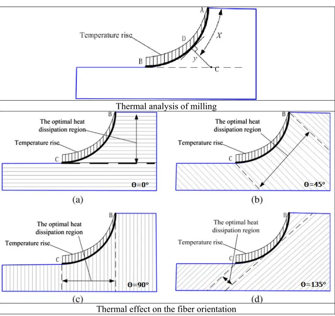
the heat medium density; λ is the thermal conductivity, α= λ/ρc is the heat dissipation rate, ν is the cutting speed; y is the shortest distance from the heat source to the reference point and X is the moving distance of the cutter, X=νt. By solving equation (1.6) in terms of partial derivative (δΔT/δα), the temperature can decrease by increasing the heat dissipation rate 2αt>y. This means that the thermal build-up and the rise in temperature are due to the low thermal conductivity of the material when the monitoring position is very near to the surface of the cut. Thus, the thermal conductivity for each fiber orientation is different because the heat dissipation rate α changes according to θ, as shown in Figure 1.16. As a result, the temperature rises from point A to B.
Thermal analysis of milling
Thermal effect on the fiber orientation
Figure 1.16 Thermal analysis in CFRP milling for different fiber orientation (H. Wang, Sun, Zhang, et al., 2016)
In the case of unidirectional CFRP, the thermal conductivity λ is described by equation (1.7):
𝜆 , = 𝜆 , cos 𝜃 + 𝜆 , sin 𝜃 (1.7)
Where θ is the fiber orientation with respect to cutter movement, 𝜆 , is composite thermal conductivity, 𝜆 , is the thermal conductivity in a parallel orientation with the fiber, 𝜆 , is the thermal conductivity in a transverse orientation direction with the fiber. It should be noted that 𝜆 , are 10 times greater than 𝜆 , . The highest heat dissipation is along the 45° fiber orientation.
This is because the heat dissipation region is the same for all angles and it is fixed by the tool radius. Thus, heat dissipates more in the 45° direction since its thermal conductivity is higher in the fiber direction than in the transverse direction following the cutter path from B to C as compared to 0° and 90°, as shown in the right side of Figure 1.16. In the case of 0° and 90°, the heat dissipation is the same for both of them. Nevertheless, the fiber breakage due to machining at 0° is different than for the 90° fiber orientation. Thus, the surface finishing is much better in the case of 0° which is totally covered with epoxy. However, in the case of 90°, the fiber is exposed by the cutting fracture. Finally, the worst case of heat flow is given by 135° because the heat flows almost perpendicular to fibers for all the cutter path (from B to C). It also has the worst surface finish and roughness of all the fiber orientations. In addition, Figure 1.17 (region 1 to 3) shows the carbon fibers and mini-grooves due to thermal damage. This is as a result of the heat concentration in the workpiece, resulting in both mechanical and matrix thermal damage when the Tg is exceeded.
Figure 1.17 Example of thermal damage observed by SEM (H. Wang et al., 2016)
1.3.4 Heat flux in CFRP plaque
Sheikh-Ahmad et al. (2018) studied the heat flux surrounding the workpiece, chip and tool by using thermographs. The temperature was measured every 3 seconds on the cutter and chip, combining an experimental and numerical study. Additionally, they tested different tool materials and geometries during the edge trimming of CFRP plaque. In order to avoid saturated images, the black body technique was used with the aim of knowing the emissivity of each object. The study showed that the hottest cutting zone was located in the cutter registering temperatures from 220 to 250°C. Then it is followed by the chip temperature from 160 to 220°C and lastly, the workpiece registered the coldest temperature of about 60°C due to the heat dissipation through the chip. The study also shows that the helix angle has an effect on the temperature. Therefore, the smaller the helix flux of the cutter tool, the higher the temperature on the cutter since the chip cannot be easily evacuated, blocking all the heat flow. Statistically speaking, neither the cutting speed nor the feed rate was statistically significant in the heat exchange on the cutter. On the other hand, the feed is statistically significant on the workpiece temperature. Thus, the higher the feed rate, the lower the temperature on the workpiece. This result is contradictory to other works (Yashiro et al., 2013; H. Wang, Sun, Li, et al., 2016) in which the main factor is the cutting speed. Analytically, the heat flux in the machining process can be calculated by using an equation of energy balance (1.8):
𝑄 = 𝑄 + 𝑄 + 𝑄 (1.8)
Where 𝑄 is the mechanical power transformed to heat, 𝑄 is heat conducted by the tool, 𝑄 is heat conducted by the workpiece, 𝑄 is heat conducted by the chip. Hence, equation (1.8) can also be represented by equation (1.9):
𝑄 = 𝑃 𝜂 𝑄 = 𝑞 . 𝐴
𝑄 = 𝑞 . 𝐴