Science Arts & Métiers (SAM)
is an open access repository that collects the work of Arts et Métiers Institute of
Technology researchers and makes it freely available over the web where possible.
This is an author-deposited version published in: https://sam.ensam.eu Handle ID: .http://hdl.handle.net/10985/8708
To cite this version :
EL HOUSSIN EL BOUCHIKHI, Vincent CHOQUEUSE, Mohamed BENBOUZID, Jean-Frederic CHARPENTIER, Georges BARAKAT - A Comparative Study of Time-Frequency Representations for Fault Detection in Wind Turbine - In: IECON 2011-37th Annual Conference on IEEE Industrial Electronics Society, Australia, 2011-11 - 37th Annual Conference on IEEE Industrial Electronics Society - 2011
Any correspondence concerning this service should be sent to the repository Administrator : [email protected]
A Comparative Study of Time-Frequency
Representations for Fault Detection in Wind Turbine
El.H. Bouchikhi, V. Choqueuse, M.E.H. Benbouzid, J.F. Charpentier and G. Barakat
Abstract—To reduce the cost of wind energy, minimization
and prediction of maintenance operations in wind turbine is of key importance. In variable speed turbine generator, advanced signal processing tools are required to detect and diagnose the generator faults from the stator current. To detect a fault in non-stationary conditions, previous studies have investigated the use of time-frequency techniques such as the Spectrogram, the Wavelet transform, the Wigner-Ville representation and the Hilbert-Huang transform. In this paper, these techniques are presented and compared for broken-rotor bar detection in squirrel-cage generators. The comparison is based on several criteria such as the computational complexity, the readability of the representation and the easiness of interpretation.
Index Terms—Wind turbine, fault detection, broken-rotor
bars, signal processing, time-frequency representations.
I. INTRODUCTION
Wind energy is the fastest growing energy source in the world and it is expected to remain so for the foreseeable future. To reduce the cost of wind energy, there is a need to improve the wind turbines availability and to reduce the maintenance cost [1]. This need is even more important in the offshore context due to the aggressive environmental conditions. To answer this need, condition monitoring systems based on current, vibration, oil and temperature analysis have been developed. As compared to other techniques, generator current analysis has several advantages since sensors are low-cost and easy to install. Furthermore, the fault-detection techniques based on stator-current, initially developed for electric motor [2], can be easily adapted to wind turbine generator.
In the field of electric motor, many signal processing techniques have been employed to detect a fault from the stator current. Most of them perform spectral analysis, such as Fourier or MUSIC techniques. Although these techniques ex-hibit good results in stationary conditions, they are badly suited for wind turbines since the environment is predominantly non-stationary due to transient or variable speed conditions. In non-stationary conditions, fault detection is usually performed by using sophisticated approaches, such as time-frequency or time-scale representations [3]. These approaches include the
El.H. Bouchikhi, V. Choqueuse and M.E.H. Benbouzid are with the Labo-ratoire Brestois de M´ecanique et des Syst`emes (LBMS EA 4325), University of Brest, Rue de Kergoat, CS 93837, 29238 Brest Cedex 03, France (e-mail: [email protected],[email protected] [email protected]).
J. F. Charpentier is with the French Naval Academy Research Institute (IRENav EA 3634), French Naval Academy, 29240 Brest Cedex 9, France (e-mail: [email protected]).
G. Barakat is with the Electrical Engineering Department, GREAH, Uni-versity of Le Havre, 76600 France (e-mail: [email protected]).
Short-Time Fourier Transform (STFT) [4]–[8], the Continuous Wavelet Transform (CWT) [1], [9], [10], the Wigner-Ville and other quadratic Distributions [6], [11]–[15] and the Hilbert-Huang Transform (HHT) [15]–[17]. However, despite of the rich literature, the choice of a particular representation is not an easy task since several criteria must be taken into account. In this study, several time-frequency representations are considered for fault detection and are applied to a squirrel-cage wind-turbine. These representations are compared according to their computational complexity, readability of the representa-tion and easiness of interpretarepresenta-tion. This paper is organized as follows: section II describes the generator stator current model, section III presents the most commonly used time-frequency representations and section IV reports on their performances for broken rotor bar faults detection in transient condition.
II. COUPLEDMAGNETICCIRCUITGENERATORMODEL
(CMCM)
This section describes the generator model used to simulate the stator current under healthy and faulty conditions. For most of the faults, the harmonic contents of the stator current can be approximated using linear models of the machine such as the Coupled Magnetic Circuit Method (CMCM) [18]. This approach is based on the analytical equations of the induction machine. All parameters are calculated from the actual ge-ometry and winding layout of the machines rather than from transformed or equivalent variables. This analysis is based on the following assumptions: i) infinite iron permeability, ii) non conductive magnetic circuit, iii) no inter-bars currents and iv) negligible saturation. The equations system governing the operation of induction machine in the phase space is given by (1). ⎧ ⎨ ⎩ 𝑑 𝑑𝑡[𝐼] = −[𝐿]−1 ( [𝑇 ] + Ω 𝑑 𝑑𝜃𝑀[𝐿] ) [𝐼] + [𝐿]−1[𝑉 ] 𝑑 𝑑𝑡𝜔 = 2𝐽1[𝐼]𝑇 ( 𝑑 𝑑𝜃𝑀[𝐿] ) [𝐼] −𝑓𝐽Ω − 1 𝐽Γ𝐿 𝑑 𝑑𝑡𝜃𝑚= 𝜔 (1)
The expression of the inductance matrix [L] of the induction machine can be extracted from the flux or from the magnetic energy stored on the air-gap. The computation of this matrix containing all magnetizing and mutual inductances is the key to a successful simulation of the squirrel cage induction machine. In order to model the machine in the case of broken bar, the equivalent circuit is opened and the inductances matrix are recalculated.
III. FAULT DETECTION BASED ONTIME-FREQUENCY
ANALYSIS
The following subsections describes several techniques for representing time-frequency content of the stator current,𝑥(𝑡). A. Short-Time Fourier Transform (STFT)
The Short-Time Fourier Transform (STFT) is based on the assumption that the signal is quasi-stationary over a short period of time. It is composed of two steps: first, the signal is divided into time segments and then, the spectrum of each segment is obtained via the Fourier Transform. This procedure, called the STFT, leads to a 3D representation which displays the frequency content over time.
Mathematically, the Short-Time Fourier Transform can be expressed as [3]
𝑆𝑥(𝑡, 𝑓) =
∫ ∞
−∞𝑥(𝜏)ℎ
∗(𝜏 − 𝑡)𝑒−2𝑗𝜋𝑓𝜏𝑑𝜏 (2)
whereℎ(𝑡) is a time-window centered in 𝑡 = 0 which is used to extract the time segments. The STFT is a linear transform i.e.𝑆𝑥+𝑦(𝑡, 𝑓) = 𝑆𝑥(𝑡, 𝑓) + 𝑆𝑦(𝑡, 𝑓). To obtain an admissible representation, ℎ(𝑡) must have unit energy i.e.
∫ ∞
−∞∣ℎ(𝑡)∣
2𝑑𝑡 = 1 (3)
A classical choice for ℎ(𝑡) is the rectangular, Hanning, Hamming or Gaussian window. The length of the window ℎ(𝑡) determines the time and frequency resolution of the representation. This resolution is kept constant over the time-frequency plane. A short window leads to a representation which is fine in time but coarse in the the frequency domain. Conversely, a long window leads to a representation which is coarse in time but fine in the the frequency domain. This trade-off is formalized by the Heisenberg-Gabor uncertainty principle [3].
B. Continuous Wavelet Transform (CWT)
The Continuous Wavelet Transform (CWT) is obtained by breaking up the signal into shifted and scaled versions of a mother wavelet.
Mathematically, the Continuous Wavelet Transform can be expressed as [3] 𝑇𝑥(𝑡, 𝑎) = √1𝑎 ∫ ∞ −∞𝑥(𝜏)𝑤 ∗(𝜏 − 𝑡 𝑎 ) 𝑑𝜏 (4)
where𝑎 is the scale and 𝑤(𝑡) is the mother wavelet. The CWT is a linear transform i.e.𝑇𝑥+𝑦(𝑡, 𝑓) = 𝑇𝑥(𝑡, 𝑓) + 𝑇𝑦(𝑡, 𝑓). To obtain an admissible representation,𝑤(𝑡) must have zero-mean
i.e. ∫ ∞
−∞𝑤(𝑡)𝑑𝑡 = 0 (5)
A classical choice for 𝑤(𝑡) is the Mexican-Hat, Morlet or Daubechies wavelets. Rigorously speaking, the CWT leads to a scale representation since it displays the signal time-evolution at different scales. However, there is a direct link between scale and frequency. Indeed, if the central frequency
of the mother wavelet 𝑤(𝑡) is 𝑓0, the scale 𝑎 corresponds to the frequency 𝑓 = 𝑓0/𝑎. As opposed to the STFT, the
CWT is a multi-resolution technique which favors the time-resolution at high-frequencies and the frequency-time-resolution at low-frequencies.
C. Wigner-Ville and other quadratic distributions
As opposed to the previous techniques, which focus on the decomposition of the signal itself, the Wigner-Ville distribu-tion (WVD) focuses on the decomposidistribu-tion of the signal energy in the time-frequency plane.
Mathematically, the WVD can be expressed as [3] 𝑊𝑥,𝑥(𝑡, 𝑓) = ∫ ∞ −∞𝑥 ( 𝑡 + 𝜏2)𝑥∗(𝑡 − 𝜏 2 ) 𝑒−2𝑗𝜋𝑓𝜏𝑑𝜏 (6)
The time-frequency resolution of WVD is not constrained by the Heisenberg Gabor inequality. However, the WVD is non-linear since 𝑊(𝑥+𝑦),(𝑥+𝑦)(𝑡, 𝑓) ∕= 𝑊𝑥,𝑥(𝑡, 𝑓) + 𝑊𝑦,𝑦(𝑡, 𝑓). This non-linearity is responsible for the introduction of inter-ference terms. These interinter-ference terms can render the time-frequency representation difficult to interpret. To reduce inter-ference terms, the analytical signal of𝑥(𝑡) is usually employed instead of the signal itself. Furthermore, several authors have proposed extensions of the WVD for interference reduction at the expense of reduced resolution. These extensions have been unified by the Cohen’s class of time-frequency distributions [19]. This class is given by
𝐶𝜙 𝑥,𝑥(𝑡, 𝑓) = ∫∫∫ R3𝜙(𝜉, 𝜏)𝑒 2𝑗𝜋𝜉(𝑠−𝑡) × 𝑥(𝑠 +𝜏2)𝑥∗(𝑠 −𝜏 2 ) 𝑒−2𝑗𝜋𝑓𝜏𝑑𝜉𝑑𝑠𝑑𝜏(7)
where 𝜙(𝜉, 𝜏) is the kernel of the distribution. The Cohen’s class includes many commonly used time-frequency distribu-tions such as the Pseudo Wigner-Ville, the Choi-Williams and the Zhao-Atlas-Marks Distributions.
D. Hilbert-Huang Transform
The Hilbert-Huang Transform is a nonlinear technique which extract the time-frequency content of a non-stationary signal. This technique is composed of 2 steps: i) first, the signal is decomposed into a sum of amplitude- and frequency- modulated sine waves using an Empirical Mode Decomposition, and then ii) the instantaneous amplitude and frequency are extracted using a demodulation technique. Finally the time-frequency representation is obtained by displaying the time evolution of the instantaneous amplitude and frequency for each sine wave.
1) Empirical Mode Decomposition: The Empirical Mode Decomposition (EMD) has been originally proposed by Huang [20]. As opposed to the previous techniques, the EMD is essentially defined by an algorithm and does not admit an analytical definition [21]. The algorithm is described by the following steps [20]:
∙ Identification of all extrema of 𝑥(𝑡)
∙ Interpolation between minimal (resp. maxima) ending up with some envelope𝑒𝑚𝑖𝑛(𝑡) (resp. 𝑒𝑚𝑎𝑥(𝑡)).
∙ computation of the mean:
𝑚(𝑡) = 𝑒𝑚𝑖𝑛(𝑡) + 𝑒2 𝑚𝑎𝑥(𝑡) (8)
∙ extraction of the detail:
𝑑(𝑡) = 𝑥(𝑡) − 𝑚(𝑡) (9)
∙ Iteration on the residual𝑚(𝑡).
In practice, this algorithm has to be refined by a shifting process until𝑑(𝑡) can be considered as zero-mean. After this procedure, the detail 𝑑(𝑡) corresponds to an amplitude- and frequency- modulated (AM/FM) sine wave called Intrinsic Mode Function (IMF). By iterating the algorithm on the residual𝑚(𝑡), the EMD extracts several IMFs until a stopping criterion is reached.
2) Instantaneous Amplitude (IA) and frequency (IF) extrac-tion: The IA and IF of each sine wave can be extracted using a demodulation technique. To achieve this task, a popular technique is based on the Hilbert Transform. Let us denote 𝑥𝑘(𝑡) the 𝑘𝑡ℎ IMF, the analytical signal of 𝑥𝑘(𝑡), denoted 𝑧𝑘(𝑡), is defined as
𝑧𝑘(𝑡) = 𝑥𝑘(𝑡) + 𝑗ℋ[𝑥𝑘(𝑡)] (10)
where ℋ[.] denotes the Hilbert Transform. The instantaneous amplitude and frequency can be extracted from the analytical signal as follows
𝑎𝑘(𝑡) = ∣𝑧𝑘(𝑡)∣ (11)
𝑓𝑘(𝑡) = 2𝜋1 𝑑𝑎𝑟𝑔[𝑧𝑑𝑡𝑘(𝑡)] (12)
where ∣.∣ and 𝑎𝑟𝑔[.] denote respectively the modulus and the argument of a complex number. Finally, the time-frequency representation is obtained by displaying the evolution of𝑎𝑘(𝑡) and𝑓𝑘(𝑡) for each IMF in the time-frequency plane.
IV. SIMULATIONRESULTS
In this section, we compare several time-frequency repre-sentations for the detection of broken rotor bar faults. The stator current have been simulated using a coupled magnetic circuit method (CMCM). CMCM has been performed with a healthy generator and a faulty one with two broken bars. The stator-current signals have been simulated during 1 second at a1𝑘𝐻𝑧 sampling frequency. Signals have been analyzed with the following time-frequency representations:
∙ A Short-Time Fourier Transform with a Hamming win-dow ℎ(𝑡) of 256 samples length.
∙ A Continuous Wavelet Transform with a Morlet mother wavelet𝑤(𝑡).
∙ The Pseudo Wigner distribution computed from the ana-lytical signal.
∙ The Hilbert-Huang transform.
All these representations, except the last one, have been im-plemented using the Time-Frequency Toolbox for Matlab [22]. The HHT has been implemented using the G. Rilling’s sub-routines for Matlab. The following subsections compare the computational complexity and the readability of these time-frequency representations.
A. Computational Complexity
Matlab programs were run offline on a Pentium dual core PC at 1.6 Ghz with 1 Go of RAM. The computational requirement of each algorithm is reported in Table I. This table shows that the CWT is the most computationally demanding technique as compared to the STFT, the Pseudo WV and the HHT. By comparing the computational time with the length of the recorded signal (1s), we can observe that the STFT and the Pseudo WV are the only two candidates that could be implemented in real-time under our configuration. In particular, the STFT, which has the lowest computational cost, is an attractive technique since it can be efficiently implemented using Fast Fourier Transform.
TABLE I
COMPUTATIONALCOMPLEXITY
Representation (Average) Computational time STFT 0.2 s
CWT 25.2 s Pseudo WV 0.4s
HHT 1.57s
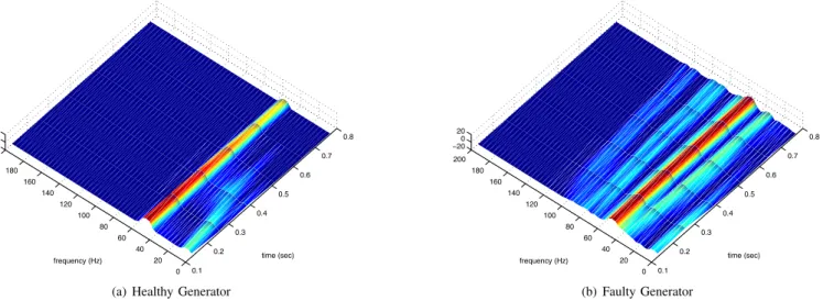
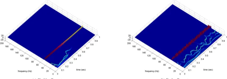
B. Representation readability and easiness of interpretation Figs.1 to 4 display the time-frequency representations for healthy and faulty generators. For each representation, we can observe a strong difference between the time-frequency representations of healthy and faulty generators. For the STFT, CWT and Pseudo WV, the faulty generator exhibits singu-lar time-varying components at frequencies below 40Hz and above 70Hz. For the HHT, the fault generator introduces frequency modulation of the 50Hz component and some components below 30Hz.
Concerning the time-frequency resolution, figures show that the resolution of the STFT and CWT is lower than the one of the other representations. Indeed, as opposed to the Pseudo WV and HHT, the resolution of the STFT and CWT are limited by the Heisenberg-Gabor uncertainty principle. This constraint makes the STFT and CWT bad-suited for analysis of signals with rapidly evolving frequency content.
We can observe that the readability of the Pseudo-WV and HHT is lower than the one of the STFT and CWT. First, the Pseudo-WV exhibits interference terms which can render difficult the interpretation. Then, the HHT presents sev-eral low-frequency components which are difficult to analyse (below 30Hz). Even if these components have low-energy, they negatively impact the readability of the time-frequency representation.
0.1 0.2 0.3 0.4 0.5 0.6 0.7 0.8 0 20 40 60 80 100 120 140 160 180 200 −20 0 20 time (sec) frequency (Hz)
(a) Healthy Generator
0.1 0.2 0.3 0.4 0.5 0.6 0.7 0.8 0 20 40 60 80 100 120 140 160 180 200 −20 0 20 time (sec) frequency (Hz) (b) Faulty Generator Fig. 1. Modulus of the STFT for a) healthy and b) faulty generator.
(a) Healthy Generator (b) Faulty Generator Fig. 2. Modulus of the Continuous Wavelet Transform for a) healthy and b) faulty generator.
(a) Healthy Generator (b) Faulty Generator Fig. 3. Pseudo Wigner-Ville Distribution for a) healthy and b) faulty generator.
(a) Healthy Generator (b) Faulty Generator Fig. 4. Hilbert Huang Transform for a) healthy and b) faulty generator.
V. CONCLUSION
This study has presented a comparison of several time-frequency representations for broken rotor bars fault detec-tion in a squirrel-cage wind turbine generator. The Short-Time Fourier, the Continuous Wavelet Transform, the Pseudo Wigner-Ville and the Hilbert-Huang transform have been compared according to their computational complexity, time-frequency resolutions and readability. Simulation results have showed that each technique allows detection of the broken rotor bars fault. For our simulations, Table II reports the advantages and disadvantages of each representation. This table shows that the choice of a particular representation depends on the user’s constraints and priorities in terms of computation complexity and easiness of interpretation.
TABLE II
COMPARISON OF SEVERAL TIME-FREQUENCY REPRESENTATIONS
Representation Computational Cost Resolution Readability STFT ++ - - ++ CWT - - + ++ Pseudo WV + +
-HHT - ++ +
REFERENCES
[1] W. Yang, P. Tavner, C. Crabtreee, and M. Wilkinson, “Cost-effective condition monitoring for wind turbines,” IEEE Transactions on
Indus-trial Electronics, vol. 57, no. 1, pp. 263–271, 2010.
[2] M. Benbouzid, “A review of induction motors signature analysis as a medium for faults detection,” IEEE Transactions on Industrial
Electron-ics, vol. 47, no. 5, pp. 984–993, 2000.
[3] P. Flandrin, Time-frequency/time-scale analysis. Academoc Press, 1998. [4] B. Yazici and G. Kliman, “An adaptive statistical time-frequency method for detection of broken bars and bearing faults in motors using stator current,” IEEE Transactions on Industry Applications, vol. 35, no. 2, pp. 442–452, 1999.
[5] M. Benbouzid and G. Kliman, “What stator current processing based technique to use for induction motor rotor faults diagnosis?” IEEE
Transactions on Energy Conversion, vol. 18, no. 2, pp. 238–244, 2003.
[6] S. Rajagopalan, J. Aller, J. A. Restrepo, T. Habetler, and R. Harley, “Detection of rotor faults in brushless dc motors operating under nonstationary conditions,” IEEE Transactions on Industry Applications, vol. 42, no. 6, 2006.
[7] J.Cusido, L. Romeral, J. Ortega, J. Rosero, and A. Espinosa, “Fault detection in induction machines using power spectral density in wavelet decomposition,” IEEE Transactions on Industrial Electronics, vol. 55, no. 2, pp. 633–643, 2008.
[8] S. Kia, H. Henao, and G. Capolino, “Torsional vibration assessment using induction machine electromagnetic torque estimation,” IEEE
Transactions on Industrial Electronics, vol. 57, no. 1, pp. 209–219, 2010.
[9] S. Rajagopalan, J. Aller, J. A. Restrepo, T. Habetler, and R. Harley, “Analytica-wavelet-ridge-based detection of dynamic eccentricity in brushless direct current (bldc) motors functioning under dynamic oper-ating conditions,” IEEE Transactions on Industrial Electronics, vol. 54, no. 3, 2007.
[10] J.Pons-Llinares, J. Antonino-Daviu, M. Riera-Guasp, M. Pineda-Sanchez, and V. Climente-Alarcon, “Induction motor diagnosis based on a transient current analytic wavelet transform via frequency b-splines,”
IEEE Transactions on Industrial Electronics, vol. 58, no. 5, pp. 1530–
1544, 2011.
[11] M. Blodt, M. Chabert, J. Regnier, and J. Faucher, “Mechanical load fault detection in induction motors by stator current time-frequency analysis,”
IEEE Transactions on Industry Applications, vol. 42, no. 6, pp. 1454–
1463, 2006.
[12] M. Blodt, D. Bonacci, J. Regnier, M. Chabert, and J. Faucher, “On-line monitoring of mechanical faults in variable-speed induction motor drives using the wigner distribution,” IEEE Transactions on Industrial
Electronics, vol. 55, no. 2, pp. 522–533, 2008.
[13] S. Rajagopalan, J. A. Restrepo, J. Aller, T. Habetler, and R. Harley, “Nonstationary motor fault detection using recent quadratic time-frequency representations,” IEEE Transactions on Industry Applications, vol. 44, no. 3, 2008.
[14] M. Blodt, J. Regnier, and J. Faucher, “Distinguishing load torque oscillations and eccentricity faults in induction motors using stator cur-rent wigner distributions,” IEEE Transactions on Industry Applications, vol. 45, no. 6, pp. 1991–2000, 2009.
[15] J. Rosero, L. Romeral, J. Ortega, and E. Rosero, “Short-circuit detection by means of empirical mode decomposition and wigner-ville distribution for pmsm running under dynamic condition,” IEEE Transactions on
Industrial Electronics, vol. 56, no. 11, pp. 4534–4547, 2009.
[16] J. Antonino-Daviu, M. Riera-Guasp, M. Pineda-Sanchez, and R. Prez, “A critical comparison between DWT and Hilbert-Huang-based methods for the diagnosis of rotor bar failures in induction machines,” IEEE
Transactions on Industry Applications, vol. 45, no. 5, 2009.
[17] A. Espinosa, J. Rosero, J. Cusido, L. Romeral, and J. Ortega, “Fault detection by means of hilbert-huang transform of the stator current in a
pmsm with demagnetization,” IEEE Transactions on Energy Conversion, vol. 25, no. 2, pp. 312–318, 2010.
[18] G. Houdouin, G. Barakat, B. Dakyo, E. Destobbeleer, and C. Nichita, “A coupled magnetic circuit based global method for the simulation of squirrel cage induction machines under rotor and stator faults,” in
Proceedings of ELECTRIMACS’02, Montreal, Canada, 2002.
[19] L. Cohen, “Time-frequency distributions: A review,” Proceedings of the
IEEE, vol. 77, no. 7, pp. 941–981, 1989.
[20] N. Huang, Z. Shen, S. Long, M. Wu, H. Shih, Q. Zheng, N. Yen, C. Tung, and H. Liu, “The empirical mode decomposition and hilbert spectrum for nonlinear and nonstationary time series analysis,” Proc.
Roy. Soc. London, vol. 454, p. 903995, 1998.
[21] G. Rilling, P. Flandrin, and P. Goncalvs, “On empirical mode decom-position and its algorithms,” in IEEE-EURASIP Workshop on Nonlinear
Signal and Image Processing, Grado, Italia, 2003.
[22] F. Auger, P. Flandrin, P. Goncalves, and O. Lemoine, “Time-frequency toolbox, for use with matlab,” CNRS, GDR ISIS, Tech. Rep., 1997.
3589