Science Arts & Métiers (SAM)
is an open access repository that collects the work of Arts et Métiers Institute of
Technology researchers and makes it freely available over the web where possible.
This is an author-deposited version published in: https://sam.ensam.eu Handle ID: .http://hdl.handle.net/10985/10783
To cite this version :
Shabab SAMIMI, François GRUSON, Philippe DELARUE, Xavier GUILLAUD - Synthesis of different types of energy based controller for a Modular Multilevel Converter integrated in a HVDC link - In: ACDC2015, Royaume-Uni, 2015-02-10 - ACDC2015 - 2015
Synthesis of different types of energy based controller for a
Modular Multilevel Converter integrated in a HVDC link
S. Samimi
1, F. Gruson
2, P. Delarue
3, X. Guillaud
11 L2EP, Ecole Centrale de Lille, 59650 Villeneuve d’Ascq, France [email protected],[email protected], 2 L2EP, Arts et Métiers ParisTech, 8,Bd Louis XIV, 59046 Lille, France [email protected]
3L2EP, Lille 1 University, 59655 Villeneuve d’Ascq, France
Keywords: Modular Multilevel Converter (MMC), Converter
current and power controls, HVDC,DC bus control, Electromagnetic Transients program (EMTP),
Abstract
Modular Multilevel Converters are becoming increasingly popular with the development of HVDC connection and, in the future, Multi Terminal DC grid. A lot of publications have been published about this topology these last years since it was first proposed. Few of them are addressing explicitly the 2 different roles that are held by this converter in a HVDC link: controlling the power or controlling the DC voltage level. Moreover, for a given function, different ways of controlling this converter may be considered. This paper proposes an overview of the different solutions for controlling the MMC and proposes a methodology to synthesize the control architecture.
1 Introduction
HVDC link are expected to a large development due to the increasing need to transmit electrical power. Thyristor technology is still used for very large application (up to 7 GW) but transistor technology is becoming more and more familiar. The first big project in this field is the Cross Sound Cable (330 MW, 150 kV) between Long Island and the American continent was installed in 2002 using a 3-level converter. Because of the high voltage levels, a very large number of transistors is placed in series. However, this large stack of series switches needs to have nearly identical parameters and synchronized ignition to avoid excessive stresses on single components during switching actions [1] The high frequency switching operation of the PWM (≈ 1 kHz) was also responsible for significant losses.
The Modular Multilevel Converter has been developed to overcome the aforementioned problems and offers several advantages over previous voltage–source converter (VSC) technologies [2], [3]. Indeed, it is not an evolution of the classical converter, but a new topology. Which has been known conceptually for quite a long time but the technology was not available to achieve such a complex converter. The MMC converter can be built up using either half-bridge or full bridge sub-modules. The half-bridge element is the most
commonly used element as it is cheaper and causes lower losses.
Depending on the application and power capability requirements, the MMC levels can vary from tens to hundreds of sub-modules (SMs) per arm. For HVDC and flexible ac transmission systems (FACTS) systems, a MMC may include thousands of power switches. The Trans Bay Cable project [4], for example, includes more than 200 SMs per converter arm and the INELFE [5] installation will use more than 400 SMs per arm. The excessive number of MMC variables creates significant difficulties for synthetizing a control system. With high numbers of levels, the control of SMs (balancing SM capacitor voltages) can be separated from the global control (current and power controls) [6].
Many control structures exist for the MMC in the literature. Some of them are very simple but leads to non-sinusoidal output voltages and high voltage ripples on capacitor voltages [6] due to an important second harmonic component in arm currents. To improve voltage quality and reduce capacitor voltage ripples one can use the CCSC (Circulating Current Suppression Controller) [7] or the control structures established in [6] or in. [8] These controls leads to satisfying characteristics in normal operation but it is difficult to predict the behavior in particular operating conditions such as unbalanced AC voltages. For example, Hagiwara and Akagi have been proved in [9] that the control presented in [8] can be unstable in certain conditions of operation and certain value of the controller parameters. This is the same problem as in the well-known case of a buck converter with an L-C input filter and with constant output power [10].
Some of the controls presented in the literature have in common to be introducing by a heuristic way. One consequence is that these different controls have not the same number of controllers. But, to have a fully control of the energy stored in the system, the number of controllers must be equal to the number of independent state variables of the system. If not, some state variables may be out of control, can take unacceptable values and lead to unstable modes in particular operating conditions.
However, in all of these articles, the dc bus voltage is imposed on SM capacitor voltages and few of them are addressing explicitly the 2 different roles that are hold by this converter in a HVDC link: controlling the power or controlling the DC voltage level. After a recall on the MMC modelling, this paper proposes an overview of the different
solutions for the control of the MMC power and then extends the application to control of DC bus voltage. All the presented control algorithms are deduced from the inversion of the model [11] which leads to a very rigorous method to synthetize the architecture of the control laws.
2 MMC modelling and classical control
2.1 Topology
The Fig. 1 recalls the topology of the converter. The three arms of this three-phase converter are composed of elementary modules. Each module is a simple switching cell. Depending on the state of the cell, the voltage of the capacitor is introduced or not in series with the main electrical circuit. Doing so, the voltage between the ‘+’ pole (or ‘-‘pole) and one phase (a, b, c) may be modulated with an almost sinusoidal shape [12]. The discretization of the sinus is depending on the number of modules.
Figure 1: MMC topology
2.2 Arm Average Model
The study of MMC can be simplified by decoupling the problem of capacitor voltage balancing inside each arm and the problem of global control (currents and output power control). This decoupling has been first proposed in [6] and is now currently used. The voltage balancing system can be done by using the cells with most charged capacitors when arm current is negative (to decrease voltage capacitor of the active cells) and using the cells with lower charged capacitors when arm current is positive (to increase voltage capacitor of the active cells). In this paper, we consider that the balancing system works properly and we focus the study on the global control of the structure.
If the balancing is well done (vc1=vc2=…=vcn) each arm is
equivalent to a capacitor of C/N capacitance with a voltage vctot=vc1+vc2+…+vcN and an ideal dc/dc converter controlled
by its duty cycle as show in Fig. 2.
So for each of the six arms it is possible to define a modulated voltage (
v
m) and a modulated current (i
m):with m=n/N where n corresponds to the number of active cells.
The evolution of the six equivalent capacitors is found from:
Figure 2: Equivalent arm circuit configuration Each arm of the MMC structure (Fig. 1) is aggregated in the proposed equivalent structure (Fig. 3). In this figure, two topologies are proposed depending on the position of the selector. In position 1, the dc bus is imposed to the MMC which means that the converter may only control the power. In position 2, the DC bus is represented by a capacitor and a current source. The DC bus voltage has to be controlled. The current source is a simple model of the power which is managed by the converter placed on the other side of the HVDC link.
Figure 3: Equivalent circuit configuration of the MMC The system is characterized by 11 independent state variables: the six voltages across the 6 equivalent capacitors and 5 currents (for example three arm currents and two phase currents, the other currents are linear dependant of the 5 chosen currents). ga v ga i ua i mua v 1ua SM 2ua SM nua SM mla v 1la SM 2la SM nla SM la i gb v gb i gc v gc i dc i 1ub SM 2ub SM nub SM mlb v 1lb SM 2lb SM nlb SM uc i muc v 1uc SM 2uc SM nuc SM mlc v 1lc SM 2lc SM nlc SM lb i lc i dc v C vci kiu S kil S ki v , R L , R L , R L arm arm R L mub v ub i arm arm R L armarm R L arm arm R L arm arm R L arm arm R L Leg A rm i C C C C vc1 2 c v 3 c v cN v m v i im m v c tot v tot C NC C N n Nm ua m mub muc la m mlb mlc ga v gb v gc v ga i gb i gc i ua i iub iuc la i ilb ilc _ cua tot
v vcub tot_ vcuc tot_
_ cla tot v vclb tot_ _ clc tot v dc i dc v dc C l i C N C N C N C N C N C N 1 2 mua v mla v mub v mlb v muc v mlc v m c tot m i v mv i m (1) ctot m dv C i N dt (2)
The modelling is oriented by performing the classical change of variables:
In steady state, the differential currents ( , , diff a diff b diff c i i i ) are composed of a DC component (
i
diff i DC_ ) and harmonic components. The sum of the DC component is the DC current delivered to the DC bus. The harmonic currents are circulating currents which are exchanged between the different legs.The description of the system can be split in two sets of decoupled equations:
The three-phase equations (4) are not independent because iga+igb+igc=0.
The application of Park transformation on equation (4) gives the following relationships (6) and (7).
As it is mentioned in section 2.2, this converter has 11 independent state variables in theory, 11 control loops are needed to achieve a full control of the dynamic of the system. They are discussed in the following sections.
Validation of the control methods are tested on a simple system presented in Fig.3. The settling times for control loops and system parameters are provided in index I. All model developments and simulations are performed using EMTP-RVTM.
2.3 Grid current and Circulating Current Suppressing Control
First, the grid current control is presented. A classical d,q control may be implemented but it not sufficient since the harmonic current which are circulating between the three arms have to be cancelled or at least limited. The suppression of circulating current is based on the double line frequency, negative-sequence rotational frame in which the control scheme is based on dq coordinates. [13], [14].
At t = 0.1s, a step of 0.15 pu on the AC active power is applied. It induces a step on the ‘d’ axis grid current reference
(igdref). As shown in Fig 4a, the grid current (ig) is correctly
controlled. In Fig 4b, some oscillations are observed on differential current which highlights that the dynamic is not fully controlled. In Fig 4c, it can be seen that
v
cu totandv
cl totare stabilized around 1 pu value without any explicit control.
a)
b)
c)
Figure 4: Circulating Current Suppressing Control simulation results
This solution is not sufficient since all the energy is not controlled and some instable cases may occur. The energy control has to be implemented which need to control the differential current first.
2.4 Differential Current Control
Fig 5 presents the block diagram of the grid and differential currents control. The controller for the differential current is controlling the DC component of this current but it can also cancel the circulating current [15]
Figure 5: Grid and differential current control block diagram Study of this control is performed by the following simulation events: + - idiff i REF
i diff C s i pu C s s gd REF i gq REF i gq i gd i 1 s P s R s P ++ gv
' pu pu L ctot u v ctot l v diff i i l m u m g i / 2 dc v ' pu pu L i pu C s + +
, ,2
2 2 i mu i ml i ml i mu i ui li diff diff i v i v v v v i i i v v i a b c (3) ( ) ( ) 2 2 g i arm arm v i gi g i di L R v v L R i dt (4) 2 diff i dcdiff i arm arm diff i di v v L R i dt (5) ( ) ( ) ( ) 2 2 2 gd
arm arm arm
vd gd gd gq di L R L v v L R i L i dt (6) ( ) ( ) ( ) 2 2 2 gq
arm arm arm
vq gq v q gd di L R L v v L R i L i dt (7)
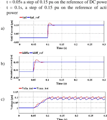
t = 0.05s a step of 0.15 pu on the reference of DC power
t = 0.1s, a step of 0.15 pu on the reference of active power
a)
b)
c)
Figure 6: Grid and differential current control simulation results
Since the DC component of the current is controlled, the power exchanged with the DC voltage source is also controlled. An unbalance between AC and DC power induces an increase or decrease of the stored energy, so an increase or decrease of the voltage vcui tot and vcli tot appears as shown on
the results in Fig 6.
3 Control of the energy
3.1 Power balance modelling
As discussed in [11], the total energy stored in an arm (Wi) is
depending on the instantaneous AC power of the phase i
p
AC i
and the power exchanged with the DC bus
p
DC i
which depends on the DC component of the differential current:
With:
Let us define:
The average value of
p
AC i is one third of the total AC power PAC which depends on the d component of the current. Thesedifferent equations may be presented as a block diagram (Fig. 7)
Figure 7: Energy model
In term of control, this block diagram highlights that the energy may be control either by the means of grid current or differential current. [12] The following sections describe the two solutions.
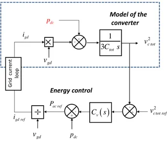
3.2 DC Power control
In this solution, the energy is supposed to be controlled by the grid current. Three independent loops have to be implemented to define the three independent references for each differential current.
As it can be sketched on Fig 8, the architecture of the control is deduced by the inversion of the model of the process. Since paci, is a disturbance, a compensation is implemented in the
control. As vdc may represent a non-linearity in case of variation of the DC bus voltage, a linearization is placed in the control.
A filter has to be inserted on the voltage measurement to avoid introducing harmonic in the generation of the reference. The power flowing through the converter is controlled by the reference on the‘d’ axis grid current.
. Figure 8: Energy control with differential current -+ 2 ci tot
v
1
totC
s
ac ip
gdi
gdv
dcv
diff ii
dc ip
1 3 -+v
c tot ref2 ++C
v
s
dcv
diff i ref P / 3 ac P -+v
ci tot2
1
totC
s
ac ip
gd i gdv
dcv
diff i p 1 3 Filter Dif fer en tial cu rr en t lo op acP
diff i ref i diff i i Model of the converter Energy control 2 2 _ _1
2
cui tot cli tot
i DC i AC i
dv
dv
dW
C
p
p
dt
N
dt
dt
(8) _.
DC i dc diff i DCp
v i
(9) 2 2 _ _ 2 _2
cui tot cli tot ci tot
v
v
The validation is performed by following simulation event:
t = 0.05s, a step of 0.05 pu on the reference of the stored energyt = 0.3s a step of 0.15 pu on the reference of active power
a)
b)
c)
d)
Figure 9: Simulation results for the energy control by the differential current
As shown in Fig 9, the total energy is under control with a response time about 100 ms. Since the energy is managed by the differential current, a step on the energy reference has a consequence on this current (Fig 9b) In other words, the energy stored in the capacitor comes from the DC voltage source. The exchange of power is managed by the reference on the grid current. Fig 9d shows the oscillations on energy in one phase which has to be filtered.
3.3 AC Power control
When the control of the energy is achieved by the grid current, it is not possible to implement three separate grid current loops since the total of the three currents is always null. This induces that only a global control of the whole energy stored in the MMC is possible. The sum of the three-phase of equations (8), leads to the following equation:
2 2 2
_ _ _
1 2
ca tot cb tot cc tot
DC AC dv dv dv C p p N dt dt dt
(11) Let us define: 2 2 2 _ _ _3
ca tot cb tot cc tot
v
v
v
(12)
The block diagram of the model is presented in the upper part of Fig 10. The lower part is describing the architecture of the control which is also deduced by the inversion of the model.
Figure 10: Energy control with grid current
The Energy control with grid current is validated by following simulation events:
t = 0.05s, a step of 0.05 pu on the reference of the stored energy
t = 0.3s a step of 0.15 pu on the reference of. DC power
a)
b)
c)
d)
Figure 11: Simulation results for the energy control by the grid current -+ 2 c tot ref v + -
v C s
gd v ac ref P dc p -+ vc tot2
1 3Ctot s gd v dc p G rid cu rr en t lo o p gd ref i gd i Model of the converter Energy controlFigure.11 shows the simulation. It can be noticed that nearly the same comments can be done as in figure 9 but the role of grid current and differential current are exchanged. Fig 11d presents the total energy stored in the converter. It can be checked that this energy is constant in steady state which confirms that there is no need to place a filter on the measurement of the energy.
4 Control of the DC voltage
As explained in the introduction, in HVDC applications it is also interesting to achieve the control of the station which is controlling the DC bus voltage. The switch in Fig. 3 is supposed to be on position 2.
4.1 Model of the system
The model of the system has to be adapted to integrate the simple model of the DC bus. The energy stored in the DC capacitor is depending on the power exchanged by the MMC (pdc) with the DC bus and the power flowing from the other
substation (ps).
The new model of the converter is presented in the middle of Fig. 12. The energy stored in the leg and the energy stored in the DC bus is clearly identified.
4.2 Description of the DC voltage control
. The same control of the energy is implemented as in section 3.3 (upper part of the figure). The control of the DC voltage is achieved by an action on the differential current.
Figure 12: Control of DC bus voltage – Model and control loops.
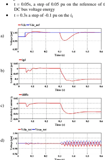
The Energy control with differential current is validated by following simulation events:
t = 0.05s, a step of 0.05 pu on the reference of the DC bus voltage energy
t = 0.3s a step of -0.1 pu on the 𝑖𝑙a)
b)
c)
d)
Figure 13 : Simulation results for the control of DC bus A step on the DC voltage reference induces a variation on the differential current. To maintain the stored energy in the arm capacitor, the regulation acts on igdref. A step on the current coming from the other station is compensated by an increase of the differential current and the grid current with a delay depending on the time response. These results show a clear decoupling of the two voltages vdc on one hand, vci tot on the
other hand.
4 Conclusion
This paper has presented the different solutions to control a MMC either connected to a voltage source or to DC bus whose voltage is varying. Two solutions of control are emerging from the definition of the energy model: control of the energy by the grid current or the differential current. Both solutions have been simulated and compared. For the DC voltage control, only one solution has been presented but both possibilities are also available. Depending on the chosen solution the exchange of power between the MMC and the AC or DC power is different. The choice done at this level may have important impact on the dynamic behavior of a
-+ vc tot ref2 + -
v C s
gd v gd ref i -+ 2 c tot v 1 3 C N s/
gd v ac p dc p 2 dc v 2 dc C s -+ l i Grid cu rr en t lo o p gd i dc p dc v s p -+ vdc ref2
vdc C s
dc v diff ref i Dif fer en tial cu rr en t lo op vdc
Model of the converter Energy control DC bus voltage control diff ref i 2 dc dc cd sdv
p
dt
C
p
(13)HVDC link or Multi Terminal DC grid. This assertion has to be studied and to be quantified.
References
[1] J.Beerten, O. Gomis-Bellmunt, X. Guillaud, J. Rimez, A. d. Meer et D. V. Hertem, «“Modeling and control of HVDC grids: a key challenge for the future power system”,» PSCC – Wroclaw 2014 – Poland.
[2] B. R. Andersen, L. Xu and K. T. G. Wong, "“Topologies for VSC transmission”," in Proc. 7th Int. Conf. AC-DC Power Transm., London, U.K.,Nov. 2001, pp. 298–304.. [3] A. Lesnicar et R. Marquardt, «”An innovative modular
multilevel converter topology suitable for a wide power range”,» in Proc. IEEE Bologna,Power Tech,Vol.3,2003. [4] S. P. Teeuwsen, «“Simplified dynamic model of a
voltage-sourced converter with modular multilevel converter design,” in Proc. IEEE Power System Conf. Expo., Seattle, WA, Mar. 2009, pp. 1–6.».
[5] J. Peralta, H. Saad, S. Dennetière, J. Mahseredjian et S. Nguefeu, «“Detailed and averaged models for a 401-level MMC-HVDC system,”IEEE Trans. Power Del., vol. 27, no. 3, pp. 1501–1508, Jul. 2012.».
[6] A. Antonopoulos et L. Angquist and H. P. Nee,, «“On dynamics and voltage control of the modular multilevel converter,” presented at the 13th Eur. Conf. Power Electron. Appl., Barcelona, Spain, Oct. 2009». [7] Z. Xu et J. Zhang, «"Circulating current suppressing
controller in modular multilevel converter", IECON 2010 - 36th Annual Conference on IEEE Industrial Electronics Society, 7-10 Nov. 2010, pp. 3198 – 3202.». [8] M. Hagiwara et H. Akagi, «“Control and Experiment of
PWM Modular Multilevel Converters”,» IEEE Transactions on Power Electronics, Vol. 24 no 7, pp. 1737-1746, July 2009..
[9] M. Hagiwara et H. Akagi, «“Control and Analysis of the Modular Multilevel Cascade Converter Based on Double-StarChopper-Cells (MMCC-DSCC)”,» , IEEE Transactions on Power Electronics, Vol. 26, no 6, pp. 1649-1658, June 2011.
[10] R.D. Middlebrook, « “Input filter considerations in design and application of switching regulators”, IEEE Industry Applications annual meeting, 1976.». [11] P. Delarue, F. Gruson et X. Guillaud, «“Energetic
Macroscopic Representation and Inversion Based Control of a Modular Multilevel Converter”,» EPE 2013 – Lille, France.
[12] H. Saad, X. Guillaud, J. Mahseredjian, S. Dennetière et S. Nguefeu, «“MMC Capacitor Voltage Decoupling and Balancing Controls”,» IEEE Transaction on Power Delivery 2014 Accepted to be published.
[13] Q. Tu, Z. Xu et L. Xu, «"Reduced Switching-Frequency Modulation and Ciculating Current Suppression for Modular Multilevel Converters",» Power Delivery,IEEE Transactions,2011.
[14] Y. Zhang, Q. Ge, R. Zhang et Y. Du, «"The control of arm currents and the parameters for modular multilevel converters",» porc.15th Int . Electrical Machines and systems(ICEMS) Conf,2012.
[15] M. Belhaouane, H. Saad et X. Guillaud, «“Control and Performance of Modular Multilevel Converters Currents using Resonant Controller”,» IECON Dallas 2014.
Index I:
System parameters: