Science Arts & Métiers (SAM)
is an open access repository that collects the work of Arts et Métiers Institute of Technology researchers and makes it freely available over the web where possible.
This is an author-deposited version published in: https://sam.ensam.eu
Handle ID: .http://hdl.handle.net/10985/19520
This document is available under CC BY license
To cite this version :
Xixi LI, ERIC MONTEIRO, Marc REBILLAT, Mikhail GUSKOV, Nazih MECHBAL
-INVESTIGATION OF NONLINEAR LAMB WAVE/DAMAGE INTERACTION: NUMERICAL AND EXPERIMENTAL APPROACHES - In: IX ECCOMAS Thematic Conference on Smart Structures and Materials, France, 2019-07 - Proceedings of the IX ECCOMAS Thematic Conference on Smart Structures and Materials - 2019
Any correspondence concerning this service should be sent to the repository Administrator : archiveouverte@ensam.eu
INVESTIGATION OF NONLINEAR LAMB WAVE/DAMAGE
INTERACTION: NUMERICAL AND EXPERIMENTAL APPROACHES
XIXI LI, ERIC MONTEIRO, MARC REBILLAT, MIKHAIL GUSKOV, NAZIH MECHBAL
Process and Engineering in Mechanics and Materials laboratory (PIMM) École nationale supérieure d'arts et métiers
151 Boulevard de l'Hôpital, 75013 Paris, France
Abstract:
One of the most important issues in engineering is the monitoring and the early detection of structural damages to prevent catastrophic failures. This process is referred to as Structural Health Monitoring and is expected to provide considerable improvements with respect to safety and maintenance costs. More particularly, the focus is here put on composite structure representative of aeronautic applications and the damages to be monitored are of “delamination” type. Nonlinear features generated by Lamb wave/damage interaction were employed for the detection of the delamination damage. Experiments are conducted on composite plates made of carbon fiber reinforced polymer equipped with two piezoelectric transducers. One plate is calibrated with a delamination damage at the center using laser shock wave technique. Nonlinear features of Lamb waves are observed in the experimental results. Finite element method is here used for investigating the nonlinear wave properties as well as the wave/damage interaction. Two damage models are studied and implemented at delamination area: a spring model and a contact model. An undamaged plate is also presented as reference in both finite element simulations and experiments. Results show that higher harmonics can be used as identification of the existence of delamination damage in a composite structure. A contact interaction model can represent the mechanical behavior of delamination damage and can be used for a real delamination modelling.Key words: Structural Health Monitoring (SHM), Lamb wave, delamination, Finite Element method
1. INTRODUCTION
One of the most important issues in engineering is the monitoring and the early detection of structural damages to prevent catastrophic failures. This process is referred to as Structural Health Monitoring (SHM) and is expected to provide considerable improvements with respect to safety and maintenance costs [1]. In SHM, the first stage and the most important part is damage detection.
In the past decades, various techniques for damage detection have been investigated. Among them the wave propagation-based method has become the most commonly used method for its
convenience and low costs. Specifically, Lamb waves are widely used in beam- and plate-like structures due to the high sensitivity to multiple defects with high precision of identification, the ability to cover entire cross-sectional area, convenience for usage, cost-effectiveness and low energy consumption [2], [3]. With a high susceptibility to interference on a propagation path, e.g. damage or a boundary, Lamb waves can travel over a long distance even in materials with a high attenuation ratio, such as carbon fiber-reinforced composites, and thus a broad area can be quickly examined [4].
So far, most of the existing Lamb wave damage detection methods are based on linear wave propagation properties, such as time of flight, reflected waves, transmitted waves and mode conversion information at the excitation frequency [5]–[8]. However, these methods are only sensitive to large defects such as an open crack, but for tiny damages nonlinear techniques are required [9]. Compared to linear techniques, nonlinear Lamb waves are more sensitive to smaller, even barely visible damages such as delaminations in composite structures or cracks. Generally, the nonlinear phenomena are induced mainly due to two types of physical mechanisms. One mechanism is related to the nonlinear relationship between strain and stress of materials in structures and components [10], [11]. The other mechanism is the so-called non-classical nonlinearity, which is often due to other mechanisms such as, for example, a contact acoustic nonlinearity (CAN) [10]. Here in this paper, a delamination type damage is focused, where nonlinearities are induced due to the second mechanism, that is, the contact between the interfaces of the delamination in composite structures.
Generally, when the incident wave passes through the damage, the damage interfaces tend to move towards each other under compressive pressure, and opposite each other under tensile pressure [10]. This may lead to the interaction between damage interfaces. In this case, when Lamb wave interacts with contact-type of damage, such as delamination damage, higher harmonics can be generated due to the contact between damage interfaces [11]–[13].
Several studies focused on the higher harmonics generated by CAN in plate-like structures. Finite element (FE) simulations and experiments were conducted to investigate the nonlinear Lamb wave/damage interaction as well as the wave propagation. Yang et al [11] carried out a three-dimensional (3D) simulation and also experiments on an aluminum plate to investigate the second harmonic generation due to a fatigue crack. The investigations were conducted using S0 and A0 Lamb waves generated by eight piezoceramic discs. Delrue et al [14] built a 3D model for a composite rectangular plate containing a circular delamination for the investigation of its nonlinear behavior. The excitation was applied by out-of-plane nodal displacement. Ramadas et al [15] the mode conversion of Lamb waves due to the presence of delamination. The delamination was modelled by de-merging the nodes at delamination region. The excitation was modelled by giving out-of-plane displacements on the surface of the composite plate. Hong
et al [16] developed a solid model for simulating the generation of the nonlinearities when
ultrasonic waves traverse a fatigued medium. The excitation was applied by piezoelectric wafers on an aluminum plate. Soleimanpour et al [12] studied the potential of a baseline-free structural health monitoring techniques based on higher harmonics resulting from the interaction of guided wave with a delamination. They employed a 3D FE model to simulate the delamination damage behavior in a composite beam, with a displacement excitation.
From the above stated studies, it can be observed that in FE simulation study, a common way to generate Lamb waves is to apply an out-of-plane displacement excitation on plate structures. This is only a simplification of the excitation by piezoelectric transducers, which are
commonly used in experiments. However, the electro-mechanical behavior of piezoelectric transducer excitations and directly displacement excitations can be quite different, and thus the wave/damage interaction may be also different from experiments. Some scholars used piezoelectric wafers to induce Lamb waves in simulation, but mostly on aluminum plates. In this study, piezoelectric elements are employed to generate Lamb waves in composite plates.
In order to test and verify the nonlinear Lamb wave/damage interaction theories and the proposed finite element models, experimental investigations are necessary, and particularly, physical supports are firstly needed. Generally, Teflon inserts [12], [17], [18], attaching industrial putties [19] and convention impacts [20][21] are the major existing techniques used for delamination generation. The main weakness with these techniques is that they do not allow for an effective control of the induced damage. For example, the calibration of delamination using impacts may induce other types of damage. As for Teflon insert technique, the problem is that it remains far from a realistic delamination damage.
As an alternative to conventional damage generation techniques, a new method named Laser Shock Wave Technique (LSWT) [22] is used to calibrate delamination damages in composites. In this paper, studies are conducted using the composite specimens with delaminations generated by laser shock. Two damage models are presented to investigate the interaction between Lamb wave and a well-controlled real delamination damage. An undamaged model is used as baseline.
This paper is organized as follows. First, the experimental configuration and results are presented in section 2. Then the FE model of a composite plate and the delamination region as well as the simulation results are illustrated in section 3. In section 3, the comparison between FE simulation and experiments are also presented. Finally, the paper is concluded in section 4. 2. EXPERIMENTAL STUDY
In this section, experiments are performed for the detection of delamination damage in composite plates.
2.1 Experimental system
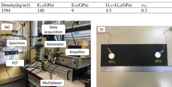
The experiments are conducted using a SHM system developed by author’s team. The experimental setup is shown in Figure 1(a). The specimen is suspended to the workbench in nearly free boundary conditions in order to prevent the specimen from interacting with other supports (e.g. test bench). Two composite plates made of carbon-fiber reinforced polymer (CFRP) are employed for testing: a damaged plate and an undamaged plate. The plates are in the size of 315×100×2.24mm3, constituting of 16 plies with a stacking sequence of [0°/90°]8.
The material properties of this plate are listed in Table 1.
Each composite plate is equipped with two PZT disks (diameter 25 mm, thickness 0.5 mm) produced by Noliac, as shown in Figure 1(b). One PZT is used as transmitter for signal generation and the other is used as signal receiver. The excitation signals are transmitted from the signal generator through the amplifier to PZT1 to generate elastic waves inside the plate. The waves propagate inside the plate and arrive at PZT2. Then PZT2 transforms the elastic waves to electrical signals, and the signals are collected by the data acquisition system. The input signal is a sine wave signal at the frequency of 109kHz with its amplitude of 10V after amplification. The sampling frequency of data acquisition is 106Hz.
The damaged plate contains a circular delamination damage at the center. Damage was introduced into samples in a calibrated way using laser shock wave technique. The specimen was subjected to a symmetrical laser impact of two laser beams. This resulted in a 7 mm diameter nearly circular delamination at midplane of the composite plate [23].
2.2 Experimental results
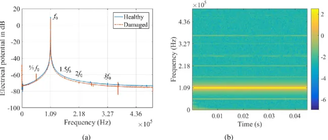
Figure 2 shows the experimental signals received by the PZT2 from both healthy and damaged plates. The results in Figure 2(a) are calculated by converting the time signal into the frequency domain using a fast Fourier transform (FFT) which includes the incident waves and the reflected waves from the plate edges and the delamination. From the signal amplitudes obtained from the undamaged plate, only one peak can be observed at 109kHz, which corresponds to the fundamental frequency. In contrast, the signal amplitudes obtained from the delaminated plate show the existence of second and third order harmonics in frequency domain. In addition, the subharmonics at 0.5 and 1.5 times of the fundamental frequency also appear. Figure 2(b) shows the short time Fourier transform of the received signal from the damaged plate. In this diagram, the subharmonics and superharmonics are also apparent. This is evidence that a delamination damage generated by laser shock induces nonlinear features of Lamb waves, and this phenomenon can be used as identification for real delamination damages in composite structures.
Table 1: Materials properties used in FE model (1 ply)
Density(kg/m3) E11(GPa) E22(GPa) G13=G12(GPa) ν12
1594 140 9 4.5 0.3
(a) (b)
Figure 2: Experimental results: (a) comparison of the responses in frequency domain for the undamaged plate
and the damaged plate. f0 is the fundamental frequency. (b) Time-frequency distribution of the experimental
signal received from the damaged plate
3. FINITE ELEMENT SIMULATION
In order to investigate the nonlinear phenomena appearing in the experiments, FE simulations are conducted. Two damage models are employed and compared, representing different interaction mechanisms between delamination interfaces.
3.1 Model of composite plate
In this section, the FE method is used to simulate the propagation of Lamb waves in a cross-ply laminated composite plate. Figure 3 shows the FE model built in the commercial software ABAQUS. In this model, the composite plate is modeled by bonding two shell layers using “tie” interaction except the delamination region. Each layer contains 8 plies. Eight-node shell elements (S8R) are used to avoid a high aspect ratio between length in the in-plane direction and thickness in through-thickness direction of the solid elements.
Two piezoelectric transducers (PZT) are bonded to the surface of the plate for transmitting and receiving electrical signals. The PZTs are modelled using quadratic solid piezoelectric elements (C3D20E). The meshes at the contact surfaces of piezoelectric elements and the plate are identical, which assures the coupling between PZT and the plate. The electrical potential of the bottom surfaces of the PZT elements are set to be 0. The input signal is exerted on the top surface of PZT1, and the electrical potential on the top surface of PZT2 is measured. A sinusoidal wave at the frequency of 109kHz is used as the excitation signal.
3.2 Element size and time step
It was shown previously [24] that in simulation of wave propagation temporal and spatial resolution should be small enough to satisfy the convergence requirements. In general, the time increment required for a dynamic analysis is
Δ𝑡 < 1 10𝑓𝑚𝑎𝑥
where Δ𝑡 is the time increment in the analysis procedure, and 𝑓𝑚𝑎𝑥 is the highest frequency of
interest. In this study, the higher harmonics in the received signals are of interest, which reflect the existence of delamination damage. Therefore, the highest frequency to be detected is the frequency of the third harmonics, i.e. 3 × 10⁹kHz = 327kHz. Then the time increment can be expressed as Δ𝑡 < 3 × 10⁻⁷s. In order to achieve better accuracy, the time step is set as 0.2μs.
In a wave propagation study, the element size is usually associated with the investigated minimum wave length 𝜆𝑚𝑖𝑛. It is generally recommended that more than 10 nodes per wave length should be used, and this criterion can be expressed as [24]
𝑙𝑒 < 𝜆𝑚𝑖𝑛 10 where 𝑙𝑒 is the element length.
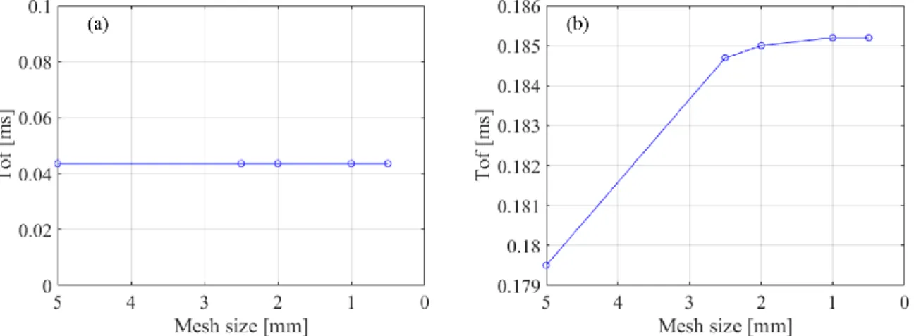
Since the number of nodes in a single wavelength can influence the accuracy of wave propagation simulation, a convergence study for element size is conducted. The model used here is the same plate model illustrated previously but with a smaller size (300mm×30mm). The excitation is a 5-circle tone-burst displacement excitation applied as a boundary condition to the left edge of the plate. Two types of excitation are considered here: the out-of-plane displacement excitation for approximation of A0 wave and the in-plane displacement excitation for approximation of S0 wave [25]. Five cases of different element sizes are studied: 5mm, 2.5mm, 2mm, 1mm and 0.5mm. The time of flight (ToF) of the amplitude is measured in the convergence study.
The effects of element sizes on ToF for both in-plane displacement excitation and out-of-plane displacement excitation are depicted in Figure 4. A straight line parallel to x-axis is shown in Figure 4(a), indicating that the ToF curve may converge at element size larger than 5mm. Thus, 5mm is accurate enough for simulating S0 wave. Meanwhile, Figure 4(b) shows a monotonic increase in ToF by decreasing the element size. The ToF first increases drastically when element size decreases from 5mm to 2.5mm, and then it shows a slight increase with element size decreasing from 2.5mm to 0.5mm. The ToF converges to 0.1803ms at element size of 1mm. However, the ToF at 2mm is 0.1801ms, showing only 0.1% difference with respect to the convergent value. Therefore, in this study, the global element size is set to be 2mm along the in-plane direction to achieve a trade-off between the simulation accuracy and computational costs. In the delamination region the local element size is set to be 0.4mm.
3.3 Damage model
In this section, two damage models are presented: the spring model and the contact model. In the spring model, delamination is modelled by adding a set of linear spring elements. These spring elements connect the nodes distributed on the delamination interfaces, as shown in Figure 5. The relative movement between delamination interfaces are controlled by the spring stiffness, which is defined along the axial direction of the spring elements, that is, the through thickness direction of the plate.
In reality, no penetration will happen between contact surfaces; however, in finite element analysis, hypothetical penetration is possible. If the spring stiffness is too small, penetration may happen between the delamination interfaces, while with a spring stiffness far too large, there won’t be any interaction between the interfaces. Therefore, an appropriate spring stiffness is needed. A sensitive analysis of spring stiffness was conducted. Several spring stiffnesses were investigated, and results show that the sensitive zone happens between 103N/m ~ 106N/m, as shown in Figure 6. Therefore, in this study, the spring stiffness is 5 × 10⁴N/m.
The contact damage model is implemented by applying a surface-to-surface contact to the delaminated region. Figure 7 shows two types of relationship between contact pressure and overclosure (interpenetration) between the surfaces: “hard” contact interaction and the free boundary condition at contact surfaces. When the contact interfaces are separated, no pressure is exerted onto the surfaces, and if contact interfaces are in contact, the penetration is 0. This avoids the hypothetical penetration in FE simulation, at the cost of longer computational time.
The delamination is a circular area located in the mid-plane of the plate, i.e. between the 8th and 9th ply. The diameter of the delamination region is 7mm. The centroid of the delamination is located at the center of the plate. An undamaged plate is also investigated for reference.
Figure 4: Effect of element size on ToF when the FE model subject to a displacement excitation at the left edge:
Figure 5: Schematic of the spring model at delamination region. The spring elements connect the nodes
distributed on the delamination interfaces. kspr is the spring stiffness.
Figure 6: Sensitivity analysis of spring stiffness in the spring damage model. 𝚫𝑼𝒛 indicates relative out-of-plane displacements between delamination interfaces. kspr is the spring stiffness.
Figure 7: Schematic of the contact pressure-overclosure relationship in the surface-to-surface contact model at
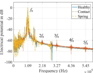
Figure 8: Simulation results: comparison of the models’ responses in frequency domain for the undamaged plate
(healthy), damaged plate model with contact interaction (contact) and damaged plate model with spring elements (spring) at delamination region. The amplitudes are normalized to the maximum amplitude of each spectrum. f0
is the fundamental frequency.
3.4 Simulation results
A comparison of the amplitudes of the received signals in frequency domain is shown in Figure 8 for the undamaged model, the spring model and contact model respectively. The signals are obtained by measuring the electrical potential at the receiving PZT and transforming into frequency domain. As shown in Figure 8, besides the fundamental frequency, the higher harmonics can be observed clearly from the contact model, including second, third, fourth and fifth order harmonics. However, in the healthy model and spring model, the peak amplitudes only appear at fundamental frequency. It can be concluded that a contact interaction model can be used to characterize the nonlinear features of Lamb wave/damage interaction, while a linear spring model is not appropriate for the representation.
3.5 Comparison between finite element simulation and experiments
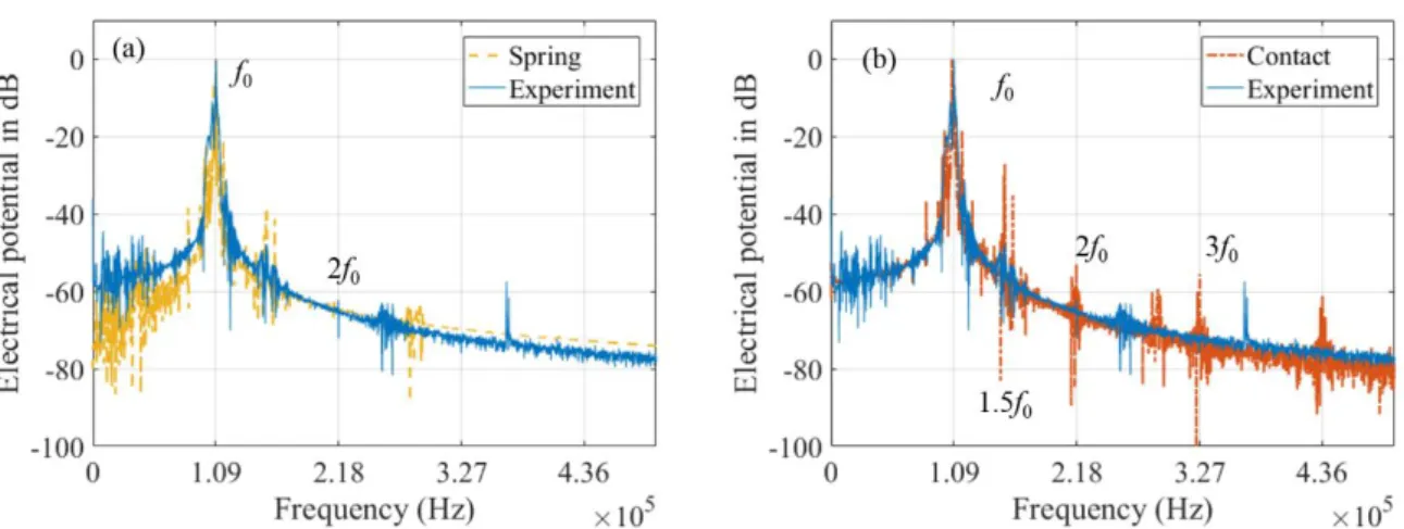
Comparisons of the amplitudes of the received signals in frequency domain from experiments and FE simulations are shown in Figure 9. The results are obtained after baseline subtraction, i.e. subtract the signals from the healthy plate. Significant difference is observed in Figure 9(a), between experimental results and FE results from the spring model. From the FE results, no super-harmonics or subharmonics can be observed in the signal amplitudes, leading to a disagreement between experiments and FE results.
In contrast, it is possible to observe from Figure 9(b) that results from contact model show good agreement with the experimental results. Both show the second and third harmonics in the amplitudes. However, in case of FE simulation data many higher harmonics are observed. On the other hand, in case of experimental data second and third harmonics as well as subharmonic at half of the fundamental frequency are distinctly alongside the other harmonics. This discrepancy between FE simulation and experimental observations may be due to the effect of the experimental system and the presence of environmental noise. From the above discussion, it can be concluded that results from the contact model shows better agreement with those from
experiments, compared to the linear spring model.
Figure 9: Comparison of amplitudes of receiving signals from experiments and FE simulations in frequency
domain after baseline subtraction: (a) experiments and linear damaged model (with linear spring elements), (b) experiments and nonlinear damaged model (with contact interaction). f0 is the fundamental frequency. 4. CONCLUSION
Nonlinear phenomena induced by delamination damage in composite structures are investigated in this paper. Experiments are conducted on a healthy plate and a plate with delamination damage generated by the laser shock technique. Fourier transform is used to transform the time signals into frequency domain. Experimental results from the damaged plate show superharmonics and subharmonics, while only fundamental frequency component appears in the healthy case. An analysis of the interaction between Lamb waves and delamination damage is performed using FE simulation method. Two damage models, the spring model and the contact model, are employed and calculated. The simulation results show that super-harmonics can be observed from the contact model, while only fundamental frequency exists in the spring model and healthy model. A comparison was conducted between experiments and FE simulations, showing that results from the contact model achieved good agreement with experimental results. In can be concluded that a contact interaction model is appropriate for characterizing the interaction between Lamb wave and a real delamination damage, and that it can be used to simulate nonlinear interaction between delamination interfaces.
REFERENCES
[1] V. Giurgiutiu, Structural health monitoring of aerospace composites. 2015.
[2] C. R. Farrar and K. Worden, “An introduction to structural health monitoring,” Philos.
Trans. R. Soc. A Math. Phys. Eng. Sci., vol. 365, no. 1851, pp. 303–315, 2007.
[3] J. L. Rose, “A Vision of Ultrasonic Guided Wave Inspection Potential,” in JProceedings
of the 7th ASME NDE Tropical Conference - 2001, 2001, pp. 1–22.
[4] Z. Su and M. Hong, “13 - Nonlinear ultrasonics for health monitoring of aerospace structures using active sparse sensor networks,” in Structural Health Monitoring (SHM)
in Aerospace Structures, F.-G. Yuan, Ed. Woodhead Publishing, 2016, pp. 353–392.
[5] P. Rajagopal and M. J. S. Lowe, “Scattering of the fundamental shear horizontal guided wave by a part-thickness crack in an isotropic plate,” J. Acoust. Soc. Am., vol. 124, no. 5, pp. 2895–2904, Nov. 2008.
[6] C. M. Yeum, H. Sohn, H. J. Lim, and J. B. Ihn, “Reference-free delamination detection using Lamb waves,” Struct. Control Heal. Monit., vol. 21, no. 5, p. n/a-n/a, Aug. 2013. [7] C. T. Ng, “On Accuracy of Analytical Modeling of Lamb Wave Scattering at
Delaminations in Multilayered Isotropic Plates,” Int. J. Struct. Stab. Dyn., vol. 15, no. 08, p. 1540010, Dec. 2015.
[8] S. Shoja, V. Berbyuk, and A. Boström, “Delamination detection in composite laminates using low frequency guided waves: Numerical simulations,” Compos. Struct., vol. 203, no. May, pp. 826–834, 2018.
[9] N. P. Yelve, M. Mitra, and P. M. Mujumdar, “Spectral damage index for estimation of breathing crack depth in an aluminum plate using nonlinear Lamb wave,” Struct. Control
Heal. Monit., vol. 21, no. 5, p. n/a-n/a, Sep. 2013.
[10] D. Broda, W. J. Staszewski, A. Martowicz, T. Uhl, and V. V. Silberschmidt, “Modelling of nonlinear crack-wave interactions for damage detection based on ultrasound - A review,” J. Sound Vib., vol. 333, no. 4, pp. 1097–1118, 2014.
[11] Y. Yang, C. T. Ng, A. Kotousov, H. Sohn, and H. J. Lim, “Second harmonic generation at fatigue cracks by low-frequency Lamb waves: Experimental and numerical studies,”
Mech. Syst. Signal Process., vol. 99, pp. 760–773, 2018.
[12] R. Soleimanpour, C.-T. Ng, and C. H. Wang, “Higher harmonic generation of guided waves at delaminations in laminated composite beams,” Struct. Heal. Monit. An Int. J., vol. 16, no. 4, pp. 400–417, 2017.
[13] S. He and C. T. Ng, “Modelling and analysis of nonlinear guided waves interaction at a breathing crack using time-domain spectral finite element method,” Smart Mater. Struct., vol. 26, no. 8, p. 85002, 2017.
[14] S. Delrue and K. Van Den Abeele, “Three-dimensional finite element simulation of closed delaminations in composite materials,” Ultrasonics, vol. 52, no. 2, pp. 315–324, 2012.
[15] C. Ramadas, K. Balasubramaniam, M. Joshi, and C. V. Krishnamurthy, “Interaction of guided Lamb waves with an asymmetrically located delamination in a laminated composite plate,” Smart Mater. Struct., vol. 19, no. 6, 2010.
[16] M. Hong, Z. Su, Q. Wang, L. Cheng, and X. Qing, “Modeling nonlinearities of ultrasonic waves for fatigue damage characterization: Theory, simulation, and experimental validation,” Ultrasonics, vol. 54, no. 3, pp. 770–778, 2014.
[17] C. A. C. Leckey, K. R. Wheeler, V. N. Hafiychuk, H. Hafiychuk, and D. A. Timuçin, “Simulation of guided-wave ultrasound propagation in composite laminates: Benchmark comparisons of numerical codes and experiment,” Ultrasonics, vol. 84, pp. 187–200, Mar. 2018.
[18] N. Quaegebeur, P. Micheau, P. Masson, and A. Maslouhi, “Structural health monitoring strategy for detection of interlaminar delamination in composite plates,” Smart Mater.
Struct., vol. 19, no. 8, p. 85005, 2010.
[19] H. Sohn, G. Park, J. R. Wait, N. P. Limback, and C. R. Farrar, “Wavelet-based active sensing for delamination detection in composite structures,” Smart Mater. Struct., vol.
13, no. 1, pp. 153–160, 2004.
[20] A. Klepka, L. Pieczonka, W. J. Staszewski, and F. Aymerich, “Impact damage detection in laminated composites by non-linear vibro-acoustic wave modulations,” Compos. Part
B Eng., vol. 65, pp. 99–108, 2014.
[21] H. Sohn et al., “Delamination detection in composites through guided wave field image processing,” Compos. Sci. Technol., vol. 71, no. 9, pp. 1250–1256, 2011.
[22] M. Ghrib et al., “Generation of controlled delaminations in composites using symmetrical laser shock configuration,” Compos. Struct., vol. 171, pp. 286–297, 2017. [23] M. Ghrib, “Structural Health Monitoring of composite structures: LASER shock
delamination generation and machine learning-based quantification,” L’École Nationale Supérieure d’Arts et Métiers, 2017.
[24] F. Moser, L. J. Jacobs, and J. Qu, “Modeling elastic wave propagation in waveguides with the finite element method,” NDT E Int., vol. 32, no. 4, pp. 225–234, Jun. 1999. [25] Y. Shen, “Structural health monitoring using linear and nonlinear ultrasonic guided
waves,” PhD Diss., p. 224, 2014.