HAL Id: hal-02472852
https://hal.archives-ouvertes.fr/hal-02472852
Submitted on 10 Feb 2020
HAL is a multi-disciplinary open access archive for the deposit and dissemination of sci-entific research documents, whether they are pub-lished or not. The documents may come from teaching and research institutions in France or abroad, or from public or private research centers.
L’archive ouverte pluridisciplinaire HAL, est destinée au dépôt et à la diffusion de documents scientifiques de niveau recherche, publiés ou non, émanant des établissements d’enseignement et de recherche français ou étrangers, des laboratoires publics ou privés.
A new scalable authentication and access control
mechanism for 5G-based IoT
Shanay Behrad, Emmanuel Bertin, Stéphane Tuffin, Noel Crespi
To cite this version:
Shanay Behrad, Emmanuel Bertin, Stéphane Tuffin, Noel Crespi. A new scalable authentication and access control mechanism for 5G-based IoT. Future Generation Computer Systems, Elsevier, 2020, 108, pp.46-61. �10.1016/j.future.2020.02.014�. �hal-02472852�
\\
A new scalable authentication and access control
mechanism for 5G-based IoT
Shanay Behrad, Emmanuel Bertin, Stéphane Tuffin, Noel Crespi
Abstract
The fifth generation of mobile networks, 5G, is expected to support a set of many requirements and use cases such as handling connectivity for a massive number of IoT (Internet of Things) devices. Authenticating IoT devices and controlling their access to the network plays a vital role in the security of these devices and of the whole cellular system. In current cellular networks, as well as in 3GPP specifications release 16 on 5G, the AAC (Authentication and Access Control) of IoT devices is done in the same manner as the AAC of MBB (Mobile Broadband) UE (User Equipment). Considering the expected growth of IoT devices, this will likely induce a very high load on the connectivity provider’s CN (Core Network) and cause network failures.
To manage the AAC of this massive number of devices, we propose an SSAAC (Slice Specific Authentication and Access Control) mechanism that makes use of the flexibility provided by virtualization technologies. This mechanism allows the authentication and access control of IoT devices to be delegated to the 3rd parties providing these devices, thereby decreasing the load of the connectivity provider’s CN, while increasing the flexibility and modularity of the whole 5G network. We evaluate the feasibility of our proposal with the OAI (Open Air Interface) open-source platform. Next, we provide a security analysis of the proposal and highlight the security requirements to use with this proposal. We also evaluate the impact of this delegation approach on the network load considering the anticipated number of AAC signaling messages compared to the existing AAC mechanisms in cellular networks. According to these evaluations, our approach is feasible and it would provide cellular networks the opportunity to overcome the security shortcomings in their AAC mechanisms. It also considerably reduces the AAC signaling load on the connectivity provider’s CN.
Keywords: AAC, IoT, 5G, Signaling load, OAI
List of acronyms
3GPP 3rd Generation Partership Project
3GW 3rd Party Provided Gateway Virtual Function
Email addresses: [email protected] (Shanay Behrad), [email protected]
(Emmanuel Bertin), [email protected] (Stéphane Tuffin), [email protected] (Noel Crespi)
AKA Autgentication and Key Agreement AAC Authentication and Access Control AF Application Function
AMF Access and Mobility Management Function
ARPF Authentication credential Repository and Processing Function AUSF Authentication Server Function
CN Core Network
EAP Extensible Authentication Protocol eNB evolved Node B
GFR Gateway Function Repository GTP GPRS Tunneling Protocol
GUMMEI Globally Unique MME Identifier
HN Home Network
IMSI International Mobile Subscriber IoT Internet of Things
MAC Medium Access Control
MANO Management and orchestration MBB Mobile Broad Band
MIMO Multiple Input Multiple Output MME Mobility Management Entity MNO Mobile Network Operator NAS Non-Access Stratum
NEF Network Exposure Function NFV Network Functions Virtualization NRF Network Repository Function
NSSAI Network Slice Selection Assistance Information NSSF Network Slice Selection Function
OAI Open Air Interface
OAI-CN Open Air Interface Core Network
OAI-RAN Open Air Interface Radio Access Network PCF Policy Control Function
PDCP Packet Data Convergence Protocol PLMN Public Land Mobile Network RAN Radio Access Network
RLC Radio Link Control RRC Radio Resource Control S1AP S1 Application Protocol
SCTP Stream Control Transmission Protocol SDR Software Defined Radio
SEAF Security Anchor Function SMF Session Management Function SN Serving Network
SSAAC Slice Specific Authentication and Access Control SUPI Subscription Permanent Identifier
TLS Transport Layer Security UDM Unified Data Management UDP User Datagram Protocol UPF User Datagram Protocol
1. Introduction
Along with mobility, security is one of the most important aspects of cellular systems. AAC (Authentication and access control) plays a vital role in ensuring the expected security level. In 3G and 4G, authentication and access control of subscribers are done through AKA (authentication and key agreement) protocols. These protocols (UMTS-AKA protocol in 3G and EPS-(UMTS-AKA in 4G) are based on the unique identities of subscribers and symmetric cryptographic algorithms [1, 2]
The system subscribers’ identities and the secret keys (that are used in symmetric cryptographic algorithms) are provisioned in secured elements (e.g., SIM cards or embedded SIM) and stored in cellular system’s database as well. Executing these AKA protocols to establish a secure connection with the cellular system is mandatory for each UE (composed of a mobile device and a secured element) to obtain its cellular connectivity [1, 2]. However, these well-established principles may prevent cellular systems from supporting the connectivity of a massive number of devices [3], in particular when considering the context of the IoT– where a high growth rate of connected devices is anticipated [4-6]. On one hand, most devices are constrained in terms of energy supply and computational capacities preventing them from running complex security protocols like EPS-AKA [7, 8, 9]. On the other hand, the tremendous number of attachment requests from these devices may induce signaling congestion by increasing the connectivity provider’s CN load [10, 11]. According to [12], the “Attach” procedure, that includes AAC, is indeed one of the most expensive procedures in terms of load on the CN. Considering this pattern, adversaries could be able to cause the denial of service attacks by generating traffic or emphasizing the natural traffic of these devices. This could result in authentication failure and connectivity loss of devices [13].
the NFV (network function virtualization) concept. These virtualization technologies offer cost-effective and flexible infrastructures to cellular systems, allowing them to provide services in a dynamic manner, by converting the physical entities of the network into virtual network functions [7]. With the concept of network slicing, virtualization technologies are also enabling customized usages of cellular systems for 3rd parties (i.e., any business actor that is not the network operator). Indeed, network slices are logical networks composed of different network functions providing specific connectivity capabilities. Each network slice can be allocated to a general requirement or use case (such as an IoT-dedicated slice) or it can be dedicated to a 3rd party to address its own specific requirements (e. g, a set of quality-of-service parameters such as throughput, latency, etc.) [14-19]. However, despite this flexibility, the architectural logic of 5G remains partly similar to that of previous physical networks: different parts of the network remain strongly coupled and dependent upon each other [20-22]. This monolithic architecture forces cellular system to have a common set of interfaces between the RAN (Radio Access Network) and the CN for all network slices, as well as to use some common network procedures. Therefore, the authentication of the devices is done before the slice selection phase (outside of the slice) and is common for all of the network slices, despite their very different specifications [23, 24]. While the 3GPP proposes some modifications (mainly for protecting user’s privacy) for authentication and access control procedures (5G-AKA, EAP-AKA’) of the devices in 5G systems (release 16) [23-25], these are still performed almost in the same manner as those of previous cellular system (EPS-AKA), along with the associated flaws for supporting a massive number of devices.
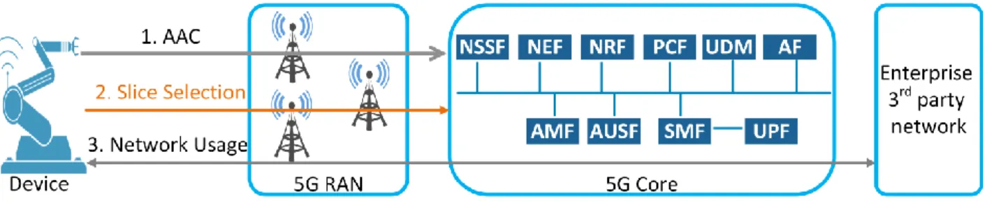
Figure 1, depicts an overview of the AAC procedure defined by 3GPP for 5G (release 16). In the first step, the device is authenticated in the network. The slice selection procedure is performed during the second step based on the first step’s result. Finally, the device gets access to the network slice in step three.
We assume that each 3rd party has subscribed to a dedicated network slice for providing services to devices from its footprint and it has a wholesale agreement with the network operator. The “3rd party network” term and the “3rd party’s slice” term have the same meaning and they are used interchangeably within the paper. The term “3rd party’s devices” refers to devices provided by the 3rd party and that should attach to the 3rd party slice. The 3rd party may produce its own devices or it may purchase them from another enterprise that will provision them with the 3rd party identities and credentials. We explain about these identities and credentials in section 2.
We propose a new approach, as an extension of the 5G-SSAAC approach we introduced in [26], to maximize the decoupling between the RAN and the CN, by delegating the AAC of IoT devices for a specific network slice to the 3rd party that uses this slice (in this case, the 3rd party is responsible to manage the identities of its devices). Thus, the AAC procedure is mainly done inside the 3rd party’s network and not outside of it. In addition to reducing the connectivity provider’s network load, our proposal addresses some other new use cases and requirements raised for 5G systems:
• Opening the network functions to 3rd parties allows verticals (such as in the industry sector) to use their pre-existing AAC infrastructure and credentials to manage the AAC of their devices in the 5G environment [27-30]. In this case, the 3rd party (e.g., an industrial actor) is able to control the lifecycle of its devices, from installation to de-installation and it does not have to obtain 5G specific credentials for its devices (i.e., user identities and cryptographic keys). In this case, if the 3rd party wants to change its wholesale agreement from one network operator to another network operator, it has not to do a mass-migration of per-device subscription information from the first operator to the second one.
• In Order to obtain business confidentiality, the 3rd party is able to shield device identities and their credentials’ privacy from the 5G network operator (the current network layout forces the 3rd parties to depend on network operators for controlling the lifecycles of their devices).
• It allows 3rd parties to choose their own AAC mechanisms according to the security requirements of their proposed services and the abilities of their devices (in terms of computational power and energy supply). This will allow the 3rd parties that provide constrained devices to manage them by using suitable ACC methods. • Finally, it gives 3rd parties the opportunity to embed connectivity in the devices they
provide to their customers, to ensure a better customer experience. In this case, the customer (i.e., the device user) does not have to set up an additional subscription and an accounting plan with a network operator, as the device provider (3rd party) has already set up a subscription for all of its devices.
The focus of the paper is not to provide a new security mechanism, but to design the Radio Access Network in a way where different security mechanisms could be provided, instead of a mandatory one as currently planned in 5G (i.e. 5G-AKA security protocol). We rely for that on the protocol flows already standardized for 5G, by introducing newly designed middle entities. In this context, the four main contributions of the paper are as follows:
• Defining new network functions in a 5G RAN to delegate the AAC of devices to the 3rd parties providing those devices.
• Assessing the feasibility of these functions and evaluating their impact on existing RAN by implementing a fully virtualized mobile network through a testbed based on the OAI (Open Air Interface) open-source product.
AKA-based AAC mechanisms.
• Describing and assessing the signaling flows that have an impact on the network signaling load by focusing on the attachment and authentication signaling.
The rest of the paper is organized as follows. In section 2 we describe the details of our proposal’s call flow and its implementation with OAI. We then provide a security analysis of our proposal and its consequences on the network in section 3. Section 4 is the performance analysis of our proposal compared to the existing AAC mechanisms for 4G and 5G cellular networks (by considering signaling load on the network). Section 5 is dedicated to the related works in the literature. Finally, our conclusion and future work are presented in section 6.
2. Authentication and access control delegation
In the current cellular networks, there is a clear border between the RAN and the CN. The main functions of the RAN are first to assign the radio resources to the UEs or devices; and second to forward signaling and data messages between devices and the CN, with all service level procedures such as AAC being performed in the CN. However, virtualization technologies make it possible to execute network functions in the best suitable location (e. g. executing CN functions in a proximity data center or RAN functions in a central data center) [31-33].
In this context, our proposal is defining a new RAN architecture that can: • Host AAC functions specific to the 3rd parties; and
• Route the AAC requests to the corresponding 3rd party network.
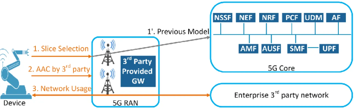
To accomplish these tasks, we introduce three new network functions for the RAN in the form of software code (three main network functions, each of them is a set of sub functions). Figure 2 depicts the general architecture of our proposal. It should be first noted that the attachment and AAC of MBB users remains unchanged in our proposal (arrow 1’), and only new 3rd party IoT devices are impacted. When a 3rd party device requires connectivity, it mentions its corresponding slice in its attachment request as the first step. The RAN processes the device’s request and routes it to the right network slice (or to the CN in case of a MBB user). In the second step, the RAN establishes a direct connection between the device and the corresponding network slice. Finally, the device is able to use the network. If the device is an MMB UE, the RAN routes the attachment request to the 5G CN and the AAC is done with the 5G AAC protocols (e.g. 5G-AKA).
2.1. Proposed network functions
The three new network functions are specified below:
• 3GW (3rd party provided GateWay virtual function): This function is under the responsibility of the 3rd party which means that the 3rd party may design this function according to its own security requirements. For example, the 3rd party may decide to design this function as a simple routing function to its slice (in this case, there is an AAC function inside the 3rd party’s network that manages the AAC of the 3rd party’s devices) or as a comprehensive AAC function. It also decides which AAC protocol to execute.
Figure 2. The general architecture of the proposed SSAAC approach
• GFR (Gateway Function Repository): This function is under the responsibility of the MNO (mobile network operator). A 3rd party first registers the code of its 3GW function through this GFR function. After this registration, the GFR keeps the information of the 3GW. The modality of this information depends on the convention between the MNO (connectivity provider) and 3rd party and on the execution infrastructure (e. g. NFV-MANO [34]).
• RCP (RRC Connection endPoint): This function is also under the MNO’s responsibility and it is the termination point of the signaling messages with the devices on the MNO’s side. In addition to the 5G RAN function, the RCP consists of three sub functions call RCP1, RCP2 and RCP3. Through these three sub functions, the gNB (next generation NodeB) is able to act according to the selected AAC protocol from the 3GW.Indeed, the RCP acts as an anchor point between the 5G network operator domain and the 3rd party domain.
With this proposal, the needed information for AAC of the devices (which are not MMB UEs) is provisioned by the 3rd party before providing the devices to the end users. This information contains the 3rd party’s Slice ID (slice identifier, corresponding to the slice subscribed by the 3rd party to the MNO) and the devices identifiers which identify each device in the 3rd party’s slice. These identifiers may differ from the globally unique identifier that is used in the current cellular systems context and in 3GPP specifications for 5G (IMSI for 4G and SUPI for 5G). The provisioned information to the devices may also contain some security credentials as well, according to the AAC mechanism that is chosen by the 3rd party. The 3rd party decides the format of the subscription identifiers, and these identifiers do not have to be 5G-specific.
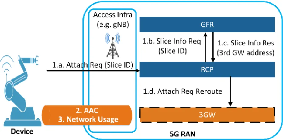
Figure 3 is a detailed view of the slice selection phase of our proposal (the first step of Fig. 2). This figure shows the execution order of the proposed network functions by the 5G RAN. We assume that the registration of the 3GW in the RAN and the storage of its address in the GFR are already completed. As the first step (the first phase of the first step in Fig. 2) the devices send their identities and the identifier of the slice (Slice ID) they want to attach, in the “Attach Req” message to the RAN (step 1.a.).Upon receiving the “Attach Req” message from the devices, the RCP function sends the slice information request message (1.b. Slice Info Req) to the GFR by mentioning the Slice ID. The GFR finds the slice information related to this Slice ID and sends this information to the RCP through the slice information response message (1.c. Slice Info Res). After receiving the
Fig 3. A detailed view of the slice selection phase in the proposed SSAAC
“Slice Info Res” message, the RCP has the needed information to establish the connection with the 3GW. Therefore, it routes the device’s attachment request to the 3GW through the “Attach Req Reroute” message (1.d. Attach Req Reroute). We provide the details of each operation in section 2.4. At the end of this stage, the slice connection is established between the device and the 3GW and the AAC can be done between the device and the 3rd party slice. For example, if the 3rd party is an automated factory with a pre-existing AAC infrastructure and database for its devices, it is able to use the mentioned slice connection for authenticating its devices and controlling their access to its network without depending on the connectivity provider.
2.2. The detailed call flow
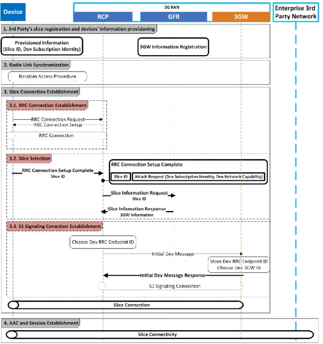
Here, we describe the detailed call flow of the proposed SSAAC procedure, from the 3rd party’s slice registration phase to the slice connectivity establishment phase. Without losing the generality of the work, we focus on the first attachment procedure of the device in the network. Figure 4, presents this call flow which contains four main phases and their associated sub-phases.
1. 3rd Party’s slice registration and devices’ information provisioning: In this phase and before starting the attachment procedure of the devices in the network, the 3rd party designs its 3GW function and registers it in a 5G network operator (MNO). The 5G network operator saves the information of this 3GW (e. g. the 3GW function’s address) in the GFR of its RAN. This registration ensures that the gNB is configured with the 3rd party slice’s information. The 3rd party also has to provision the information required to AAC of its devices’ (the Slice ID and the device’s subscription identifiers) in them.
2. Radio Link Synchronization: During this procedure, the devices get the necessary information for establishing radio connections with the gNB. The Radio Link Synchronization procedure is out of the scope of this paper (see the Random Access procedure in [35]).
Figure 4 The detailed call flow of the proposed SSAAC. The entities in bold, represent the new parts that are added to the current 4G call flow.
3. Slice Connection Establishment: This phase contains three sub-phases according to the figure 4.
3.1. RRC Connection Establishment: To establisha connection between the device and the corresponding network slice, we need to establish one connection between the device and gNB (RAN) that calls RRC Connection, and another connection between the RCP and the 3GW (the RCP acts as an interface between the 3rd party’s slices and the associated devices). The RRC Connection establishment procedure consists of two steps, the same as the RRC connection establishment procedure in LTE (i.e., 4G) [35]. The device sends an RRC Connection Request to the RAN. The 5G RAN part of the RCP gets this message and sends the RRC Connection Setup message to
the device, establishing the RRC Connection between the device and the RCP. After these two steps, the device can use the radio resources allocated through the RRC Connection Setup message.
3.2. Slice Selection: The RRC Connection Setup Complete message is sent from the device to the RAN. This message contains the Attach Request. The Attach Request consists of the device’s subscription identity and the device’s network capabilities (the device’s network capabilities’ content depends on the security requirements of the 3rd party slice. In LTE, these capabilities consist of the device’s algorithms for the 4G AAC procedures). The RRC Connection Setup Complete message also includes the slice’s ID. The device informs the RAN about the slice that it wants to connect to by using this ID (In LTE, the device sends the PLMN ID in the RRC Connection Setup message during the first attachment to the network, and in 5G, as mentioned in [35], the device sends the NSSAI in this message). Upon receiving the RRC Connection Setup message from the device, the RCP gets the 3GW information from the GFR to then forward the device’s attach request to the right slice. It obtains this information by sending the Slice Information Request message to the 3GW, specifying the Slice ID (the RCP extracts the Slice ID from the attach request embedded in the RRC Connection Setup Complete message). The GFR sends the slice information related to this Slice ID to the RCP through the Slice Information Response message. The RCP is now able to establish a connection with the 3GW Function. This connection is called an S1 Signaling Connection. If the RCP does not find its intended 3GW information from the GFR, it releases all the connections related to that device (the RRC Connection and theS1 Signaling Connection).
3.3. S1 Signaling Connection Establishment: For each device that belongs to the 3rd party’s slice, there is one S1 Signaling Connection dedicated to that device. These connections must have an identifier for each of their endpoints. Therefore, the RCP chooses an identifier for this connection on its side (the Dev RRC Endpoint ID) and sends it to the 3GW in the Initial Dev Message. The Initial Dev Message also contains the Attach request. After receiving this message, the 3GW chooses an identifier for the S1 Signaling Connection on its side (Dev 3GW’ ID) and informs the RCP about this identifier by sending the Initial Dev Message Response to the RRC Connection End Point. This completes the Slice Connection Establishment procedure and the device is connected to the 3rd party’s slice.
4. AAC and Session Establishment: All the AAC processes of the device in the network and the session establishment for providing network services to the device are done inside the corresponding 3rd party’s slice. The 3rd party organization selects which AAC mechanism to use according to its own security requirements and the security requirements of its subscribers and informs the RCP about the selected AAC mechanism (through the “Initial Dev Message Response” messaged in the previous
step). If the AAC of the device in the 3rd party’s slice is not successful, the 3GW informs the RCP by sending it an authentication failure message. Upon receiving the authentication failure message from the 3GW, the RCP releases all the connections related to that device.
2.3 Testbed
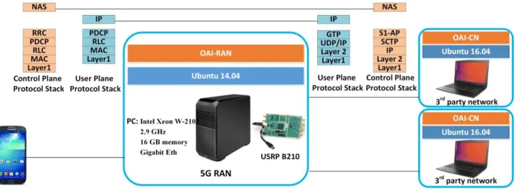
In order to evaluate the feasibility of our proposal and assess its impact on the RAN, we studied its possible implementation with OAI (Open Air Interface). OAI is open source software that implements cellular network functions of the RAN (OAI-RAN) and the core (OAI-CN). These functions are executable on general purpose processors (such as x86 and ARM). We demonstrate our proposal in this 4G environment due to unavailability of 5G devices and networks. But it will be feasible to demonstrate it in a 5G environment soon because of the fast open source developments for 5G.
Figure 5 shows a schematic view of our testbed and the protocol stacks of the control plane and the user plane. The RAN part of the proposed solution is implemented based on the OAI-RAN code. The 3rd parties’ slices (enterprise 3rd party networks) are launched based on the OAI-CN code, but it is also able to define new network functions in these slices according to the 3rd parties’ requirements. In OAI, the 4G terms are used, like eNB. But, as we target 5G, we will use the term gNB instead.
Our main purpose is focused on the RAN and on adding the proposed network functions to it. To build the radio access part (the base station), the OAI-RAN (master branch release v1.1.0) was executed on a PC with an Intel Xeon W-2102 quad-core at 2.9 GHz, 16 GB memory; USB3 and Gigabit Eth. We use a USRP B210 board for radio communications. This SDR (software defined radio) supports 2*2 MIMO (multiple-input and multiple-output) and connects to the PC through the USB3 interface. The operating system is a 64-bit Ubuntu 16.04 with a low latency kernel. To support the network slices, the OAI-CN was installed on Ubuntu 16.04 virtual machines (with kernel 4.7). We used Samsung Galaxy S4 and programmable sim cards, sysmocom for the device. We programmed them using a Gemalto IDBridge K30 as card reader/programmer hardware.
The OAI-RAN source tree consists of five main parts: Openair1, Openair2, Openair 3, Targets and Common. Openair 1 is the physical layer implementation of the RAN. Openair 2 is the implementation of the MAC, RLC, PDCP and RRC layers of the control plane and the data plane of the RAN. Openair 3 is the implementation of the UDP, GTP, SCTP, S1AP and NAS layers of the control plane and the data plane of the RAN. The hardware specific codes (drivers, tool, etc) and the main function of the OAI-RAN is in the Targets. The Common is dedicated to the common services. The OAI-RAN handles the execution of its processes though multiple threads related to different tasks (e.g. SCTP task, S1AP task, etc.). The management of these threads is done through a middleware called itti (interthread interface) and the connections between the threads are done through different types of itti messages. The different functions are designed in OAI-RAN for handling these messages such as itti_receive_msg for receiving a message from a task. As the AAC procedure is one of the control plane procedures and it is mainly related
Figure 5. Schematic view of the testbed.
to the RRC, S1AP and NAS layers, the modifications were done in the RRC, S1AP and the NAS layers of the control plane protocol stack to implement our proposal. Table 1 is a summary of the modified network functions of the OAI-RAN related to the different phases of the proposed SSAAC mechanism introduced in section 2.2. As depicted in the last row of the table, 6 OAI functions from 5 different OAI-RAN files, representing 650 lines of code are impacted, which shows the limited impact of such modifications.
2.4 Implementations
Our implementations consist of two main parts: the implementation of the GFR function and the implementation of the RCP function. In this section, first we describe the configuration of the gNB and the device. Then, we explain the detailed implementations of the proposed network functions as well as the execution of the gNB’s main function.
Table 1
The OAI-RAN files and functions that are affected by applying the proposed SSAAC mechanism. The first column “P” represents the phase number in the proposed SSAAC mechanism and the fourth column “N” represents the number of lines of code per function. The last row represents the total number of OAI-RAN files, the functions and the number of lines of code that are modified. The second phase of the proposed SSAAC mechanism (Radio Link Synchronization) does not require any changes. T means the total of previous items.
P OAI-RAN file OAI-RAN function N
1 Openair 3/S1AP/s1ap_eNB.c s1ap_eNB_register_MME 82
Openair 2/ENB_AP/enb_app.c RCconfig_S1 70
2
3 Openair3/S1AP/s1ap_eNB_nas_procedures.c
Openair3/S1AP/s1ap_eNB_handlers.c s1ap_eNB_handle_initial_context_request s1ap_eNB_handle_nas_first_req 100 150 Openair2/RRC/LITE/rrc_eNB_S1AP.c rrc_eNB_send_S1AP_NAS_FIRST_REQ 117 4 Openair2/RRC/LITE/rrc_eNB_S1AP.c rrc_eNB_process_S1AP_INITIAL_CONTEXT_SETUP_REQ 131
We launched two OAI-CNs on two systems as two network slices and considered the MME functions of these two OAI-CNs as the 3GW functions of the assumed network slices. In this assumption, the 3rd party slice carries the full features of a cellular core network but the 3rd party enterprise can customize the different network functions, including the MME network function, according to its specific requirements.
We also considered the PLMN IDs of these cores as the Slice IDs of the corresponding slices. Since we used a commercial UE with a sim card as our device, we have assumed the IMSI of the sim card as the Dev Subscription Identity of the device, but the Dev Subscription Identity can be different if another type of device is used.
2.4.1 RAN gNB and device configuration
The OAI-RAN, uses a configuration file to configure the gNB. This configuration file consists of several parameters including the parameters required to set up the physical channels, the PLMN list that stores the PLMN IDs that the gNB belongs to, the MME IP addresses the gNB can connect to and the network interface information related to the gNB. By adding several PLMN IDs (Slice Ids) and the MME IP addresses (3GW IP addresses) to the gNB configuration file, the gNB is able to connect to multiple MMEs (multiple core networks). This mechanism that enables multiple core networks to share the same RAN is called S1-flex. One of the purposes of the S1-flex technology is to provide load sharing between MMEs.
Figure 6 is a part of the configuration file that we have changed according to our setting. We have added the PLMD IDs (Slice Ids) of our two OAI-CNs (two network slices) and the MME IP addresses (3GW IP address) of these two cores to the configuration file. This configuration is the prerequisite of the phase 1 in Fig. 4 (3rd party’s slice registration and devices’ information provisioning) as we give the Slice Id of the enterprises’ slices and their addresses to the gNB. It is also possible to add a new field specific to the Slice Ids to the configuration file and to use a different format than the PLMD ID format for the Slice Id. The GFR function reads this information and registers it according to the gNB configuration file (we explain the GFR function in section 2.4.2).
For provisioning the Slice Id and the Dev Subscription Identity in the device, we have programmed two sim cards according to the PLMN IDs (Slice Ids) of the OAI-CNs (network slices). We programmed one sim card with the IMSI equal to 208920000000001 and the other one with the IMSI equal to 208930000000001. Therefore the provisioned Slice Id in the first device is 20892 and it is 20893 in the second device. The Dev Subscription Identity of both devices is 0000000001 (as they belong to different slices, they can have the same Dev Subscription Identity).
Figure.6 RAN gNB configuration. The MME has the IP address 10.193.203.33 is correlated with the mnc equals to 92 and the MME with has the IP address 10.193.202.182 is correlated with the mnc equals to
93. 2.4.2 GFR function implementation
The GFR function reads the configuration file of the gNB and verifies if the format of the Slice Id is identical to the Slice Id format of the 3rd party. In the case of using PLMN IDs instead of Slice Ids, it checks the ranges of the PLMD IDs. Function 1 is the definition of the GFR function. It gets a pointer to an itti message of the S1AP type. The structure of this message consists of the list of Slice Ids, the list of the 3GW IP addresses and the number of SCTP streams used for a 3GW (MME) association. The GFR function configures the different fields of this itti message’s structure according to the information it obtains from the gNB configuration file.
Function 1
1: function GFR(parameters: pointer to ittiMessage) 2: READ: gNB Configuration File
3: CHEACK: Slice Id Format 4: CONFIGURE: ittiMessage 5: end function
2.4.3 RCP implementation
The RCP function is the combination of three sub-functions called RCP1, RCP2 and RCP3, as well as the gNB functionalities. This function acts as an API through which the different types of AAC mechanisms can be interfaced with the OAI-RAN. The RCP’s main funtionality consists of two parts. The first part gets the Slice Id from the “RRC Connection Setup Complete” message, fetches the slice information (3GW information) from the GFR function according to this Slice Id, and sends the “Initial Dev Message” to the proper 3GW function (the 3rd phase in Fig.4). The second part receives the “Initial Dev Message Response” from the 3GW and configures the connection between the device
and the 3GW (slice) according to the information in that message. The RCP function also has to initialize the security mechanisms related to the 3rd party’s AAC method using the “Initial Dev Message Response” message.
The RCP1 function gets the “RRC Connection Setup Complete” message from the device and acts accordingly as depicted in function 2. If the device wants to connect to the network operator’s core, it provides the GUMMEI, MME code or the PLMD ID in the “RRC Connection Setup Complete” message. If it wants to connect to a 3rd party’s 3GW, it provides the Slice Id. In our setup, since we use the PLMD ID as the Slice Id, we consider a specific range for the PLMD IDs of the network operator. If the provided PLMD ID in the “RRC Connection Setup Complete” message does not belong to the network operator’s PLMN ID range, it means that the device wants to connect to a 3rd party’s network slice. The RCP1 function gets a pointer to an itti message of type S1AP and a structure of type s1ap_gNB_mme_data (described in the main function of the gNB in section 2.4.4) as the inputs. It also chooses the Dev RRC Endpoint Id for the S1 connection (sub-phase 3.3 in figure 4).
Function 2
1: function RCP1(parameters: pointer to ittiMessage, struct) 2: structure mme_desc
3: unsigned short plmn id 4: int association id
5: end structure
6: if ittiMessage->id == GUMMEI then
7: mme_desc = Select MME with GUMMEI (struct) 8: end if
9: if mme_desc == NULL then
10: if ittiMessage->id == S-TMSI then
11: mme_desc = Select MME with S-TMSI (struct) 12: end if
13: end if
14: if mme_desc == NULL then
15: mme_desc = Select MME with PLMN ID (struct) 16: end if
17: if mme_desc == NULL and ittiMessage->PLMN ID ∈ 5G core then 18: mme_desc = Select MME with Highest Capacity (struct)
19: else
20: Discard Connection 21: end if
22 SET: Dev RRC Endpoint ID 23: end function
The RCP2 function obtains the “Initial Dev Message Response” from the 3GW (MME) and creates appropriate structures for the further steps according to this message’s type. In order to have the ability to use different AAC mechanisms, we have to define different structures according to the requirements of the 3rd party’s AAC mechanism. If the message comes from the network operator’ core (e.g. 5G core), the RCP2 function creates the S1AP_INITIAL_CONTEXT_SETUP_REQ_5G_CORE structure with the security key and security algorithms fields. Then, the RCP2 sets the fields of this structure according to the keys and alorithms resulted from the AKA procedure (5G-AKA). The gNB
uses these keys and security algorithms to establish a secure connection with the device. If the “Initial Dev Message Response” message comes from a 3rd partiy’s slice, the RCP2 function creats another structure accordingly. For example, if the 3rd party would like to fully shield the devices’ identities from the operator, it has to use digital certificates and asymmetric encryption based AAC mechanism as the gNB is controlled by the network operator.
Function 3 is the definition of the RCP2 function. It waits for an itti messages of type S1AP from the 3GW (MME) and then based on to this message, it greats and configures the right type of structure.
Function 3
1: function RCP2(parameters: pointer to ittiMessage) 2: if ittiMessage->type == 5G Core then
3: structure pointer to S1AP_INITIAL_CONTEXT_SETUP_REQ_5G_CORE 4: unsigned short type
5: unsigned char key
6: unsigned short encryption_algorithm 7: unsigned short integrity_algorithm 8: end structure
9: end if
20: if ittiMessage->type == Slice x then
11: structure pointer to S1AP_INITIAL_CONTEXT_SETUP_REQ_SLICEx 12: unsigned short type
13: //define fields according to the slice x AAC mechanims 14: end structure
15: end if 16: end function
The RCP3 function is responsible for calling the appropriate security functions and securing the connection between the gNB and the device. Function 4 defines the RCP3 function showing how it gets an itti message of type RRC. The structure of this message is different depending on the required AAC mechanism. It has a fixed field calls type that clarifies the type of the AAC mechanism.
Function 4
1: function RCP3(parameters: pointer to ittiMessage) 2: switch ittiMessage->type
3: case 5G_CORE:
4: //Calls 5G Core related security functions 5 break
6: case Slice_X:
7: //Calls Slice_X related security functions 8: break
9: end switch 10: end function 2.4.4 gNB execution
The gNB functionalities of RCP operate in the main body of the gNB, therefore, we do not consider separate function names for them. Function 5 is the main function of the
program and it clarifies how to call Function 1 to Function 4. When we boot up the gNB, it makes a structure called S1AP_REGISTER_gNB_REQ that contains the 3GW IP addresses (MME IP address) and the Slice Id (PLMN ID) fields. The GFR function fills this structure according to the gNB configuration file. Considering this structure, the gNB makes SCTP associations with all the 3GWs (or MMEs) recorded in the configuration file and assigns an association Id for each of these associations. It then creates and configures a structure called s1ap_gNB_mme_data. This structure contains the PLMD ID and the association ID fields and it keeps the data of the SCTP associations.
After the device has been turned on, the gNB establishes the RRC Connection (according to the 3.1 sub-phase in figure 4) and waits for the “RRC Connection Setup Complete” message from the device. Upon receiving this message, the gNB creates a structure called S1AP_NAS_FIRST_REQ and fills the PLMD ID field of this stucture with the PLMD ID it fetches from the “RRC Connection Setup Complete” message. Then the gNB calls the RCP1 function. This function chooses the right 3GW (MME) and forwards the device attachment request to that 3GW (MME). The gNB waits for the “Initial Dev Message Response” message from the 3GW (MME). Upon receiving this message, the gNB calls the RCP2 function. Based on the type of the Initial Dev Message Response
message, the RCP2 creates and configures a proper
S1AP_INITIAL_CONTEXT_SETUP_REQ structure. Finally the gNB calls the RCP3 to
run the proper security algorithms according to the
S1AP_INITIAL_CONTEXT_SETUP_REQ structure. Function 5
1: function main
2: structure pointer to S1AP_REGISTER_gNB_REQ 3 char MME IP address[number of MMEs]
4: unsigned short plmn id[number of MMEs] 5: unsigned short SCTP streams
6: end structure
7: call GFR(arguments: pointer to S1AP_REGISTER_gNB_REQ) 8: CREAT: SCTP Association(pointer to S1AP_REGISTER_gNB_REQ) 9: structure pointer to s1ap_gNB_mme_data
10: unsigned short plmn id 11: int association id
12: end structure
13: CONFIGURE: s1ap_gNB_mme_data 14: GET RRC Connection Setup Complete
15: structure pointer to S1AP_NAS_FIRST_REQ 16: unsigned short id
17: end structure
18: S1AP_NAS_FIRST_REQ->id <- Connection Setup Complete. plmn id
19: call RCP1(arguments: pointer to S1AP_NAS_FIRST_REQ, pointer to s1ap_gNB_mme_data
20: //wait for the Initial Dev Message Response
21: call RCP2(arguments: pointer to Initial Dev Message Response)
22: call RCP3(arguments: pointer to S1AP_INITIAL_CONTEXT_SETUP_REQ) 23: end function
3. Security analysis
In this section we analyze our proposal from the security perspective. First we briefly explain the security flaws related to the AAC mechanism in 3G, 4G and 5G networks, and then we explain how our proposal can address some of these flaws. We represent the advantages of our proposal from the security point of view as well as its security concerns at the end of this section.
3.1. AKA-based AAC flaws
The architecture of 3G, 4G, and 5G networks consists of three parts: UE, SN (serving network) and HN (home network) which contains a database of the subscribers. The main AAC mechanisms used in these networks are based on the AKA protocol. The purpose of these AAC mechanisms is to establish mutual authentications between the UE and its corresponding HN and to set session keys in the UE and SN to secure the connections between them. Despite the evolutions to the AKA protocol made in each generation, the nutshell of the AAC mechanism stays the same and is based on symmetric cryptography and a secret key shared between the UE and the HN [36]. In 3G and 4G, the identity of the UE (IMSI) is sent in a clear text in the identity request part of the AKA protocol, which allows privacy attacks against the UE [37-48]. To address this problem, in 5G, the UE sends its identity protected by asymmetric encryption using the HN’s public key. Although this evolution prevents attackers from obtaining the UE’s identity, the use of asymmetric encryption is just for concealing the UE’s identity -- the AAC mechanism itself is still based on symmetric-key cryptography.
The security flaws of the AKA-based AAC mechanism used in cellular networks, the different attacks against them and their formal security analysis were studied in several pieces of research [38-43]. If we focus on 5G-AKA as the main AAC mechanism in 5G, we can see that although it is not in the operational stage yet, some security flaws have already been recognized. The vulnerabilities of the 5G-AKA and the possible attacks against it are as follows:
In 5G-AKA, first, the UE or device authenticates the network (then, the network authenticates the UE or device). For this purpose, the network (SN) sends a token to the UE (or device). If the UE can validate this token, the network authentication in the UE is successful. Otherwise, the UE sends the MAC Failure message to the network (Message Authentication Code). If the token is valid but it is not fresh (this token contains a sequence number which indicates its freshness in order to synchronize the UE and the HN and prevent the network from replay attacks [37]), the UE sends the Synchronization Failure message to the network. Both the MAC Failure message and the Synchronization Failure message are sent in clear text from the UE to the network. This vulnerability can cause the “Linkability Attack”. The attacker can capture the authentication request message which is sent from the network to the UE (or device) and replay it after. If the UE (or device) answers with the Synchronization Failure message, the attacker determines the presence of the target UE (or device) in a particular area [40-43]. In [38] the authors introduce the “Location Confidentiality Attack” which is against the user location confidentiality but as it is mentioned in [44], this attack is an extension of the “Linkability Attack”. The proposed solutions for addressing the mentioned vulnerability and the attacks
are based on the encryption of the failure messages with the public keys of the connectivity providers (operators). But in this case, there is a need for a global PKI (Public Key Infrastructure) among all the operators which is not feasible [41]. The authors in [36] also introduce another attack called “Activity Monitoring Attacks” which is also caused by the transmission of the Synchronization Failure message in clear [42]. They claimed that an attacker can break the confidentiality of the token’s sequence number (which is sent from the network to the UE) and monitor the activity of the target UE or device and learn its typical service consumption from the difference between the sequence numbers at two different times. But as it is mentioned in [44], the prerequisite of this attack is the compromise of identity confidentiality and the location confidentiality of the target UE which is difficult to obtain (especially with using the encrypted UE’s identity).
The pre-authentication messages such as the RRC (Radio Resource Control) messages (e.g., RRC Connection Request), the NAS messages (e.g., Attach Request) and some other messages (e.g., Paging) are transmitted in clear. All the following procedures between the UEs or devices and the network are based on these messages that may come from fake base stations or fake UEs [45, 46]. This vulnerability also exists in the EPS-AKA procedure in 4G and can cause the same attacks in 5G such as the DoS attacks against UEs or their location confidentiality. In 5G-AKA only the disclosure of the UE’s permanent identity which is related to this vulnerability is addressed.
The mentioned problems steam from the fact that the cellular networks are consistent with the logic of their used AAC mechanism (AKA-based AAC mechanisms with symmetric key encryption algorithms). All the required keys to secure the connection between the devices and the network are derived as the result of AKA protocols (the network design and implementation are limited to rely on only AKA-based AAC mechanisms to derive security keys). Our proposal gives the ability to the network to provide session keys for the device and the access network to secure the communications between them without relying on only an AKA-based protocol. It means that the 3rd parties can use any AAC mechanism according to their requirements and the keys for securing the connection between the devices and the network are derived according to the used AAC mechanism.
In our proposal, the security of each 3rd party network slice and its provided devices are under the responsibility of the 3rd party itself and it depends on the AAC mechanism that the 3rd party chooses to use. If the 3rd party uses an AKA-based protocol (e.g., 5G-AKA), the security level of its network slice will be the same as the security level of the current cellular networks. But as we mentioned in the paper, using our proposal, the 3rd parties can provide lightweight AAC mechanisms for their constrained devices [10] or they can also provide more secure AAC mechanisms (e.g. with asymmetric encryption) to prevent their own networks and devices from the shortcomings of the AKA-based protocols. For example, a 3rd party network slice may use longer keys in the cryptographic functions during the AAC of the devices or even it can use a post-quantum cryptography TLS in order to protect its devices and network slice against the attacks that can break the security of both symmetric asymmetric algorithms using quantum computers. As another example, a 3rd party can use Kerberos authentication protocol for its Windows devices
connecting to its company in case of remote working.
3.2. Security advantages and concerns in our proposal
One of the main network functions in the proposed 5G network architecture from 3GPP is AMF (core Access and Mobility Management Function). Not only it plays a central and vital role in the AAC mechanism, but also it acts as an interface between the devices and the other network functions because of its responsibility in the network slice selection process. Therefore, several attacks can target AMF itself and the other network functions through the AMF. Although the AMF is a virtual network function and there can be several AMFs in the network, it is a potential single point of failure. Especially with the presence of massive number of IoT devices, the AMF can be the target of intentional and unintentional DoS attacks (if a device maker wants to update the firmware of its devices at the same time which generates a lot of attach and detach messages). This DoS attack affects the AMF functionalities, the devices and the slices linked with this AMF and the other network functions such as AUSF (Authentication Server Function) that AMF sends messages to it in the AAC process. In our proposal, no network function of the connectivity provider has a central role in the attachment and the AAC of all the devices in the network. The 3GW function of each 3rd party's network slice is responsible for managing the attachment and the AAC of the devices in that slice (each 3rd party is responsible for its own devices). Therefore, the attacks such as the DoS attacks against a 3rd party’s network slice (or any network function in that slice such as its 3GW function), only affect that slice and do not compromise the whole network (the other 3rd parties’ network slices and the connectivity provider’s network and services).
The central role of the AMF in the network makes it the target of software attacks as well which causes further attacks against the other network functions (in the whole network) just like the DoS attacks. These attacks are because of sending invalid or incomplete messages to the network functions that disturb the correct behavior of the target network function or cause software crashes. In our proposal, although the RCP and the GFR network functions are shared between the 3rd parties’ network slices, the 3GW function with the central role in the AAC of the devices in the slice is a dedicated network function to the specific 3rd party’s network slice. Thus, a software attack against a 3GW function which provides a specific AAC mechanism, only affects that 3GW function and the corresponding 3rd party’s network slice (the network functions responsible for the AAC of the devices are not shared between all the devices in the network, such as the AMF function in the current 5G network architecture).
In addition to address the problems related to the AMF as the single point of failure in the current 5G architecture, our approach enables the 3rd party enterprise to conceal its provided devices’ identities and their credentials’ from the 5G network operator. It brings business confidentiality to the whole 5G system (as it is mentioned in the introduction section).
Despite all the advantages coming from the flexibility of our proposal, there are some points we have to pay attention to. Securing the isolation of the 3rd parties’ slices requires more attention. On the one hand, different slices can provide different security mechanisms according to our proposal. In this context, an attack against a slice with a
lower security level should not have an impact on the other slices [48]. On the other hand, there are common resources between the multiple slices (e.g. the spectrum; the computing resources in the gNodeB; the bandwidth on the link connecting the gNB to the 3rd party’s slice) and it is important to avoid denial of service attacks against the network slices by exposing one slice and thereby risking the exhaustion of the common resources [48]. To secure the isolation of the 3rd parties’ slices, it is important to have careful management rules and the enforcement of limits in the consumption of resources that are shared by multiple slices. If the network operator can provide secure isolation between the different slices it has wholesaled to the different 3rd parties, the misconfiguration of a 3GW function in one slice, cannot affect the other slices. In this case, well-defined security SLAs (Service Level Agreement) between the connectivity provider and the different 3rd parties, proper implementations of them and forcing all the actors to respect these SLAs, can prevent the attack and vulnerability diffusion between 3rd parties’ network slices. Of course, the mentioned attacks and vulnerabilities are related to the virtualization technologies and the infrastructure which already exists in the current 5G architecture as well.
Finally, it is important to consider that our proposal is a distributed approach (each 3rd party’s network slice owns a dedicated network function for AAC of its provided devices). Consequently, the security monitoring in this approach is more challenging than the security monitoring in a centralized approach (e.g., the AMF(s) is responsible for the AAC of the all devices in the network). In the centralized approach, the connectivity provider is the only responsible for monitoring the network functions in the AAC processes of all devices. Therefore, it can monitor the signaling traffic of the different network functions and detect the attacks (e.g., DoS attacks) against them. While in our approach the 3rd party has to monitor its own network functions and protect them from the attacks.
4. Performance analysis
In this section, we compare the performance of the AAC mechanism in 4G and 5G cellular networks with our SSAAC proposal, focusing on the signaling cost (signaling load) [3, 51]. For 4G, we consider EPS-AKA [2, 52-54] and for 5G, we consider 5G-AKA, EAP-AKA’ and EAP-TLS [12, 23, 24]. For sake of simplicity, we only consider the initial AAC for each of these mechanisms. We assume that the number of devices is n.
4.1. EPS-AKA signaling cost
According to [2], the number of CN signaling messages in the EPS-AKA procedure is 5. The CN entities involved in this procedure are the MME (Mobility Management Entity) and HSS (Home Subscriber Server). These messages are depicted in table 2. Among these messages, the “Attach request”, the “User authentication request” and the “User authentication response” are exchanged between the devices and the CN through the RAN (eNB, 4G base station). The “Attach request” message is sent through the “RRC connection setup complete” message from the device to the eNB and through the “Initial device message” from the eNB to the MME. Therefore; the “Attach request” message consists of two signaling messages on the RAN side. In this case, the number of signaling messages go through the RAN is 4 (the “User authentication request” message and the “User authentication response” message are just forwarded through the eNB). Thus, the
Table 2
The EPS-AKA procedure messages exchanged between CN entities.
Message Source Destination
1 Attach request UE MME
2 Authentication information MME HSS
3 Authentication information answer HSS MME
4 User authentication request MME UE
5 User authentication response UE MME
total signaling cost of the EPS-AKA procedure on the network for n devices is 9n (5n for CN and 4n for RAN).
4.2. 5G-AKA signaling cost
5G-AKA is used when UEs connect to the network through a 3GPP access network. According to [24], the number of CN signaling messages in the 5G-AKA procedure is 9. The CN functions involved in this procedure are the SEAF (Security Anchor Function) which is included in the AMF, the AUSF and UDM/ARPF (Unified Data Management/ Authentication Repository and Processing Function). These messages are depicted in table 3. Among these messages, the “N1 message”, the “Authentication request” message and the “Authentication response” message are exchanged between the UEs and the CN through the RAN (gNB). The “N1 message” in this procedure consists of two signaling messages on the RAN side (as with the “the “Attach request” message in the EPS-AKA procedure). Therefore, the number of signaling messages that go through the RAN is 4 and the total signaling cost of the 5G-AKA procedure on the network for n devices is 13n (9n for the CN and 4n for the RAN).
4.3. EAP-AKA’ signaling cost
The EAP-AKA’ is used when UEs connect to the network through a non-3GPP access network. According to [24], the number of CN signaling messages in the EAP-AKA’ procedure is 11. These messages are depicted in table 4. The “N1 message” (from the UE to the AMF/SEAF and from the AMF/SEAF), the “Authentication request” message and the “Authentication response” message are exchanged between the UEs and the CN through the RAN (gNB). As in the 5G-AKA, the “N1 message” which is sent from the UE Table 3
The 5G-AKA procedure messages exchanged between CN functions.
Message Source Destination
1 N1 messages UE AMF/SEAF
2 Nausf_UEAuthentication_Authenticate Request AMF/SEAF AUSF
3 Nudm_UEAuthentication_Get Request AUSF UDM/ARPF
4 Nudm_Authentication_Get Response UDM/ARPF AUSF
5 Nausf_UEAuthentication_Authenticate Response AUSF AMF/SEAF
6 Authentication Request AMF/SEAF UE
7 Authentication Response UE AMF/SEAF
8 Nausf_UEAuthentication_Authenticate Request AMF/SEAF AUSF 9 Nausf_UEAuthentication_Authenticate Response AUSF AMF/SEAF
Table 4
The EAP-AKA’ procedure messages exchanged between CN functions.
Message Source Destination
1 N1 messages UE AMF/SEAF
2 Nausf_UEAuthentication_Authenticate Request AMF/SEAF AUSF
3 Nudm_UEAuthentication_Get Request AUSF UDM/ARPF
4 Nudm_Authentication_Get Response UDM/ARPF AUSF
5 Nausf_UEAuthentication_Authenticate Response AUSF AMF/SEAF
6 Authentication Request AMF/SEAF UE
7 Authentication Response UE AMF/SEAF
8 Nausf_UEAuthentication_Authenticate Request AMF/SEAF AUSF 9 Optional exchange of further EAP messages between UE, AMF/SEAF, and AUSF 10 Nausf_UEAuthentication_Authenticate Response
(EAP success)
AUSF AMF/SEAF
11 N1 message (EAP success) AMF/SEAF UE
to the AMF/SEAF, consists of two signaling messages on the RAN side. Therefore, the number of signaling messages that go through the RAN is 5 and the total signaling cost of the EAP-AKA’ procedure on the network for n devices is 16n (11n for the CN and 5n for the RAN).
4.4 EAP-TLS signaling cost
The EAP-TLS can be used for private networks or with the IoT devices in isolated deployment scenarios (without roaming). It is an additional EAP method for primary authentication in private networks [54]. These messages are depicted in table 5. According to [24], the number of the CN’s signaling messages in the EAP-TLS procedure is 18. The messages exchanged between the UEs and the CN through the RAN (gNB) are as follows: the “Registration request”, the “Authentication Request (EAP request, EAP-TLS)”, the “Authentication Response (EAP response, EAP-EAP-TLS)”, the “Authentication Request (EAP-TLS, EAP request, TLS certificate request)”, the “Authentication Response (EAP response, TLS certificate verify)”, the “Authentication Request (EAP request, TLS finished)”, the “Authentication Response (EAP response)” and the “N1 message (EAP success)”. By considering the two parts of the “Registration request” message, the number of signaling messages that go through the RAN is 9. Therefore, the total signaling cost of the EAP-TLS procedure on the network for n devices is 27n (18n for the CN and 9n for the RAN).
4.5 SSAAC signaling cost
In our proposed SSAAC procedure, none of the signaling messages related to the IoT devices’ AAC go through the MNO’s CN. Therefore, only the RAN part of the MNO is affected by the AAC signaling cost. The numbers of messages exchanged between the devices and the RAN and between the network functions inside the RAN are 4 and they are depicted in table 6. We do not consider the messages that are related to the ACC between the devices and the 3rd party’s slice because these messages are exchanged inside the established slice connectivity (phase 4 of Fig. 4) and they do not involve the network functions which are under the responsibility of the connectivity provider (e.g.,
Table 5
The EAP-TLS procedure messages exchanged between CN functions.
Message Source Destination
1 Registration request UE AMF/SEAF
2 Nausf_UEAuthentication_Authenticate Request AMF/SEAF AUSF
3 Nudm_UEAuthentication_Get Request AUSF UDM/ARPF
4 Nudm_Authentication_Get Response UDM/ARPF AUSF
5 Nausf_UEAuthentication_Authenticate Response (EAP request, EAP-TLS)
AUSF AMF/SEAF
6 Authentication Request (EAP request, EAP-TLS) AMF/SEAF UE
7 Authentication Response (EAP response, EAP-TLS) UE AMF/SEAF 8 Nausf_UEAuthentication_Authenticate Request
(EAP response, EAP-TLS)
AMF/SEAF AUSF 9 Nausf_UEAuthentication_AuthenticateResponse
(EAP request, TLS certificate request)
AUSF AMF/SEAF
10 Authentication Request (EAP-TLS) (EAP request, TLS certificate request)
AMF/SEAF UE
11 Authentication Response (EAP response, TLS certificate verify) UE AMF/SEAF 12 Nausf_UEAuthentication_AuthenticateRequest
(EAP response, TLS certificate verify)
AMF/SEAF AUSF 13 Nausf_UEAuthentication_AuthenticateResponse (EAP request,
TLS finished)
AUSF AMF/SEAF
14 Authentication Request (EAP request, TLS finished) AMF/SEAF UE
15 Authentication Response (EAP response) UE AMF/SEAF
16 Nausf_UEAuthentication_AuthenticateRequest (EAP response) AMF/SEAF AUSF 17 Nausf_UEAuthentication_AuthenticateReSponse (EAP success) AUSF AMF/SEAFs
18 N1 message (EAP success) AMF/SEAFs UE
Table 6
The signaling messages in the proposed SSAAC procedure.
Message Source Destination
1 Attach request Device RCP
2 Slice information request RCP GFR
3 Slice information response GFR RCP
5 Attach request reroute RCP 3GW
RCP). Therefore, the total signaling cost of the proposed SSAAC procedure on the MNO’s network for n devices is 4n.
4.6 Comparison results
Table 7 gives a comparison of the different AAC mechanisms in terms of the total number of signaling messages representing the signaling cost of each protocol. We can see that the signaling costs of the AAC mechanisms used in 5G (5g-AKA, AKA’, EAP-TLS), are higher than the signaling cost of the AAC mechanism that is used in 4G (EPS-AKA). This growth in signaling cost is due to the separation between the 4G’s physical entities’ functionalities. For example, the functionalities of the MME entity in 4G have been distributed between the AMF, SMF and UDM network functions in 5G [55]. Since
Table 7
A comparison of the different AAC mechanisms’ signaling cost on the MNO’s CN, MNO’s RAN and the MNO’s whole network (CN+RAN). “n” is the number of devices.
Protocol Signaling cost on CN Signaling cost on RAN Overall signaling cost
EPS-AKA 5n 4n 9n
5G-AKA 9n 4n 13n
EAP-AKA’ 11n 5n 16n
EAP-TLS 18n 9n 27n
SSAAC 0 4n 4n
the AAC mechanisms need the signaling message exchanges between these network functions, the signaling cost becomes higher than the signaling cost in 4G. Among the AAC mechanisms for 5G, the EAP-TLS may be suitable for private networks, but it has the highest signaling cost. In our proposed SSAAC mechanism, the AAC signaling messages do not go through the MNO’s CN, and so its signaling cost on the MNO’s core network is less than that of the other procedures.
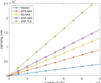
4.7 Concluding remarks
Figure 7 based on table 7 shows the comparison results of the signaling cost on the whole network (CN+RAN). From figure 7, we can see that by increasing the number of UEs (devices), the signaling costs of all of these AAC procedures increase linearly. Therefore if the network operator takes the responsibility of controlling the AAC of the massive number of devices in an IoT environment (each type with different requirements), the load of the signaling on its CN may cause network downtime and/or lead to the inability to meet QoS requirements. Even though 5G provided flexibilities qill give network operators the ability to have more than one instance of each network function and to locate them in different locations, the core network function and especially the AMFs are likely to be congested as the single point of access for the control plane [55]. By delegating the AAC of the different devices to their owners’ 3rd parties, our proposal isolates the operators’ CN from the high volume of the IoT devices’ ACC.
5 Related works
This section briefly reviews the related literature. We focus on the approaches to manage the AAC of a massive number of devices by providing group-based authentication schemas, on works that model the CN load for different purposes and on efforts to analyze the signaling performance of different AAC mechanisms.
5.1 Group-based authentication
To overcome the shortcomings of AKA protocols for constrained devices, group-based AAC mechanisms have been proposed [56]. The general process of these mechanisms is as follows:
Form a group of devices based on their local communication areas, applications or behaviors;
Choose a leader device for the group, based on its computational and battery capacities; and
Forward the signaling messages (authentication requests) of the group members to the network through this group leader [56-62].
These group-based AAC mechanisms address the requirements of constrained devices and solve the network congestion problems caused by a massive number of authentication requests. However, these group-based authentication methods have some security weaknesses. In addition to the security issues of AKA based methods used in cellular networks [63-65], group-based authentication methods encounter security problems related to their group based nature. An attacker can pose as a member of a group and get access to the network. A malicious group leader may deliberately weaken the security of the IoT devices. A security attack against this group leader could cause the leakage of the data collected from the group members or may deliver wrong commands from malicious parties to the group members [13, 66]. In our proposal, each device is authenticated separately through its corresponding 3rd party network slice. Thereby protecting the network and the devices against potential threats. Our approach also manages the requirements of each device separately and does not limit their services to the common requirements of the group.
5.2 CN load modeling
There are several proposals that address the modeling and calculating of the CN load in different manners and for different purposes.
M. M. Rahman and S. S. Heydari [65] model the number of messages generated at the MME to recover failed sessions in order to evaluate the performance of the self-healing schemes for the failed elements in the CN. J. Prados et al [67], model the control plane traffic of the CN as a G/G/m queue and then calculate the response time of the CN entities in order to resource dimensioning for providing network slice planning. In [68] the authors focus on the MME load and model it with a queuing network. They also estimate the overall system delay considering the different traffic models. A. S. Rajan et al [69] consider the MME capacity as the number of NAS messages (from the devices that want