HAL Id: hal-02491369
https://hal.telecom-paris.fr/hal-02491369
Submitted on 26 Feb 2020
HAL is a multi-disciplinary open access
archive for the deposit and dissemination of
sci-entific research documents, whether they are
pub-lished or not. The documents may come from
teaching and research institutions in France or
abroad, or from public or private research centers.
L’archive ouverte pluridisciplinaire HAL, est
destinée au dépôt et à la diffusion de documents
scientifiques de niveau recherche, publiés ou non,
émanant des établissements d’enseignement et de
recherche français ou étrangers, des laboratoires
publics ou privés.
Architecture for Future Aircraft Systems
Thibault Delmas, Luigi Iannone, Jean-Pierre Garcia, Bruno Monsuez
To cite this version:
Thibault Delmas, Luigi Iannone, Jean-Pierre Garcia, Bruno Monsuez. A New Network Configuration
Management Architecture for Future Aircraft Systems. 10th European Congress on Embedded Real
Time Software and Systems (ERTS 2020), Jan 2020, Toulouse, France. �hal-02491369�
A New Network Configuration Management
Architecture for Future Aircraft Systems
Thibault Delmas
∗, Luigi Iannone
†, Jean-Pierre Garcia
∗and Bruno Monsuez
‡∗[email protected] †[email protected], ‡[email protected]
Abstract—Aircraft systems are evolving and being enhanced thanks to new design paradigms leveraging on recent technology advances in embedded systems. However, the Integrated Modular Avionics (IMA) model, used in current avionics, has shown important limitations to accommodate such evolution. These new paradigms demand for much more global system modularity than what IMA is able to offer. Such system evolution has as well an impact on the underlying different networks present on aircrafts. In this context, it is mandatory to investigate the kind and the breadth of adaptation networks need in order to cope with new requirements.
To this end, this paper we firstly investigate the current aircrafts network configuration and management procedures. It appears that they lack the features, more specifically, the configuration management features, necessary to support these new use cases. We then look at proposals trying to fulfil this features gap. Each of them, while providing parts of the answers, also come with trade-off or insufficiencies that prevent them from fully answering to the new needs. Then, a new network configuration architecture able to cope with the newly defined configuration management requirements is provided. A comparison to the other approaches is presented, so to highlight how the proposed architecture better fulfils long-term evolution requirements while being less complex and more suitable for current configuration procedures than the other proposal. Finally, a simulation of the configuration architecture is done to provide insights on the new proposed features.
Index Terms—Network management, Real Time Management, Aircraft Systems
I. INTRODUCTION
Today aircraft systems are designed using the Integrated Modular Avionic (IMA) [1] model. In the IMA model, the configuration of such systems is created at design time. This fits in the integration model used for aircrafts, mainly because of certification and verification complexity. However, one major consequence of using such architecture is the creation of static systems, rarely evolving throughout the aircraft life cycle.
Aircrafts systems base their resilience on pure service protection through redundancy. This leads to static systems being designed offline and loaded with a monolithic behavior adjusted until it meets its safety objective. This has led to severe limitations in scalability over time due to such a static nature.
Nowadays, system engineers see new opportunities in in-novative architectures, notably, two which are of interest: the Distributed Integrated Modular Avionic (DIMA) [2]; the Flexible Platform (FP) [3]. These architectures affect the systems design and, by extension, their underlying networks,
more specifically, in how they are managed and in particular in the way devices configurations are distributed.
To better understand the challenges brought by the use of new, less rigid, architectures onto the network and what new features are necessary to cope with them, we have first to understand how the new architectures influence the systems, the networks, and their management methods and tools. As will be shown throughout the first part of this paper, an important change brought by these new architectures is the introduction of additional and alternative system modes of operation, and with it, the need, particularly for the network, to adapt to them.
In order to adapt to such changes, the whole configuration system has to be revised. To this aim, several proposals to embed part of the configuration management functions to augment the network current capabilities have been made.
We propose a network configuration architecture that, com-pared to other proposals, has low additional complexity to the current configuration tools and procedures and that pro-vides the configuration capabilities necessary for a network to become more flexible. This solution is based on a cen-tral controller, overseeing the network, capable of reacting to configuration changes while integrating in the aeronautic configuration management processes.
With this context given, the paper is organized as follows. Sec. II investigates current solutions to see how they only partially answer the requirements, formally defining the prob-lem our proposal aims at solving. Sec. III presents the current management methods and tools used in civil aeronautics. Sec. IV provides a discussion around proposals being made to cope with these new requirements. In Sec. V we introduce a new architecture that we argue to better fulfill current and future requirements. We provide an evaluation of the proposed architecture in Sec. VI, along with a first example of implementation. Sec. VII concludes the paper with a summary of new emerging requirements, a description of why it is necessary to fulfil them, and how our approach succeeds at it.
II. PROBLEMSTATEMENT
In order to better understand why configuration is critical in the context of avionics, we will first have a look at the shortcomings of the current IMA architecture. Then we will overview new emerging architectures and formalize the impact these bring to the aircraft network. This will allow us to then focus on the configuration management tools and their specific shortcomings in the next section.
A. IMA Limitations
The IMA [1] model bases its architecture around hosting multiple aircraft functions on computers on the avionic bay. These centralized functions then use the avionic network to communicate with sensors and actuator distributed aboard the aircraft. This architecture draws its fault tolerance on pure resiliency through redundancy, leading to static systems, designed offline in several refinement cycles until they meet the safety objective. One advantage of this model, ever since it was created, was its ease of mastery (for behavior provability purposes). Nevertheless, over time, it has led to severe limita-tions in scalability due to its strict static nature. Indeed, static resource reservation creates rigidity, as it limits the number of possible evolutions down the line and prevents the possibility to add different and new modes of operation. Adding new resource reservation implies to re-certify the whole system, which is a long and expensive procedure. Main example of such a restriction is the Avionics Full DupleX switched ethernet (AFDX [4]) network, which is strongly limited in the number of new admissible communications between devices. This problem is worsened by the centralized approach, with every main function being in the avionic bay, where resources may become scarce.
B. Emerging Architectures
As previously stated, there are two new emerging archi-tectures that are of interest, namely the Distributed Inte-grated Modular Avionic (DIMA) [2] and the Flexible Platform (FP) [3].
DIMA brings to light the issues that came with too much centralization and how new advances regarding embedded technologies (e.g., smart sensors) help to redistribute functions between devices in a system. This brings benefits such as reduced number of devices [5]. DIMA answers to the IMA limitations by redistributing the functions among devices and creating operational modes for those. It helps with regards to the resource utilization throughout the aircraft (bringing better balance between the avionic bay and the rest of the aircraft) and by enabling less monolithic behaviors in systems.
FP tries to extend the modularity offered by the IMA architecture in the first place. Its goal is to reach maximum modularity by providing various standardized APIs between devices to allow configuration adaptation when needed. For instance, with FP, an orchestrator is placed in one avionic bay and it is capable of migrating a function from one avionic server to another when the former suffers a failure. Differently from DIMA, FP actually leverages on the IMA model and integrates to it, but introduces a new level of flexibility, where, thanks to new APIs, functions and hardware are not anymore tight together.
As a whole, these architectures tackle the IMA rigidity by improving either the devices (in the case of DIMA) or system behavior (in the case of FP). However, it comes at the expense of monolithic operational mode, and therefore put the static resource reservation model at risk of not being able to answering new requirements that they may introduce.
Fig. 1: Aircraft system configuration management process.
One of the highlights of these new architectures from a network perspective is the need for more flexibility in system configurations. It does bring with it a new need for systems to handle more than one configuration (configuration modes for FP, and configuration extensions for DIMA).
C. Network Systems in Emerging Architectures
The need for multiple per-system configurations, described in the previous section, also impacts the underlying networks, as they also are considered systems of their own (i.e., nications systems). This opens the question whether commu-nications systems are able to handle multiple configurations. From such a perspective, the network has to provide the following three features:
• Application Programming Interfaces (APIs): FP brings
the need for APIs with the network to enable updates upon need. When the FP architecture move functions around, the network needs to be able to assure the function’s communication still get through even in its new position.
• Automation: DIMA and FP bring the need for more
automation in network configuration. Indeed, with less static communications, the handling of changes has to be automatically managed, but also kept under control.
• Adaptation: DIMA and FP are prone to create different
operational behaviors and therefore have more interaction with the network. Network has to be able to adapt to evolving operations.
Despite these new requirements, the current networks are static and can only offer solution through static configurations, as previously discussed in Sec. II-A, this severely limits or even prevents them to implement these expected features.
III. CURRENTNETWORKCONFIGURATIONMANAGEMENT
In the context of aeronautic, with the generic term configu-rationthree different entities are actually referred to, namely: configuration data, configuration software, and configuration parameters. Each one of these is tracked using part numbers. Part numbers are identifiers used to reference aircraft parts. This identifier is used to track the part and helps identify its validity for use and its place in an aircraft.
It means that from the perspective of an aircraft maintainer, a configuration file has the same life cycle as any other aircraft part. It is therefore maintained through the normal aircraft systems configuration change process, which consists of a four-step process (cf. Fig. 1).
The first step of the process is the creation of the config-uration according to strict specifications. In the second step, the configuration is validated, checking whether it is a valid system configuration. Validation is the step that is used to verify whether the created configuration is compliant with
the specification used to create it in the first place. Then, in the third step, the configuration is verified, in order to check whether it complies with the system and safety requirements (e.g., with functional testing). These two steps are performed using various tools. The fourth and final step consists in distributing the configuration to the different devices. In aero-nautic, a configuration is created, validated and verified offline at design time. An example of such creation and validation for network configurations is described in the work of Steiner et al. [6]. Distribution is done per network device thanks to the Data Loader Centralized System (DLCS) during aircraft maintenance.
When a change in the configuration occurs, it does not usually involve only one party. Airliner owning the aircraft, aircraft manufacturer making it, and device manufacturer may be involved. Each party has a role in this update process. An example of change could be the device manufacturer requiring new resources on the network (e.g., more bandwidth to another device). The update process starts with the network integrator, usually the aircraft manufacturer, turning this re-quest into specifications, then creating a new network config-uration according to these specifications. Next, a verification is performed, to ensure that there is no impact on the other devices using the network, and validating the change. Then, the integrator goes back to the device manufacturer, which will make its own internal tests to ensure the new configura-tion change fulfills its requirements. This allows to split the validation for both the integrator and the manufacturer, with the former verifying that no other system has been harmed by the change, and the latter to check whether the proposed configuration answered its initial request.
A. Configuration Management Evolution
Systems configuration, like any other system, evolves in time from two points of view: the system life cycle and the configuration update. The aircraft systems life cycle is split in several phases, or operational modes, going from its development to its end of life (cf. Fig. 2). The system starts by the development and installation phases, during which it is created, tested, and installed in the aircraft. It then enters the major part of its life cycle, looping between operation and maintenance phases. It corresponds to the commercial use of the system. Concerning configuration, its evolution requirements are traceability, validity, and integrity.
• Traceability: Any evolution (through configuration
up-date) must be traceable (through part number evolution for instance) to ensure a high degree of knowledge regard-ing the aircraft state. This is very important, as software configuration must be logged for the entire duration of the aircraft life cycle (approximatively 40 years).
• Validity: Validity from a maintenance point of view is for
a given configuration, the verification of its compatibility for use in the aircraft. Configuration part numbers helps to identify compatibility issues that could arise when installing a new configuration.
• Integrity: The configuration before installation must be
verified once distributed in the device to ensure no
Fig. 2: Aircraft system life cycle.
Fig. 3: Current configuration architecture.
tempering or degradation of the configuration happened during its installation. The current verification system is implemented with Cyclic Redundancy Check (CRC) algorithms.
The overview on how current configuration is handled gives the context in which network systems evolutions presented in Sec. II have to take place. It is important to understand how multiple configurations can exist within this context. Indeed, generating multiple configurations and switching be-tween them for different purposes has to fit with the update process up to a certain extent. Each configuration needs to be specified, created, and validated before it can be assumed safe to use. Once passed these steps, their use and integrity need to be tracked and monitored, as required by the aforementioned traceability, integrity, and validity requirements.
B. Configuration Distribution
As stated in the previous section, configuration distribution is done through the Data Loader Centralized System (DLCS). In particular, the ARINC 615A [7] file transfer protocol is used to distribute the configuration from the central DLCS to every single device. As shown in Fig. 3, the DLCS is used as a central module to send configuration individually to devices in the network, including the network devices themselves. Maintainers manually provide configuration updates to the DLCS and use a graphical interface to manually request devices to update their configuration with the newly provided one. A configuration update consists of the reboot of the device with the new configuration, followed by a safety test and a rollback in case of an invalid update.
Networks are currently considered as pre-defined closed systems, meaning that topology, load, and devices are known in advance. The implication is that any dynamic behavior, such as maintenance operations connections, as well as user-owned devices connected through onboard Wi-Fi, have already been accounted for.
Following the current situation, configuration tools in com-mercial aircrafts can be qualified as being used proactively in a distributed fashion during maintenance phase. The corollary of this qualification is that, as of today, there are no dedicated network management system aboard aircrafts. Looking at the
configuration life cycle in Fig. 1, only part of the distribution functions are embedded in the aircraft.
C. Current Tools Shortcomings
With respect to the requirements showed in the previous section, configuration distribution tools have the following shortcomings.
• APIs: The DLCS architecture offers no explicit
configu-ration API. There is an interface for human intervention only during maintenance phase, but there is no system that can connect to it to request for configuration changes.
• Automation: There is no space for automation with the
current architecture since devices get updated individually and manually and there are no APIs to do so in the first place.
• Adaptation: The current system does not implement
adaptation capabilities. Rather, if there is to be some dynamicity in an aircraft system, it has to be accounted for in the initial configuration. This is due to two factors: the limited number of possible configurations and the design philosophy of these systems.
• Traceability: There is no way for the network to
consoli-date a view of global configuration state. The traceability has to be done per device.
Regarding validity and integrity, they are currently handled respectively manually and automatically in the transfer proto-col used by the DLCS to send configurations. These, even if not limited by the current procedure, have to be kept in mind for the design of new solutions.
The main take away is that the current aircraft configuration deployment system is designed solely for human maintainers to upgrade the installed software but does not fulfil the new requirement of handling possibly sets of different configura-tions.
IV. RELATEDWORK
Few proposals exist that overcome at least partially the limitations presented in the previous sections. The first notable one is the work of Heise et al. [8] that adapts the Open-Flow [9] protocol for the aeronautical context. It offers a new network architecture, specifically designed for network (re-)configuration. This solution favors a dedicated controller that manages configurations of the network devices. It provides an API for both between the controller and the entity requesting an update and between the controller and the administered network.
OpenFlow protocol offers a good network configuration API for the data plane. Nevertheless, depending on the version, it does not address all aspects of configuration (e.g., physical layer parameters are not addressed). A great summary of the different configurations parameters for a network device is given by Aglargoz et al. [10].
For the parameters OpenFlow addresses, the controller can be used to automate the configuration distribution in the network. A real time perspective study of this behavior is provided in the original work of Heise et al. [8].
There are two shortcomings with this solution. Firstly, not embedding the controller in the aircraft means it is limited to be used only during maintenance phase. It also potentially implies the need for a specialized equipment during this phase. Secondly, configurations stay static no matter the context. It reduces its potential to adapt to systems dynamicity. However, an example of an OpenFlow protocol adaptation that allows for specific configurations to be used depending on the operating mode has been proposed by Bush et al. [11].
Gao et al. [12] propose to extend the capabilities of the existing tools and systems. Mainly by opening an API between the DLCS and remote entities (e.g., a remote maintenance operator). This conservative approach allows to provide a configuration interface for devices, while conserving as much as possible the existing established approach. However, it does offer an open API for proposals such as FP. More importantly, from a network perspective, the lack of dedicated configuration tools limits the configuration capabilities that this approach offers. Another important point is the use of the DLCS as a proxy to configure the network, meaning that no network specific functions are actually present on the DLCS. Every network management function must be either added to the devices or off-loaded to the remote entity, which makes network configuration cumbersome.
The above-described solutions are first attempts to address the requirements introduced in Sec.II-C. They adapt or add new functions to allow for better new configurations APIs and embed these functions in the network itself, so that they can be used directly on the aircraft. Nevertheless, configuration updates can still only happen during the maintenance phase of the system. This strongly limits the possible use-cases that can arise with approaches like FP. Going back to the avionic bay orchestrator example, the lack of APIs on the network limits its adaptation capabilities as well as its automation possibilities. Configuration updates in specific operational phases, such as in case of a failure, as presented in the FP proposal, open another issue. More specifically, careful evaluation of the implication of an operational phase configuration change is required as its implication on safety is not trivial. All of the proposals acknowledge the need for better configuration tools, to cope with new network requirements. The need for automatic con-figuration distribution is emphasized as it enables automation capabilities and by extension helps fulfilling the adaptation requirement.
Table I presents a summary of how the different solutions presented in this section fulfil the requirements outlined in Sec.II-C. It shows how each of the existing proposals partially answer these requirements. These solutions provide partial answers to the three requirements and each with their own trade-offs.
What can be observed is that there is a strong correlation between the capabilities offered by the APIs of the different solutions and the limitations they have. The more conserva-tive an approach is, the less it can achieve the automated configuration change envisioned, as it does not embed the necessary functions to do so. The OpenFlow approach, while very promising, remains not complete as it solely focuses on network policies.
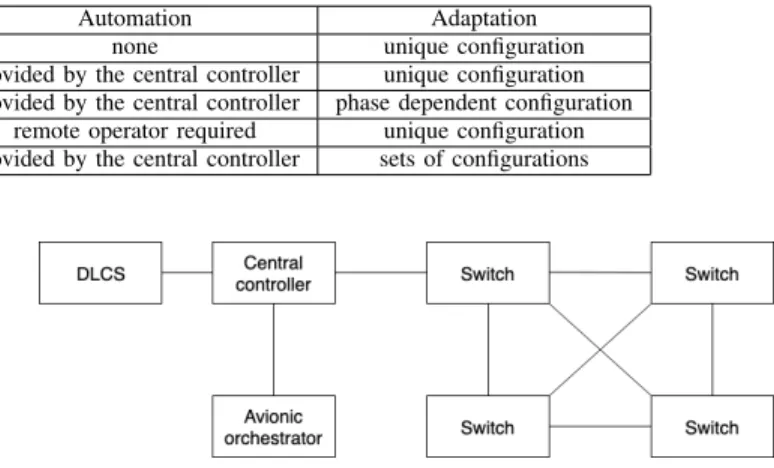
TABLE I: Configuration Management Solution vs. Requirements
Solution APIs Automation Adaptation
Current solution no API, human required none unique configuration Heise et al. [8] APIs to specific parameters provided by the central controller unique configuration Adapted OpenFlow [11] APIs to specific parameters provided by the central controller phase dependent configuration
H. Gao et al. [12] API to the DLCS remote operator required unique configuration Our proposal APIs to all parameters provided by the central controller sets of configurations
V. EVOLVEDCONFIGURATIONARCHITECTURE
The solutions presented in the previous section offer insight on the shortcomings of current configuration procedures, and how difficult it is to provide the support for systems evolution. The approach we follow embraces the new requirements, while at the same time retains the best practices from the existing solutions. To this end, we propose an architecture that provides the necessary functions for configuration distribution, while being appropriate for the current large aircraft system management.
In our approach, we embed the necessary functions to automate the distribution directly in the various steps of the management process. In this way, the possibility to validate and verify configuration thoroughly remains intact while it opens the door for switching from one pre-defined configura-tion to another.
An important aspect for the architecture definition is to address which function from the configuration procedure it should embed.
We argue that creation, validation, and verification, must stay offline since, for commercial aircrafts, they are part of a larger integration process. Aircraft system integrations are subject to strong safety and certification requirements. Precise modeling and extensive testing methods are required to answer these requirements. Moreover, their development is also subject to quality validation, depending on safety assess-ments, as defined in ARPA4754 [13]. The consequence is the necessity to provide a complete documentation and important development time to validate each configuration. It also limits the number of configurations that can be handled since each configuration must be independently qualified. It also raises the question about the admissibility of autonomous integration of additional capabilities with the need to demonstrate that the new configuration does not violate previously established and validated safety objectives.
Regarding the support of configuration transition, we first decompose these phases between mission operation, which are the phases during which the aircraft is being operated (e.g., in flight phases), and on ground-at-gate, when the aircraft is in more "relaxed" conditions. While it can be argued that in the advent of a device failure preventing a flight home for repair, transitioning between two known configurations at gate can be beneficial, it is harder to justify configuration dynamicity during flight phases.
The proposed architecture is presented in the following manner. We firstly define the components composing it and assign each their role in the configuration architecture. Then, we show how these components communicate through their dedicated network and finally we formalize the capabilities (i.e. APIs) and how each of them needs to fulfill their roles.
Fig. 4: Evolved architecture.
A. Architecture Components
There are two new components in the configuration archi-tecture that interact with two components that already exists in the current architecture (but need to be slightly modified).
In our proposal we consider that the maintenance system, i.e. the DLCS, is still there, but is now accompanied by a new component that we call the avionic orchestrator. The avionic orchestrator represents an on-board system inside the aircraft that requests the network a configuration change. Its role is to notify network devices that they have to deploy a new configuration.
The other new component of the system is the central controller. Its role is to administrate the network configurations and connect the network with the maintenance system and the avionic orchestrator. It is responsible for the network configuration deployment. The interface with the maintenance system is important to guarantee integration in the global aircraft management system, while at the same time, the interface with the avionic orchestrator offers the possibility for aircraft systems to interact with it in order to directly require configuration updates. It hosts management applications for the network which takes sets of functions to execute either when on-demand or periodically according to schedule. Such functions leverage on the knowledge the central controller has over the complete network configuration to react to APIs call from either the external entities or the network devices.
The last component we consider is the switch which is the administered device. Differently from previous components, more than one switch composes the network, however, from a logical perspective and without loss of generality, it remains just one type of component with whom to interact in the same way. It embeds a local agent responsible for its configuration management. This local agent is responsible for receiving and handling requests from the central controller.
Fig. 4 offers insight of the new network architecture we propose. With this setup, the central controller is able to receive new configurations from the maintenance system as well as change requests from the avionic orchestrator. It is able to send these configurations to the switches through the network.
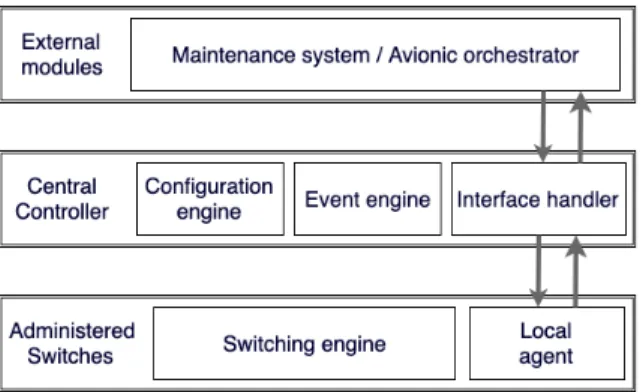
Fig. 5: Architecture components description.
Fig. 5 show each component functions. The central con-troller has three main functions. An interface handler whose role is to receive and parse the requests to and from the external entities and the network. An event engine, who triggers the necessary routines based on the incoming requests. A configuration engine that stores the current sets of available configurations.
B. Dedicated Network
Topology wise, we make use of the centralized controller, which is connected out-of-band to every device. This choice allows us to make use of a simple and dedicated configuration network, which can be based on a flooding mechanism, since this method does not require specific network configuration, hence, limiting the complexity added to the original network (e.g., no reliance on DHCP [14] or ARP [15] protocols). Such an approach is possible thanks to one of the benefits of controlled environments, such as an aircraft, where it is possible to know in advance the MAC addresses of each device in the network. For instance, AFDX switches use Ethernet MAC addresses that are based on their position in the aircraft, configured via hardware pins. We can safely make a similar assumption, where the controller is aware of the MAC address of each device that may interact with it.
The dedicated network is therefore configured to flood every message from the controller to the switches. Flooding in this case is used so that every switch receives every communication from the network. Special care is necessary in the implementation of the flooding mechanism in order to not overburden the network with traffic and to not generate loops which would result in packet storms. This is made possible thanks to the regular nature of the network topology, a ladder mesh network, which is very similar to the one currently used in aircrafts [16]. It requires the central controller position known in the topology and systematic use of ports.
The flooding mechanism illustrated in Fig. 6 is done in the following patterns. Every message that enters the port linking the switch to the previous one is in the topology is forwarded. The topology is divided into two sides, the right one and the left one. The switch on the right side forwards the message to the next right and left switches and the same-level left switch. Similarly, the left switch forwards the message the next right and the next left switches and the same-level right switch. This
Fig. 6: Evolved architecture massages flooding.
pattern covers the entire topology and can be used recursively as the ladder mesh expands. Moreover, the opposite direction flooding, from switches to the controller, is done from the switch local agent towards the beginning of the topology where the central controller is located. This approach ensuring that every flow is moving only one way in the ladder enables to prevent the creation of loops in the network.
We propose to use a flooding-based approach in order to keep the architecture very simple. Nevertheless, flooding is known to be bandwidth inefficient, and as such, it is important to estimate how much bandwidth is actually needed. To this end, we perform an analytical estimation of the bandwidth consumed at each switch, based on a simple topology in Sec. VI.
C. APIs
The configuration architecture has two types of interfaces. The ones with the maintenance system and avionic orchestra-tor and the one between the central controller and the switches. The first type is defined to provide access to the network configuration capabilities to these external components.
The central controller/external entities APIs are:
Node Configuration: This primitive returns to the external entity the current configuration of the network. It is essen-tial for network state reporting and aircraft configuration validation.
Node Configuration Update: This primitive triggers a con-figuration change on the network based on the request intent (e.g., change one or multiple configurations). Node Monitoring Management: This primitive triggers a
monitoring configuration on one of the switches. It is used for maintenance troubleshooting.
Node Event Reporting: This primitive provides a subscrip-tion channel to offer publishing capabilities to commu-nicate their current state to the central controller in an on-demand fashion. Its main use is for external entities to be able to adopt specific behaviors with the central controller.
The second type is defined to enable the central controller to manage the network. These APIs are:
Get: Primitive to get the current configuration of a device. Necessary for safety tests of the network.
Set: Primitive to send a new configuration. Necessary to update configuration parameters. Setting it as an abstract
primitive allows to specify a flexible wire format that either sends a whole new configuration or solely a specific parameter change.
Report: Reporting device capabilities for multi-vendor net-work for example. It serves fewer purposes in integrated networks, nevertheless, it can be useful for an on-line system check.
Subscribe: Subscribing to specific events and state teleme-try is an important management capability for dynamic management. Considering the requirements, it may have a limited use, since telemetry policy will be designed offline, however, it can enable specific on-line tests on demand.
The API can be implemented as UDP streams, since such a solution offers the lightest implementation to transfer files. Compared to the currently used ARINC615A protocol, the main point that needs to be implemented is the verification handshake to accept the new file (through version checking) and the integrity check upon reception (i.e., the Cyclic Redun-dancy Code -CRC- recalculation).
The above API is generic enough, so to adapt to the differ-ent granularity of the various network devices configuration parameters. Routines leveraging on this API can also be implemented to accommodate testing or network validation during development phases. For instance, extensive link status monitoring can be required through the monitoring primitives (report/subscribe) for on field-testing. This architecture retains compliance with the DLCS management model and allows the creation of a dedicated overlay that supports the evolution and requirements of future systems as presented before.
D. Configuration Routine Example
Our approach allows to implement the controller side and the device side completely independent, which helps to intro-duce modularity in the network. If a new switch is installed, for example to replace a broken one, the network can push the intended configuration it requires based on its place in the topology. In order to do so, the central controller uses the Get primitive to request for switch configurations, receives an empty or invalid one from the newly placed switch which triggers it to push the intended one to said switch, allowing for its use in the aircraft. This kind of routine is of use during maintenance phases to ease the installation process of a replacement device.
The proposed architecture achieves the objectives outlined in Sec.II, introducing a well-defined API allowing flexible configuration deployment while retaining simplicity and the philosophy of the current system. Sec. VI will show how it is in line with aircrafts’ requirements.
VI. EVALUATION
We evaluate our proposed architecture in two different ways. First, we summarize the tradeoffs made by our architecture and the ones described in Sec. IV with respect to maintenance and new use-cases requirements. Then, a first implementation of the architecture through simulation is proposed and proof of concept for the network configuration service is implemented using mininet [17] and the gRPC [18] framework.
A. Tradeoff Summary
As explained in Sec. IV, proposals are being created around the OpenFlow protocol. Comparing the OpenFlow based solution to ours revolves around studying two aspects of the proposed solutions: capabilities and maintenance require-ments. Capability wise, both solutions try to offer a way to automate configuration distribution with one key difference: the use of the OpenFlow protocol limits the engineers to the configurations of switch rules. Furthermore, when OpenFlow is used to configure networks, it is used in coordination with complementary protocols for other parameters which are not directly network related. This limits what their solution is able to configure. Whereas by sticking to file-based management, we ensure that the configuration protocol is not bound to any specific aspects of network configuration. The proposed architecture does not modify current configuration manage-ment process, as opposed to OpenFlow based solutions. An important aspect of configuration validation in aircrafts is the fact that the final configuration is always verified. Whereas OpenFlow based solution relies on the conversion of Open-Flow messages into a final configuration. The closer the configuration is to hardware, like in our proposal, the less conversion steps are needed, and therefore the less possible unintended interpretation of the configuration arise.
Concerning the maintenance qualities, it is quite hard to evaluate for Consumer-Off-The-Shelf (COTS) protocols, as they do not follow development processes that are compatible with the expected constraints and safety of airworthy technolo-gies. This leads to the use of technologies such as TCP for sessions between the controller and their administered devices. Another important difference can be found in the traceability aspect of the configuration update process. In general, con-figuration of aircraft systems is done by means of files and not by individual parameters. This is done to ease and ensure traceability of any change in aircrafts system configuration. Even though per-flow management, like in OpenFlow, has shown numerous advantages for network administrators, it may reveal to be incompatible with aircrafts configuration update process. Indeed, a per-flow approach may dilute the modified information in several pieces, in contrast of the ne-cessity to keep it unfragmented in order to guarantee consistent traceability of the systems evolution. Validity and integrity are also harder to evaluate for a parameter-based configuration protocol as the final configuration is created by the device based on the requests it receives. There is no direct mechanism to ensure that the configuration request sent is correct from a validity or integrity standpoint.
Table I, in Sec. IV, already shows the main benefits of our architecture benefits. The comparison between the proposed management architecture or the solution proposed Gao et al. [12], is mainly based on available capabilities. The use of RPCs that re-implement existing functions allow keeping already existing procedures. This implies that current con-figuration tools/procedures, from an aircraft perspective, can still be reused while the network can explore new operational services.
Fig. 7: Flooding in ladder meshed topology.
B. Analytical Evaluation of Network Bandwidth
The topology following a mesh ladder pattern, having N rows and 2 sides, namely, Right and Le f t, as presented in Fig. 7. The streams from the central controller are flooded to the end of the topology following the pattern, represented as well in Fig. 7 and described in Sec. V-B.
A switch Rn, on the Right side of the ladder, receiving a
stream s will send such a stream to: the next Right side switch Rn+1; the next Le f t switch Ln+1; the Le f t switch on the same row Ln. Symmetrically, a stream arriving on the current Le f t
side switch Ln will re-emit it to: Ln+1; Rn+1; Rn.
Therefore, a switch Ln+1 receives four copies of a stream; one from Rn itself, two through Ln and one through Rn+1.
Same for Rn+1 that receives four copies of a stream; one from Rn itself, two through Ln, and one through Ln+1.
This enable to draw this recurring relation to calculate the number of times N BS(n) a stream is received at a given node:
N BS(n)= 4 ∗ NBS(n − 2) ∀n > 2
with N BS(1)= NBS(2)= 1. The bandwidth used by streams
at a given switch therefore can be calculated by dividing the link capacity (in the test network 1gb/s) by the number of replicated streams the network N BS(n). Such bandwidth can
be used to calculate the theoretical transfer time of a file of size S as a reference for the simulation results.
C. Simulations
We started by simulating our architecture so to offer a first representation of how the management architecture works, before going to a more adequate production-ready implemen-tation. This evaluation looks at the timeliness of the distri-bution mechanism with our proposal. The gRPC framework allows to implement the API defined in Sec V as Remote Procedure Calls (RPCs) [19]. Mininet is used as a network simulation environment, since it allows to deploy the topology and emulate the architecture.
The simulation implements a sequential installation of con-figuration files to each switch in the network. Each switch runs an RPC server ready to receive the file and its metadata, while the controller acts as the RPC client using gRPC streams
Fig. 8: Per-node file transfer time.
to send them. The network is statically configured so that the streams are flooded across the network as previously described.
D. Results
Fig. 8 shows the measured time for each node to receive 1, 10, and 100 megabytes files. Nodes with lower number are closer to the controller. The closest the switches are to the controller, the lower the transfer time. This can be explained by the feedback effect of flooding. Indeed, network load increases as the distance between the controller and the node does as flooding generate more traffic the longer the network is. This phenomenon is well known and is also called broadcast storm. Thus, lowering the effective bandwidth at the end of the network. To limit such excessive bandwidth consumption, we limited the packets Time To Live (TTL) in the network, so to decrease the number of unwanted replicas. An unwanted replica is one that goes along a network beyond its destination. Another option would be to change the controller placement to mitigate this performance drop, but its position on the network topology is selected to match the reality of an aircraft structure. Usually, aircraft computers sit at the front of the aircraft for hardware accessibility and less environment requirements.
The performance is also limited by two other factors. One is the fact that simulations are performed on top of a virtual machine on an Apple laptop, using 2 VCPUs and 4GB of RAM. The second factor is the use of TCP by gRPC. TCP reacts poorly to the duplicates generated by the flooding mech-anism, because it considers duplicates as a sign of congestion, so triggering its congestion control mechanism, which keeps throughput low.
Cumulated transfer times from Fig. 8, while realistically slow, averaging at around thirty minutes for the 100MB files scenario, still shows promising results as the typical accepted time for a configuration change by airliners is fifteen minutes. However, typical configurations are way smaller than that in embedded contexts. More importantly, it shows that despite severe bandwidth limitations in a representative network, the architecture simplicity shows advantages in system flexibility such as not requiring the use of complex network discovery mechanisms.
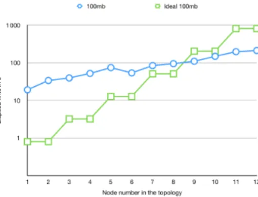
Fig. 9: Ideal vs Simulated transfer time.
As expected, the configuration deployment time scales with the file sizes and the available bandwidth. File size linearly increases the transfer time while controller/switch distance in the topology increases it exponentially as shown by the linear curve in the logarithmic scale. This can be observed particularly well by the ideal curve in Fig. 9.
Fig. 9, already discussed in Sec. VI-B, also shows the measured transfer time for each node. At first, on near nodes, completion time is very far from ideal which can be explained by the simulation limitations. Once bandwidth becomes less available as the flooding mechanism creates more replicas, the ideal time becomes less viable. Our solution performs well, close to ideal, because of the TTL limitation that we introduced in our simulations, showing the effectiveness of such mechanism.
As a proof of concept, this simulation highlights the strength of our configuration architecture. Indeed, the defined API has powerful primitives to create configuration routines according to either maintenance needs or system behaviors. Moreover, despite the aggressive flooding mechanism made to avoid the introduction of complexity in the network, the performance seems tolerable from a maintenance perspective.
VII. CONCLUSION
The new architectures for aircraft systems impose new requirements to embedded networks. Throughout this paper, we presented the new evolutions happening from a system-engineering point of view and how these will affect underlying networks. Aircraft networks will need to cope with more modular systems than before. Nevertheless, at present, these networks have static behaviors and cannot cope with these changes due to a lack of configuration management capabili-ties.
We investigated the current configuration procedures aboard aircrafts to better understand their limitations. We argued that two kind of requirements arise for a new configuration architecture. The first kind being related to the newly expected network capabilities and the second one being related the maintenance procedures expectation.
We looked at proposals being made to enhance the current solutions. Current proposals lack either sufficient capabilities to cope with the needed network adaptiveness or do not answer
the requirements fully as they focus on specific aspects of network configuration.
We propose a new configuration architecture that supports the emerging use-cases while answering these requirements. Our solution leverages various advances in network man-agement design, while proposing a modular architecture that integrates in aeronautical procedures. Both from a system integration point of view and from a network configuration one.
We evaluated a proof of concept based on our configuration architecture to investigate its capabilities and performance. We found that our robust architecture, while refraining from adding too much complexity to the network, still enables to implement the capabilities we were looking for, while respecting the two kind of requirements we aimed to fulfil.
Early results for a simple network configuration architecture are promising, and suggest that the proposed solution will help to support long-term evolutions of aircraft systems.
REFERENCES
[1] C. B. Watkins and R. Walter, “Transitioning from federated avionics architectures to integrated modular avionics,” in Digital Avionics Systems Conference, 2007. DASC’07. IEEE/AIAA 26th. IEEE, 2007. [2] Y. Hao, X. Zhang, X. Cui, and B. Huang, “Design and realization of
ima/dima system management based on avionics switched network,” in 2016 International Conference on Computer, Information and Telecom-munication Systems (CITS). Kunming, China: IEEE, 2016.
[3] S. Korn, R.-R. Riebeling, S. Görke, and R. Reichel, “Flexible platform approach for cs27/29 fly-by-wire systems,” 2013.
[4] A. R. incorporated. Arinc 664 p 7 Avionics full duplex networks. [Online]. Available: https://standards.globalspec.com/std/1283307/arinc-664-p7
[5] M. S. Haouati, “Architectures innovantes de systèmes de commandes de vol,” Ph.D. dissertation, Institut National Polytechnique de Toulouse-INPT, 2010.
[6] W. Steiner, M. Gutiérrez, Z. Matyas, F. Pozo, and G. Rodriguez-Navas, “Current techniques, trends, and new horizons in avionics networks configuration,” in 2015 IEEE/AIAA 34th Digital Avionics Systems Con-ference (DASC). San Diego, California, USA: IEEE, 2015.
[7] A. R. incorporated. Arinc 615a software data loader using ethernet interface. [Online]. Available: https://standards.globalspec.com/std/1017557/arinc-615a
[8] P. Heise, F. Geyer, and R. Obermaisser, “Self-configuring deterministic network with in-band configuration channel,” in Software Defined Sys-tems (SDS), 2017 Fourth International Conference on. Valencia, Spain: IEEE, 2017.
[9] N. McKeown, T. Anderson, H. Balakrishnan, G. Parulkar, L. Peterson, J. Rexford, S. Shenker, and J. Turner, “Openflow: enabling innovation in campus networks,” ACM SIGCOMM Computer Communication Review, vol. 38, no. 2, 2008.
[10] A. Aglargoz, A. Bierig, and A. Reinhardt, “Dynamic reconfigurability of wireless sensor and actuator networks in aircraft,” in 2017 IEEE Inter-national Conference on Wireless for Space and Extreme Environments (WiSEE). IEEE, 2017, pp. 1–6.
[11] J. E. Bush, A. Ayyagari, and S. L. Arnold, “System and method for automatic generation of filter rules,” Oct. 5 2017, uS Patent App. 15/088,006.
[12] H. Gao, A. Jasti, and R. Pendse, “An intelligent network monitoring and management tool for aircraft data networks,” in 24th Digital Avionics Systems Conference, vol. 2. IEEE, 2005, pp. 7–pp.
[13] S. ARP4754, “Certification considerations for highly-integrated or com-plex aircraft systems,” SAE, Warrendale, PA, 1996.
[14] R. Droms, “Rfc 2131-dynamic host configuration protocol, march 1997,” Obsoletes RFC1541. Status: DRAFT STANDARD, vol. 3, no. 1, 1997. [15] D. C. Plummer, “Rfc 826: An ethernet address resolution protocol,”
InterNet Network Working Group, 1982.
[16] B. Annighoefer, C. Reif, and F. Thieleck, “Network topology optimiza-tion for distributed integrated modular avionics,” in 2014 IEEE/AIAA 33rd Digital Avionics Systems Conference (DASC). IEEE, 2014, pp. 4A1–1.
[17] B. Lantz, B. Heller, and N. McKeown, “A network in a laptop: rapid prototyping for software-defined networks,” in Proceedings of the 9th ACM SIGCOMM Workshop on Hot Topics in Networks. ACM, 2010. [18] Google. (2017) grpc network management interface. [Online]. Available:
https://github.com/openconfig/gnmi
[19] A. D. Birrell and B. J. Nelson, “Implementing remote procedure calls,” ACM Transactions on Computer Systems (TOCS), vol. 2, no. 1, pp. 39– 59, 1984.