HAL Id: hal-02285013
https://hal.archives-ouvertes.fr/hal-02285013
Submitted on 12 Sep 2019
HAL is a multi-disciplinary open access
archive for the deposit and dissemination of
sci-entific research documents, whether they are
pub-lished or not. The documents may come from
teaching and research institutions in France or
abroad, or from public or private research centers.
L’archive ouverte pluridisciplinaire HAL, est
destinée au dépôt et à la diffusion de documents
scientifiques de niveau recherche, publiés ou non,
émanant des établissements d’enseignement et de
recherche français ou étrangers, des laboratoires
publics ou privés.
An Integrated Model-based Tool Chain for Managing
Variability in Complex System Design
Damir Bilic, Etienne Brosse, Andrey Sadovykh, Dragos Truscan, Hugo
Bruneliere, Uwe Ryssel
To cite this version:
Damir Bilic, Etienne Brosse, Andrey Sadovykh, Dragos Truscan, Hugo Bruneliere, et al.. An
Inte-grated Model-based Tool Chain for Managing Variability in Complex System Design. Models and
Evolution Workshop (ME 2019), co-located with the IEEE / ACM 22nd International Conference on
Model Driven Engineering Languages and Systems (MODELS 2019), Sep 2019, Munich, Germany.
�10.1109/MODELS-C.2019.00045�. �hal-02285013�
An Integrated Model-based Tool Chain for
Managing Variability in Complex System Design
Damir Bilic
M¨alardalen University V¨aster˚as, Sweden [email protected]Etienne Brosse
Softeam Paris, France [email protected]Andrey Sadovykh
Softeam, Paris, France
Innopolis University, Innopolis, Russia [email protected], [email protected]
Dragos Truscan
˚
Abo Akademi University Turku, Finland [email protected]
Hugo Bruneliere
IMT Atlantique, LS2N (CNRS), ARMINES Nantes, France [email protected]
Uwe Ryssel
pure-systems GmBH Magdeburg, Germany [email protected]Abstract—Software-intensive systems in the automotive do-main are often built in different variants, notably in order to support different market segments and legislation regions. Model-based concepts are frequently applied to manage complexity in such variable systems. However, the considered approaches are often focused on single-product development. In order to support variable products in a model-based systems engineering environment, we describe a tool-supported approach that allows us to annotate SysML models with variability data. Such vari-ability information is exchanged between the system modeling tool and variability management tools through the Variability Exchange Language. The contribution of the paper includes the introduction of the model-based product line engineering tool chain and its application on a practical case study at Volvo Construction Equipment. Initial results suggest an improved efficiency in developing such a variable system.
Index Terms—Product Line Engineering, Model-based Systems Engineering, Integrated Tool Chain
I. INTRODUCTION
Product Line Engineering (PLE) [1] is commonly used in the automotive industry [2]. This approach allows to combine the economic benefits of mass production with customization for specific purposes or market segments. PLE is a relatively modern approach for the design and production of software-intensive systems sharing a common platform or code base but dedicated to different systems - variants. Product variants are obtained by configuring and enabling various common and variable features in the product line. The approach has the potential to bring up to ten-fold productivity gains as shown in an extended survey [3].
In literature, the majority of PLE studies consider software-only systems [4]. Complex systems, however, might include several domains, e.g., hardware and software. Model-based systems engineering (MBSE), [5], is often applied for the development of such systems, e.g. [6]. In addition to the implementation of software, MBSE includes activities such as requirement engineering, system architecture specification, verification and validation, etc. In the MBSE world, the model is a first-class citizen of the engineering process. Therefore,
we want to make it possible to manage variability in different engineering process phases, e.g., requirement engineering, system design, verification and validation, in addition to the variability in implementation. As models, in an MBSE environment, usually prescribe and coordinate development across different engineering domains, it is important to manage variability in the complete MBSE process.
Systems Modeling Language (SysML) [7] is a widely used modeling language in industrial practice [8]. In this paper, we propose an approach to deal with SysML models in a PLE-based approach. We make it possible to add variability information from variability management tools into SysML models and generate individual system variants based on the variability information. The information between the variabil-ity management tool and system modeling tool is exchanged through the Variability Exchange Language (VEL) [9].
We instantiate the approach in practice using an integrated tool chain based on tools from the MegaM@Rt2 [10] and REVaMP2 [11] projects.
The rest of the paper is structured as follows. Section II introduces the context in which Volvo Construction Equipment (Volvo CE) develops highly variable diesel engine systems and the motivation for migrating towards an MBSE-PLE approach. Section III provides a general overview of our proposed approach. The tool chain and its application to the Volvo CE example are described in Section IV. Preliminary results of the initial application suggest that PLE concepts in an MBSE environment have the potential to improve efficiency in the development of complex and variable systems. After the discussion from Section V, we briefly dive into the related work in Section VI. Finally, Section VII summarizes the paper.
II. MOTIVATINGEXAMPLE
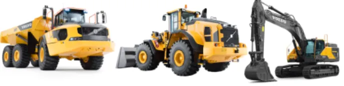
Volvo CE develops and manufactures off-road construction machinery such as articulated haulers, excavators, wheel load-ers, as shown in Figure 1. All construction machinery share a common engine platform. The common platform is outsourced to a technology provider within the Volvo Group. The Engine
Fig. 1. Volvo CE Machinery
Department of Volvo CE then extends the platform for Volvo CE specific applications. The required engine behavior and performance are vastly different between applications. For example, in the articulated hauler, the engine is connected to a transmission, while in an excavator, the engine is connected to a hydraulic pump. In addition to the variable requirements from product platforms (e.g. excavators, haulers), the engine system must fulfill legal requirements for exhaust emissions and diagnostic services in different legislation regions (US, EU, China, and non-regulated markets).
The technology provider develops both the base engine hardware (a bare-bones engine system) and engine control software. To adapt the base engine for Volvo CE specific applications, auxiliary components, such as sensors, oil filters, turbochargers, and cooling fans, are developed at the Engine Department and added to the base engine. Consequently, the software configuration parameters are adjusted to enable or disable software features that control the installed auxiliary components. The software then needs to be calibrated to meet engine performance requirements (e.g. max engine power and torque response) at the Engine Controls Department at Volvo CE. In order to cope with the increasing complexity of both the base engine platform and the auxiliary components, the Engine Department of Volvo CE is in the process of adopting an MBSE approach based on SysML. The aim is to bring together the two different engineering domains: hardware (physical en-gine and auxiliary components) and software (enen-gine controls software). However, one of the major factors that have to be considered during systems engineering at the Engine Controls department is the fact that engine systems must support a large number of variants. At the moment, SysML does not provide a means to document variability within models.
As the models at the Engine Controls department include requirements, system structure and behavior, the system mod-eling approach must support variability on all SysML diagram types. Moreover, the approach must allow one to trace a feature at different abstraction levels, e.g. from requirements to behavior specifications to individual software parameters.
III. SOLUTION
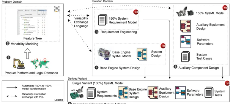
In order to address the needs of organizations that are developing variable products, such as the described Volvo CE example, we present an approach that combines PLE and model-based development in a common process. Figure 2 illustrates the proposed approach. The left side in the figure depicts the problem domain where the variability in the system, the relations and the constraints between variable features are
Fig. 2. A generic approach for combining variability modeling with system modeling
described. In our approach, we propose the use of feature models, which are both documented extensively in literature ([12], [13]) and applied in industrial practice [3].
Once the system variability is described in the variability model, the variability must also be implemented in the solution domain. The middle part of Figure 2 depicts the solution domain. This is where the system models of both common and variable features are developed.
To document variability in models we use 150% models ( [14], [15], [16]) i.e. all system variants are modeled within a single over-specified model. The 150% approach to product lines has the potential to increase product quality, reduce amount of artifacts that need to be maintained, reduce lead-time, etc. [17]. The 150% model contains all system variations within a single model. It is important to consistently exchange variability information between the problem and solution domain. In our proposed tool chain, we use the Variability Exchange Language to integrate the design and variability management tools (cf. Section IV).
Variability models serve as a starting point for customers during the definition of a product variant. Customers select variable product features based on their needs. Constraints and relations between features restrict how features can be combined. The variability information then needs to be ex-changed with the system modeling tool that contains the 150% model. The system modeling tool should then be able to generate a 100% system model of a single system variant. As illustrated in the right part of Figure 2, the derived model should include only model artifacts from the solution domain that were selected during feature selection. For example, these can be requirement models, system architecture, verification procedures, etc.
Since different organizations may have different systems engineering processes and use models at different levels of the process, we strive that our approach is generic enough to be applicable to any phase of their systems engineering process by making it possible to model variability on any diagram type, e.g. requirement models, structure, behavior, etc.
IV. TOOLCHAIN
This section describes a tool chain that supports the ap-proach discussed in the previous section.
In the tool chain, we use the pure::variants tool from pure-systems [18] to manage variability in the problem domain and the Modelio [19] modeling tool to model the
Fig. 3. Product Line Engineering Process with the Model-based Tool Chain
system in the solution domain. In order to integrate the two tools, the Variability Exchange Language was used. It allows us to exchange variability information between the problem and solution domain. pure::variants, as a variability management tool, already supported VEL. However, Modelio had to be extended with mechanisms to support modeling of variability in system models and to exchange information via VEL.
In Figure 3, we illustrate the proposed tool chain workflow in more detail in the context of a Volvo CE use case. It covers several phases of an engine development process starting with requirements and continuing with system design and verification, to some extent.
In Step 1 , customers (product platforms) define their requirements on the system, e.g. needed torque, power, engine start/stop function, etc. In addition, depending on the legisla-tion region in which the customer plans to use the engine, the exhaust emission and diagnostic requirements are varying.
In Step 2 , based on their requirements, customers se-lect system features from the feature model with the pure::variantstool, as illustrated in Figure 4.
pure::variantsis a variability management tool sup-porting VEL to facilitate product line development. As de-picted in Figure 4, a feature model is specified to document all variability of the product line. A set of system features and the possible variants of the feature are shown. The example shows the variability of the Urea Dosing System (UDS) which is a subsystem of the engine. A single UDS consists of a Diesel Exhaust Fluid (DEF)1 storage tank, a pump that pressurizes the DEF and and injection nozzle through which
1DEF is a mixture of urea and water that chemically reacts with exhaust
gases to reduce harmful emissions.
the DEF is dispersed into the exhaust stream. There are also a DEF quality sensor and a valve that controls engine coolant circulation throughout the system in order to defrost it at low temperatures. An actuator control unit (ACU) is used to control the pump in the system.
The constraints between features are defined manually by system engineers during the system design. The variability management tool only defines and manages the system feature model without any other knowledge about how the features are implemented. The feature model and feature constraints
Fig. 4. Feature Model example
restrict the variability space of the system, reducing the risk of creating a variant with incompatible features. Some users might have requirements that are outside the scope of the current product family, i.e. a feature not present in the current set of features. In such a situation there are two possibilities: (i) extend the product line to include the new feature or (ii) implement the new requirement only for the individual variant. Both possibilities will be discussed later in this section. Once
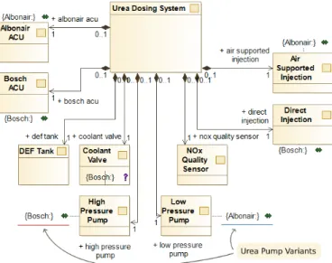
Fig. 5. Annotated SysML model
the feature selection is finished, the variability information from pure::variants (Step 2 ) is exchanged with Mod-elio through the VEL.
Modelio is an extensible UML/BPMN/SysML modeling tool. A module has been developed to extend the tool and allow variability information annotation on top of any kind of supported modeling language (e.g. UML/SysML in our context). As shown in Figure 5, a SysML Block Definition Diagram (BDD) of the UDS is annotated with variability information. It is a desensitized diagram that includes two variants of the UDS. The blocks of the two variants are annotated as ’Bosch’ and ’Albonair’ in Figure 5.
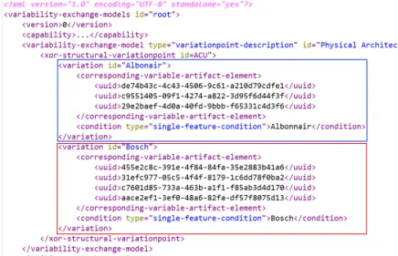
In order to exchange information between Modelio and pure::variants, Modelio first generates a serialized XML file in the VEL, as depicted in Figure 6. The XML file contains information of the 150% model. For simplicity purposes, we show one variation point, named ’Physical Architecture’, with two possible variants, named ’Albonair’ and ’Bosch’, together with information of model elements that belong to either feature. The VEL file is then read by pure::variants and mapped to the feature diagram shown in Figure 4. Mapping is done through a naming conven-tion based on the prototype implementaconven-tion of the variability modeling functionality in Modelio. The features that the user did not select in Step 2 are then removed from the VEL file in pure::variants and a new VEL file is then generated. This new file contains information with the feature set of a single variant, i.e., a 100% file. Modelio uses the new VEL file as an input for a model transformation where elements not contained in the VEL file of a single variant are removed from the 150% system model. As an example, in 3 all product family requirements are contained. Modelio, performs a model transformation based on the VEL file exchange to generate a 100% requirement modelthat is stored separately into 6 .
The requirements define the performance and driveability
goals of the base engine system and auxiliary components. For example, the duration of the engine warm-up function when operating in cold conditions.
The base engine software features and interfaces are con-figured in 4 . As all engine variants are built on a single engine platform, it is necessary to enable or disable software functions and system interfaces based on the application. The configuration is performed by enabling or disabling software parameters. The derivation of software configuration param-eters is again automated based on the same feature selection from 2 and the single variant model elements are again stored into the new model repository, 6 .
Finally, in 5 it is necessary to select appropriate engine auxiliary components (sensors, oil tanks, hoses, radiators, etc.) and configure software functions that control these. Again, based on the feature selection from 2 , the annotated 150% model(containing the all auxiliary component design, software parameters, and tests) is transformed to remove all features that were not selected and generate a 100% model containing only the selected elements.
The variations in requirements, base engine, and auxiliary components are resolved and an individual model is generated and stored in a new model repository in 6 . This final system model then drives the engine assembly and activities such as performance calibration.
Now looking back at the case when customer requirements can not be mapped to any feature in the product line. The first possibility is to extend the product line and implement the required feature. That is, the feature model in 2 must be extended to include the new feature. Then, the requirements in 3 and system design in 4 and 5 must be extended to implement the new feature. The process from selecting variants in the feature model to product derivation needs to be performed again to derive the new variant. The second possibility is to select the closest possible variant in 2 , then once a product based on the feature selection is derived in 6 , it is modified to implement the new requirements. The first approach develops the new feature to be reusable in new projects in the future, while the second approach develops the feature for only one variant.
V. DISCUSSION
We first discuss the approach based on the quality criteria for product lines as defined in [20].
Pre-planning effort. Implementing product lines always requires some pre-planning, at least to define the scope of the product line. System models are often created iteratively and as it is with annotative approaches in general ([20]), our approach enables the product line to be annotated as system models are evolving with little pre-planning. However, it is important to consider that no or little pre-planning might require significant effort to implement new features in later stages, as it might require large parts of the product to change.
Feature traceability evaluates support for mapping of fea-tures between the feature model and implementation models. The use of VEL for exchange of variability information allows
Fig. 6. Generated VEL
us to trace the features from the feature model directly to system model elements. VEL also allows us to trace a feature to multiple SysML models and model elements. That is, a feature can be mapped to any number of model elements that implement the given feature.
Separation of concerns, i.e. capability of the tool chain to support a separation between variable aspects of system features. Traditionally, in model-based development, views and viewpoints are used to express different concerns of the system design [21]. A view is a representation of the system from a perspective (viewpoint) of a stakeholder of a related concern. With SysML, a view can be considered as a set of model diagrams that allow the users to visualize, analyze and reason about a specific system concern or feature [22]. Separation of concerns mainly depends on the implementation of the system, i.e. whether the system is organized into cohesive components. Cross-cutting concerns, for example, the diagnostic function of the engine, however, span across multiple system components. In such cases, annotating model elements with variability information explicitly exposes the cross-cutting features.
Information hiding, i.e. separation of a component into its internal logic and external interfaces is inherently supported in SysML. Since our tool chain supports annotation on any model element, encapsulated model elements of any feature can be annotated with variability, thus enabling information hiding with regards to features.
Granularity, i.e. the level of detail at which variability can be implemented in system models. Our proposed annotative approach provides fine-grained granularity. That is, it allows annotation on all model element types and properties of such elements, as well as annotation on the relationship links between elements.
Uniformity states that variability in all product line artifacts should be encoded consistently. Our tool chain provides good uniformity as all product artifacts are SysML model elements and are annotated in the same fashion.
Based on the initial application, it was noted that the feature model and the constraints between features improve the consistency of system variants as the constraints restrict the possibility to create an invalid variant. The requirement elicitation time from customers (product platforms in the Volvo CE case) can be reduced since customers do not need to interact with domain experts to define a system variant except in the situation when customer requirements can not be mapped to any feature. This situation was described in Section IV. The feature model also received positive feedback from managers and non-technical stakeholders as it allowed them to understand the implications of certain system variants without needing extensive technical knowledge of the system or the domain.
VI. RELATED WORK
MBSE with SysML has been widely used in the industry in various domains, for example, aerospace [6] and automo-tive [23]. SysML can be extended with profiles and stereotypes to support variability [24]. This approach does not require a separate variability management tool. However, compared to our approach, it does not support the modeling of variability in SysML behavior diagrams, which are an important part of the system design. Another approach for modeling variability with SysML is presented in [25]. But again, it is not clear how variability is captured in behavior models. As stated in an literature survey, [8], activity and state machine diagrams are widely used in systems engineering. Thus, it is important to be able to define variants in behavior models as well.
The pure::variants tool was applied in a number of studies and industrial examples such as: [17] [26]. The later being interesting to us as it uses VEL to add variability information on software code. Combining our approaches would allow to have feature traceability through the complete development cycle of a system, from requirements to the system design and then the actual system implementation.
Another use of the same variability management tool and VEL is reported in the experience report in [27]. It describes a methodical and tooling approach with similar concepts to ours. However, their approach uses a custom-built tool to support variability in the problem domain throughout the complete application lifecycle.
Feature modeling, of course, is not the only approach and many of them are compared in [28]. For example, model views can also be used to handle variability in a modeling context [29]. Another study suggests Orthogonal Variability Modeling for variability management in SysML models [30]. Nevertheless, feature-modeling seems to be the most popular one based on a survey with industrial practitioners [3].
VII. CONCLUSION
MBSE is a common approach in practice for the de-velopment of complex, software-intensive systems. However, as presented in the Volvo CE example, organizations face challenges where many similar products must be developed and maintained for different customers. To deal with the highly variable systems, PLE is often applied. To combine the benefits of both worlds, PLE and MBSE, we have presented an approach that allows us to integrate variability information into design models of complex systems. The approach is supported by our tool chain for which we extend the Modelio system modeling tool to support variability modeling in SysML models. In addition, we use the VEL to exchange variability information with the pure::variants tool for variability modeling and management. The approach is demonstrated through an example from Volvo CE. The initial application suggests a potential improvement in efficiency of the engine development process.
ACKNOWLEDGMENT
This work has received funding from the Electronic Com-ponent Systems for European Leadership Joint Undertaking under grant agreement No. 737494. This Joint Undertaking receives support from the European Union’s Horizon 2020 research and innovation program and from Sweden, France, Spain, Italy, Finland and Czech Republic. This work was also partially funded by the ITEA3 15010 REVaMP2 project: FUI the le-de-France region and BPI in France.
REFERENCES
[1] F. van der Linden, Development and Evolution of Software Architectures for Product Families. Springer, 2012.
[2] L. Wozniak and P. Clements, “How automotive engineering is taking product line engineering to the extreme,” in Proceedings of the 19th Intl. SPLC, pp. 327–336, ACM, 2015.
[3] T. Berger et al., “A survey of variability modeling in industrial practice,” in Proceedings of the Seventh International Workshop on Variability Modelling of Software-intensive Systems, VaMoS ’13, (New York, NY, USA), pp. 7:1–7:8, ACM, 2013.
[4] J. L. Barros-Justo, F. B. Benitti, and S. Matalonga, “Trends in software reuse research: A tertiary study,” Computer Standards Interfaces, 2019. [5] A. L. Ramos, J. V. Ferreira, and J. Barcel, “Model-based systems engi-neering: An emerging approach for modern systems,” IEEE Transactions on Systems, Man, and Cybernetics, Part C (Applications and Reviews), vol. 42, pp. 101–111, Jan 2012.
[6] H. Andersson et al., “Experience from introducing unified modeling language/systems modeling language at saab aerosystems,” Systems Engineering, vol. 13, no. 4, pp. 369–380, 2010.
[7] J. Holt and S. Perry, SysML for systems engineering, vol. 7. IET, 2008. [8] S. Wolny et al., “Thirteen years of sysml: a systematic mapping study,”
Software & Systems Modeling, May 2019.
[9] M. Schulze and R. Hellebrand, “Variability exchange language-a generic exchange format for variability data.,” in Software Engineering (Work-shops), pp. 71–80, 2015.
[10] W. Afzal et al., “The MegaM@Rt2 ECSEL Project: MegaModelling at Runtime - Scalable Model-Based Framework for Continuous Develop-ment and Runtime Validation of Complex Systems,” Microprocessors and Microsystems, vol. 61, pp. 86 – 95, 2018.
[11] A. Sadovykh et al., “REVAMP: Challenges and innovation roadmap for variability management in round-trip engineering of software-intensive systems,” Revue G´enie Logiciel, pp. 32–36, May 2017.
[12] K. Lee, K. C. Kang, and J. Lee, “Concepts and guidelines of feature modeling for product line software engineering,” in International Con-ference on Software Reuse, pp. 62–77, Springer, 2002.
[13] M. Sinnema and S. Deelstra, “Classifying variability modeling tech-niques,” Information and Software Technology, vol. 49, no. 7, pp. 717– 739, 2007.
[14] K. Czarnecki and M. Antkiewicz, “Mapping features to models: A template approach based on superimposed variants,” in International conference on generative programming and component engineering, pp. 422–437, Springer, 2005.
[15] F. Heidenreich, J. Kopcsek, and C. Wende, “Featuremapper: mapping features to models,” in Companion of the 30th international conference on Software engineering, pp. 943–944, ACM, 2008.
[16] S. Mann and G. Rock, “Dealing with variability in architecture descrip-tions to support automotive product lines: Specification and analysis methods,” in Proc. embedded world Conference 2009, pp. 3–5, 2009. [17] D. Beuche, M. Schulze, and M. Duvigneau, “When 150% is too much:
supporting product centric viewpoints in an industrial product line,” in Proceedings of the 20th Intl. SPLC, pp. 262–269, ACM, 2016. [18] D. Beuche, “Variants and variability management with pure:: variants,”
in 3rd SPLC, Workshop on Software Variability Management for Product Derivation, Boston, MA, 2004.
[19] Q. I. S. A. Bagnato A., Brosse E., “High level methodologies in embedded system design,” in 2014 Embedded World Conference, 2014. [20] S. Apel et al., Feature-oriented software product lines. Springer, 2016. [21] A. Cicchetti et al., “Chess: a model-driven engineering tool environment for aiding the development of complex industrial systems,” in Proceed-ings of the 27th IEEE/ACM International Conference on Automated Software Engineering, pp. 362–365, ACM, 2012.
[22] “IEEE Recommended Practice for Architectural Description for Software-Intensive Systems,” IEEE Std 1471-2000, pp. 1–30, Oct 2000. [23] H. G. C. G´ongora, T. Gaudr´e, and S. Tucci-Piergiovanni, “Towards an architectural design framework for automotive systems development,” in Complex Systems Design & Management, pp. 241–258, Springer, 2013. [24] T. Weilkiens, Variant modeling with SysML. Lulu. com, 2012. [25] S. Meacham et al., “Sysml based design for variability enabling the
reusability of legacy systems towards the support of diverse standard compliant implementations or standard updates: the case of ieee-802.15. 6 standard for e-health applications,” EAI Endorsed Transactions on Pervasive Health and Technology, vol. 2, no. 5, p. e1, 2016.
[26] J. Rubin, K. Czarnecki, and M. Chechik, “Managing cloned variants: a framework and experience,” in Proceedings of the 17th Intl. SPLC, pp. 101–110, ACM, 2013.
[27] R. Pohl et al., “Variant management solution for large scale software product lines,” in Proceedings of the 40th International Conference on Software Engineering: Software Engineering in Practice, ICSE-SEIP ’18, (New York, NY, USA), pp. 85–94, ACM, 2018.
[28] M. Sinnema and S. Deelstra, “Classifying variability modeling tech-niques,” Information and Software Technology, vol. 49, no. 7, pp. 717 – 739, 2007.
[29] H. Bruneliere et al., “A Feature-based Survey of Model View Ap-proaches,” Software & Systems Modeling, vol. 18, no. 3, pp. 1931–1952, 2019.
[30] D. Bilic et al., “Model-based product line engineering in an industrial automotive context: An exploratory case study,” in Proceedings of the 22Nd Intl. SPLC - Volume 2, SPLC ’18, pp. 56–63, ACM, 2018.