HAL Id: hal-01620291
https://hal.archives-ouvertes.fr/hal-01620291
Submitted on 15 Feb 2019
HAL is a multi-disciplinary open access
archive for the deposit and dissemination of
sci-entific research documents, whether they are
pub-lished or not. The documents may come from
teaching and research institutions in France or
abroad, or from public or private research centers.
L’archive ouverte pluridisciplinaire HAL, est
destinée au dépôt et à la diffusion de documents
scientifiques de niveau recherche, publiés ou non,
émanant des établissements d’enseignement et de
recherche français ou étrangers, des laboratoires
publics ou privés.
Experimental and numerical analysis on drilling of
carbon fibre reinforced plastic and aluminium stacks
Redouane Zitoune, V. Krishnaraj, Francis Collombet, Sabine Le Roux
To cite this version:
Redouane Zitoune, V. Krishnaraj, Francis Collombet, Sabine Le Roux. Experimental and numerical
analysis on drilling of carbon fibre reinforced plastic and aluminium stacks. Composite Structures,
Elsevier, 2016, 146, pp.148-158. �10.1016/j.compstruct.2016.02.084�. �hal-01620291�
Experimental and numerical analysis on drilling of carbon fibre
reinforced plastic and aluminium stacks
R. Zitoune
a,⇑, V. Krishnaraj
b, F. Collombet
a, S. Le Roux
caInstitut Clément Ader (ICA), IUT-A of Toulouse Université, 133c, avenue de Rangueil, 31077 Toulouse cedex, France bDepartment of Production Engineering, PSG College of Technology, Coimbatore 641004, India
cUniversité de Toulouse; CNRS, Mines Albi, INSA, UPS, ISAE-SUPAERO; ICA (Institut Clément Ader); Campus Jarlard, F-81013 Albi, France
Keywords: Machining
Finite element analysis (FEA) CFRP/Al stacks
a b s t r a c t
In this paper, experimental and numerical study of drilling of carbon fibre reinforced plastic (CFRP) lam-inate with aluminium alloy stacks has been carried out. Drilling of these multi-materials is a challenging task to manufacturing engineers because of different mechanical properties of materials. In this work, the impact of the machining parameters on the effect of twist drill and the geometry of double cone drill on cutting forces, holes quality and on CFRP/Al interface have been investigated. From the experimental study, it was found that the double cone drills induce less thrust force compared to the standard twist drill. From the numerical analysis based on the linear fracture mechanics of the CFRP and the plastic behaviour of the aluminium with isotropic hardening, on the one hand, the critical thrust force respon-sible for the delamination of the last ply as a function of the aluminium thickness has been identified and on the other hand, the maximum thrust force responsible for the interface separation of CFRP/Al has been predicted as a function of the aluminium thickness.
1. Introduction
Drilling and fastening of the CFRP & metals in one-shot opera-tion reduce manufacturing time in building aircraft structures. The most common problems encountered during automatic dril-ling of CFRP/metal structures (composite/titanium or composite/ aluminium) are (i) the damage on the composite material due to the interaction between the continuous metallic chips and the sur-face of the composite material, (ii) the high thrust force induced during drilling can separate CFRP and aluminium plates which con-tribute to the accumulation of aluminium chip and carbon dust at the interface of CFRP/Al, and finally (iii) the adhesion of the metal-lic layer on the cutting edge of the tool. LATECIS, a French company in Toulouse, has developed a system called OPERA, which is dedi-cated for one shot drilling. Ideally the OPERA system is expected to handle high production rates (1 attachment mounted approxi-mately at every 12 s)[1–3]. The automation of these tasks must also enable greater mounting precision, improved ergonomics, health and safety of the operators, particularly for the new hybrid materials like composite/titanium or composite/aluminium assem-blies. Due to the different mechanical properties of materials
constituting the hybrid panels, their machinability remains an open problem and can prevent the automation of these tasks.
From the literature, it is found that the composite materials, especially CFRP’s are often used to a larger extent due to their downsizing and rightsizing impacts. However, due to their lami-nated structure and the anisotropy of the carbon fibre reinforced plastics several damage modes are seen during drilling. These damage types are peel up delamination at the hole entry, thermal alteration, fibre pull-out and fuzzing on the wall of the hole, and exit delamination and uncut fibre at the hole exit[4–6]. Moreover, the mechanism of material removal in composite materials is strongly influenced by the relative angle between the direction of the cutting speed and the direction of orientation of fibre [7,8]. Sakuma et al. [9] drilled holes by using four drill bit materials and investigated drill wear pattern, flank wear width and cutting forces. Few researchers investigated the effect of tool geometries on drilling of polymer composite materials. Many of the modified geometries (Zhirov point, Brad and Spur, step drill, candle stick, saw drill, etc. (Ref.Fig. 1)) are difficult to regrind[10–12]. Krish-naraj et al.[10]drilled composites at high spindle speed and stud-ied the influence of tool geometries. They reported that double cone drill offers better surface finish when compared to standard twist drill and Brad & Spur drill. This result is in good agreement with the work of Zitoune et al.[12]while drilling of carbon/epoxy ⇑Corresponding author.
laminate with different geometries of double cone drills. It was reported that double cone drills with the length of the principal cutting edge is equal to the length of the secondary cutting edge offer lesser thrust force and better surface finish[12]. In addition, the obtained machining quality has been correlated to the mor-phology of the chips which is mainly influenced by the feed and composition of the thermosetting resin. In fact, the resin which characterises the composite ply contains uniform micro-layer of thermoplastic which leads to improve the machining quality and the formation of continuous chips. With the absence of this ther-moplastic layer, the result obtained by Haddad et al. [13] and Ramulu et al.[14]have shown that the amount of carbon dust par-ticles present (between 0.25
l
m and 1l
m) in the air are higher. In addition, it was mentioned that the size of most of the particles in the air generated at different cutting conditions (conventional machining or high speed machining) and using different tool geometries are ranging between 0.25l
m and 0.7l
m. These carbon dust particles are not influenced by the wear state of the cutting tool. However, increase in flank wear increases the thrust force and decreases the machining quality[15–21]. The loss of machin-ing quality can be observed by the appearance of delamination at the hole exit and/or the increased roughness values on the wall of the holes. Cadorin et al.[21]reported that even at high thrust force and wear the presence of the reinforcement in the third direction of the laminate (e.g. composite 3D) resists the initiation of delamination at the hole exit. When 3D composite is drilled even if the thrust force is higher, no delamination was observed at the hole exit for the various tool geometries tested (core drill or three lips twist drill)[22].Unlike composite materials, the material removal during machining of aluminium or titanium is mainly induced by shearing phenomena. In the case of drilling of these kinds of isotropic mate-rials, the main problem is the adhesion of aluminium or titanium on the main cutting edges called built up edge (BUE) on the rake face and on the flutes of the drill. In fact, this bonding is responsible for premature wear of the cutting tool for the poor surface finish of the hole and the variations in the diameter of the hole. Several authors showed at low cutting speeds (up to 25 m/min) bonding of aluminium occurring at the rake face and at the main cutting edges[23–26]. Because of the high adhesion affinity of the alu-minium alloy with the drill tool, high feed was used during deep hole drilling of aluminium alloy using MQL (Minimum quantity lubrication)[24]. To improve the drilling quality and efficiency of machining, aluminium alloy nano-coated drills were used [25]. Another way to overcome problems related to the machining of aluminium and its alloys are to increase cutting speeds. However, machining at high cutting speeds (e.g. 300 m/min) cause a signifi-cant increase in the cutting temperature (above 300!C). At this
temperature, a chemical reaction between aluminium and cobalt occurs to form micro welding of aluminium on the cutting edges of the tool by diffusion.
Additionally, when drilling multi-stacks (e.g. CFRP/Al or CFRP/ Ti), shape of metallic chips and length of the chip passing through the hole as well as built up edges of aluminium (or titanium) at the primary cutting edges combined with increased tool wear affect the hole quality[27–30]. In this situation, small and broken chips are recommended to obtain better quality of the hole. To break the chips into small segments, authors [1–3] recommended to use a feed of 0.1 mm/rev and a spindle speed around 2500 rpm, when drilling is conducted with a twist drill of 6 mm diameter. Another solution proposed by the same authors is the use of nano-coating. With nano coating (e.g. nc-CrAlN/a-Si3N4), it has been shown that the roughness of the wall of the hole and the thrust force in the composite were reduced respectively by 30% and 20% during dry drilling of CFRP/Al. In[29,30], authors studied drilling of Gr/Bi–Ti in the context of process conditions and cost optimisation. The obtained results show that with the carbide twist drill it is preferable to drill with a small spindle speed (lesser than 1000 rpm) and feed of around 0.08 mm/rev. Numerical pre-diction of delamination in drilling is reported by few researchers
[31,32]. Drilling of FRP using various geometries and using wide range of spindle speeds have been reported extensively in the lit-erature[33–36]. Xu et al.[37]reviewed the issues related to dril-ling of FRP/metal stacks. They concluded that the interface drilling is the complex and challenging task. Acoustic emission sig-nals were used to monitor the position of drill in FRP/metal stack to change the process parameters during drilling[38]. Drilling force and wear phenomena during drilling of FRP/metal stacks were reported by Poutord et al.[39]. Quality of the hole during drilling of metallic/FRP stacks were reported by few researchers[40–42]. The major issues during drilling of these stacks are tool wear, qual-ity of the machined surface and burr formation between the stacks
[43–46]. Drilling of FRP/metal stacks with high quality is a chal-lenging task[37–46]. Few papers reported the effect of machining parameters on the hole quality. The major issues during drilling of these stacks are wear of the tool, quality of the machined surface and burr formation between the stacks. The approach towards dril-ling multi-materials is to increase the tool life and quality of the holes. Among the various tool geometries investigated during dril-ling of aluminium or composite, double cone drill was found to offer many advantages when compared to the modified geome-tries. Among the various tool geometries investigated during dril-ling aluminium alone or composite alone, double cone drill was found to offer many advantages when compared to the modified geometries. Only a few investigations on drilling of CFRP laminates using double cone drill have been reported and no information is
Fig. 1. Various drill geometries used in drilling (a) standard twist drill, (b) step drill, (c) Brad point drill bit, (d) straight flute drill bit (dagger), (e) multifaceted drill bit and (f) core drill/trepanning tool.
available about this kind of tool when drilling FRP/metal stacks. In addition, it is found in the literature that the double cone drills are optimised for drilling of metallic materials (steel or aluminium). However, there is little information about the influence of the geometry of the double cone drill on the quality of holes machined. In this paper, experimental study on drilling of multi-material made of CFRP laminate with aluminium plate has been carried out. These drilling tests have been conducted using carbide drills (K20) to study the influence of spindle speed, feed and lip length of the double cone drill on cutting forces and quality of holes. The objectives are to identify the better machining parameters and the tool geometry, which are able to machine with respect to the industrial criteria imposed by Latecis Company, France. The criteria set are discontinues aluminium chips, roughness of the wall of the holes has to be lesser or equal to 1
l
m in aluminium alloy and 3l
m in the composite part. In order to predict the mechanical behaviour of the CFRP/Al interface vs. the applied load (measured thrust force) and the critical thrust force which can induce delamination of the last ply of the CFRP, two numerical models are proposed. The main goals of this numerical analysis are on the one side, prediction of critical thrust force responsible for the delamination at the exit side of hole as a function of the thickness of the aluminium plate placed beneath the CFRP lami-nate and on the other side, to investigate the impact of maximum measured thrust force on the separation of CFRP/Al interface as well as the probability to increase the accumulation of the carbon dust at the interface.2. Experimentation and procedure 2.1. Materials
The multi-material stacks used in this study are composed of composite and aluminium. The composite specimen used in the investigation was 4.2 mm thick. The composite parts are composed of 16 unidirectional plies of 0.26 mm thickness each. The 16 unidi-rectional plies are made of carbon/epoxy prepregs (T700-M21) manufactured by Hexcel Composite Company. The staking sequence used is of [90/45/0/-45]2s. These materials were com-pacted using a vacuum pump in a controlled atmosphere. A mould for the laminate was prepared and placed in a vacuum bagging and evacuated to 0.7 bar (Ref.Fig. 2) Curing was then carried out at 180!C for 120 min during which the pressure was maintained at 7 bar in an autoclave. The mechanical properties of the ply T700-M21 are detailed in[31]. The aluminium alloy used in this study is extensively used in the civil or military aircrafts and is
referenced as Al 2024. The percentage of alloying elements is as follows: Al 93.5% Si 0.5%, Cu 3.8–4.9%, Mg 1.2–1.8%, 0.1% Cr. 2.2. Drilling process
Drilling is carried out on a CNC machine developed by LATECIS Company (Toulouse, France) under the research project OPERA (Automated drilling and riveting of aircraft structures) is shown inFig. 3a. The acquisition of cutting forces is carried out using a four component Kistler dynamometer shown in Fig. 3b. The dynamometer is connected to a Kistler charge amplifier Type 5019. The output of the amplifier is transformed into a cutting force through a computer that stores the force signals versus cut-ting time. The CFRP/aluminium panel to be drilled is clamped on a dedicated support (seeFig. 3b). On the fixture, a hole of 18 mm is machined to allow the drill bit and to prevent the bending of the multi-material. The drilling tests performed are based on full factorial experimental design using three feeds (0.05 mm/rev, 0.1 mm/rev and 0.15 mm/rev) and two spindle speeds (2020 rpm and 2750 rpm).
Values of spindle speeds used in this study represent on the one hand the maximum values available with the machine tool used and on the other hand the limiting values available with automatic drilling unit (electric) commonly used in Airbus. Moreover from the previous studies carried out by the authors, it is found that spindle speed has less effect on the quality of the hole[2]. High spindle speed reduces the life of the drill and not suitable for CFRP. Hence these two spindle speeds (2020 rpm and 2750 rpm) are selected.Table 1presents the experimental conditions.
2.3. Cutting tools
For this work, four batches of tool geometries have been used. The first batch is a set of conventional twist drills referred under the name reference drill. The characteristics of reference drills marketed by French industries for drilling of composite materials for Airbus is presented inFig. 4a. Other batches of tools are double cone drills. These double cone drills are referenced under the names double cone M1, double cone M2 and double cone M3 for batches 2, 3 and 4 respectively. Double cone drills are easier to regrind when compared to special geometries (Ref.Fig. 1). These double cone geometries have been obtained after grinding the ref-erence tools. This grinding operation is achieved using a 5-axis grinding machine. The form of the double-cone tool geometry is represented in the Fig. 4b. The double cone tools measure 90! and 132! point angles with cutting edge lengths, namely L1 and L2 (Ref.Fig. 4b) while L1 represents the size of the principal cutting edge number 1 which is characterised by a point angle of 132! and L2 represents the size of principal cutting edge number 2 which is characterised by a point angle of 90!. The double cone drills tested are ground with different L1/L2 ratios, in which M1, M2 and M3 are characterised by the L1/L2 ratios of 0.33, 1 and 3.1 respectively. All the drills tested have a 6.35 mm of diameter made of tungsten car-bide (K20). The details about the geometry of the reference drill and the double cone drills are summarised in the Table 2. Each experimental condition was repeated 5 times in order to get con-sistent values. To remove the influence of tool wear, each experi-ment was performed with a new drill. The quality of the machined surface (wall of the hole) is quantified using the SEM observation and the surface roughness systems (with and without contact). For the 3D surface topography of the wall of the holes, a 3D optical profilometer has been used. The parameter Ra which characterises the surface roughness of the hole was measured by the Mitutoya SJ 500 roughness tester with a sampling length (cut-off) of 0.8 mm. In case of CFRP, the length of measurement through the hole was 4 mm (0.8 ! 5 = 4 mm) and for the Vacuum
Sensors to monitor temperature Rigid mould
aluminium, the length of measurement through the hole was 2.4 mm (0.8 ! 3 mm). Finally to analyse whether delamination is present or not at the exit side of the hole of CFRP plate, an X-ray micro computed tomography was carried out by using Micro-Tomography Easy Tom 130 machine. The X-ray voltage and current were set as 130 kV and 300 mA respectively.
3. Results and discussions 3.1. Experimental results 3.1.1. Analysis of cutting force
Fig. 5 represents the evolution of the average values of the thrust force recorded in the composite and in the aluminium as a function of feed rate, for different geometries tested. From these average values of forces, it can be observed that drilling of compos-ite material with the reference tool induces a higher thrust force compared to the double cone drills (Ref. Fig. 5a). For example, when the feed is increased from 0.05 mm/rev to 0.15 mm/rev, dril-ling with the reference tool generates higher thrust force and increases from 80 N to 123 N. However, when the double cone drills are used at the same machining parameters, the generated forces are lesser compared to those generated with the reference drills. In addition, the thrust force generated by the double cone drills in the composite material decreases while L2/L1 ratio of the tool increases (15%–30% lesser). This can be explained by the fact that by adding a secondary point angle of 90! reduces the
theoretical average chip thickness by 15%. It is also well estab-lished in the literature, that (orthogonal cutting on unidirectional composite material) increasing depth of cut (chip thickness) leads to an increased cutting forces. It can be mentioned that during machining with a twist drill, the contact between the surfaces of CFRP and point of the tool projected is more compared to the one between the CFRP and the double cone drills. In addition, this surface contact decreases when the L2/L1 increases. In this case, the frictional forces can also be decreased with the increase of the L2/L1 ratios. In fact, this can be explained based on the reduc-tion of the thrust forces in the composite when the double cone drills with high values of L2/L1 ratios (double cone drills M2 and M3) are used. It is important to note that these results are in good agreement with those observed when drilling of CFRP composite with double cone drills[12].
When the tool starts to machine the aluminium part, the thrust force generated raises steeply to all the tools used at any feed selected. In addition, the form of force signal is similar to those pre-sented in the literature[1–3,28–30]. However, it seems that the average values of the recorded forces are influenced by the tool geometry (Ref.Fig. 5b). From theFig. 5b, it is observed that when the feed is varied from 0.05 mm/rev to 0.15 mm/rev while the standard twist drill (reference drill) is used, the thrust force increases by 158% (with the maximum value of 481 N). When the double cone drills of M2 and M3 are used, similar results are also observed in the evolution of thrust force values compared with the reference drill. However, with the same machining parameters, when the double cone drill M1 is used, it is clear that the recorded forces in the aluminium are inferior to those obtained with the reference drill or the double cone drills of type M2 and M3. In order to understand the influence of the machining and tool parameters on thrust forces, ANOVA technique has been used (Ref
Tables 3 and 4).Table 3presents the effect of various parameters on thrust force during drilling of aluminium alloy. It is found that the ratio of L2/L1 is having less effect on thrust force (2% only).
(a)
(b)
Spindle
Camera
Multi-stacks CFRP/Al
Dynamometer
Fig. 3. Images show the experimental device used for drilling. (a) Global view of the OPERA system (Latecis, France), (b) setup for measuring cutting forces.
Table 1
Machining conditions.
Drilling of Composite–aluminium stacks
CNC machine Spindle power 5 kW
Drilling conditions Spindle speed (rpm) 2020 and 2750 Feed (mm/rev) 0.05, 0.1 and 0.15
)
c
(
)
b
(
)
a
(
L1 L1 L1 L2 L2 2 mm 2 mm 2 mmHowever, this parameter has higher influence while drilling CFRP laminate. It is also found that feed rate has the higher influence on thrust force in both aluminium and CFRP (% of contribution in aluminium is 96% and 83% in the CFRP).
3.1.2. Machining quality
Figs. 6 and 7represent the effect of drill geometry on surface finish at various feed rates for a spindle speed of 2020 rpm in the
CFRP and aluminium respectively. Experimental results reveal that at a low feed rate (<0.1 mm/rev), the quality of the machined sur-face is better for all the drills used. In this case, the measured roughness values are smaller (<3
l
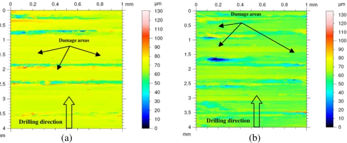
m). Further, it can also be observed that for all machining parameters used the values of the surface roughness obtained with the reference tool are higher when compared to those obtained with double cone drills. This dif-ference can be linked to the interaction between the size of the chip thickness and the point angle of the drill. Refer to the results obtained by[12]when drilling is carried out with the double cone drills and reference drill of composite alone, it has been shown that double cone drills offer better surface finish compared to the refer-ence drill. The work of Zitoune et al.[2]suggests that double cone drills favour the formation of continues chips (better than refer-ence drill) during the drilling of aluminium. For this reasons, lesser roughness values are obtained on the wall of aluminium holes when drilling is carried out by using double cone drills compared to the reference drill. While drilling aluminium with twist drill, the roughness measured on the wall of the holes are higher with the higher feed rate. In addition, by increasing the length of the secondary cutting edge of the double cone drills, the chip thickness can be reduced to improve the machining quality in the aluminium plate (Ref.Fig. 7). Except the double cone drill type M2 in the CFRP, the roughness increases with the increase in L2/L1 ratios. These results can also be confirmed by the topographies of the wall of the holes in CFRP after drilling with reference drill and the double cone drill M2.FromFig. 8, it is noticed that for the entire tools used in CFRP, the defects in form of fibre pull-out and resin degradation is observed on the plies oriented at "45! (or 45!). However, the depth and the width of these defects are higher when the reference drill is used compared to the double cone drill M2. This can be explained by the interaction between the aluminium chips and the fibre pull-out generated during the first phase when the cutting edges of the drill were in contact with the composite plies for the chip formation. This also explains why the roughness obtained with the reference drill at 0.05 mm/rev (Ref. Fig. 6) is higher to the one obtained with the double cone drill type M2.
Mainly, drilling with double cone drill type M2 give better machining quality. Especially, drilling at feed rate of 0.1 mm/rev using the double cone tool (M2) offers a small roughness values in the composite and aluminium holes (roughness in the CFRP infe-rior to 3
l
m and in the aluminium inferior to 1l
m). In addition,Table 2
Characteristics of reference tool and double cone tools used.
Geometric characteristics of tools Reference drill Double cone drill – M1 Double cone drill – M2 Double cone drill – M3
Diameter (mm) 6.35 6.35 6.35 6.35
Web thickness: (mm) 0.16 0.16 0.16 0.16
Point angle No. 1(!) 136 136 136 136
Point angle No. 2(!) – 90 90 90
Clearance angle: (!) 8.58 8.65 8.65 8.65
Helix angle: (!) 32.5 32.5 32.5 32.5
Ratio: L2/L1 0 0.33 1 3.1
Fig. 5. Influence of tool geometry vs. feed rate on thrust force during drilling at a spindle speed of 2020 rpm. (a): thrust force in composite, (b): thrust force in aluminium.
Table 3
ANOVA performed on thrust force measured during drilling of aluminium alloy.
Factors DL Sum of squares Mean square = variance F P-value Contribution (%)
f (mm/tr) 2 467,052 233,526 3939,56 0,000 96 L2/L1 3 6979 2326 39,25 0,000 2 f (mm/tr)⁄L2/L1 6 3207 534 9,02 0,000 1 N (tr/min) 2 590 295 4,97 0,017 0.8 Erreur 22 1304 59 Total 35 479,131
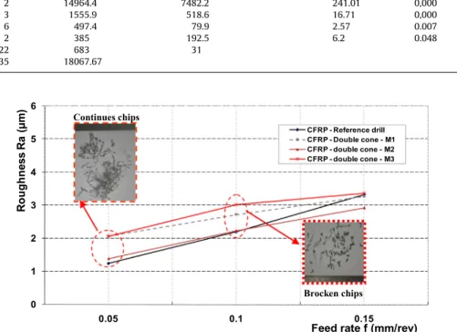
drilling at a feed rate of 0.1 mm/rev favours the generation of dis-continuous aluminium chips (Ref.Fig. 6). The stable surface rough-ness values beyond 0.1 mm/rev could be due to the wiping effect of the primary cutting edge 2. It is important to mention that drilling with a small feed rate (0.05 mm/rev) favours the generation of con-tinues chips for all tools used. With these continuous chips, two problems have been observed when the OPERA system is used.
The first problem is the interaction of the aluminium chips with the composite plies, leads to the degradation of the first ply of the CFRP part located at the hole entry and also increase in the size of fibre pull-out on the wall of the hole (Ref.Fig. 8). The second prob-lem is associated to the vacuum system. During drilling with the OPERA system, it was observed that with the presence of continues chips, the efficiency of the vacuum system is reduced. In this case, the dust quantity in the air increases, which can be harmful to the
health of the operator of the machine. For these reasons, the better solution is to use a feed rate of 0.1 mm/rev, because the aluminium chips are broken and also satisfies the quality of the holes repre-sented by the industry (small roughness and no delamination). At this feed rate, the thrust force is higher (350 N), and during con-tinuous machining because of the wear of the tool this force can double or triple. By knowing the critical thrust force, on the one hand delamination of the last ply may be controlled and on the other hand when the tool start to drill the interface of CFRP/Al, this force may create deflection. Moreover, with the separation of the CFRP/Al interface, the dust particle can accumulate between the stacks and this may impose additional effort to clean the interface before inserting the rivet or the bolt. In fact, the time of manufac-turing increases dramatically. For this reason, two numerical mod-els are proposed in order to predict the critical force responsible for
Table 4
ANOVA results performed on thrust force measured during drilling of CFRP.
Factors DL Sum of squares Mean square = variance F P-value Contribution (%)
f (mm/tr) 2 14964.4 7482.2 241.01 0,000 83 L2/L1 3 1555.9 518.6 16.71 0,000 9 f (mm/tr)⁄L2/L1 6 497.4 79.9 2.57 0.007 3 N (tr/min) 2 385 192.5 6.2 0.048 2 Erreur 22 683 31 Total 35 18067.67 0 1 2 3 4 5 6 0.05 0.1 0.15 Ro ug hn ess Ra (µ m)
Feed rate f (mm/rev) CFRP - Reference drill CFRP - Double cone - M1 CFRP - double cone - M2 CFRP - double cone - M3 Continues chips Brocken chips
Fig. 6. Evolution of the roughness in CFRP vs. feed rate for reference and double cone drills (spindle speed of 2020 rpm).
0 1 2 3 4 5 6 0.05 Ro u g h n es s R a (µ m ) 5 1 . 0 1 . 0
Feed rate f (mm/rev) Al - Reference drill
Al - Double cone - M1 Al - Double cone - M2 Al - Double cone - M3
delamination at the hole exit and the one responsible for the sep-aration of the interface.Table 5summarises the results observed during drilling of CFRP/Al stacks.
3.2. Numerical study
3.2.1. Description of the numerical models
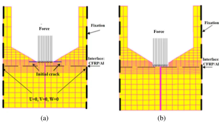
To analyse the impact of the highest measured thrust force with the reference drill (twist drill) on the delamination at the exit side of hole and to identify the behaviour at the interface of CFRP/Al, two numerical models are proposed. The numerical model is a 3D model based on the use of 3D volume composite elements for the carbon/epoxy plate and 3D volume elements for the alu-minium plate. In the first model, which leads to predict the delam-ination at the hole exit, one ply under the tool is considered. In this case, contact between tool and CFRP is modeled as a uniformly dis-tributed load located below the chisel edge of the tool (Ref.Fig. 9a). In addition, a pre-crack with a size of 0.05 mm is considered at the vicinity of the chisel edge. The critical thrust force responsible for the delamination of the last ply is related to the critical energy release rate in mode I and mode II of the CFRP composite laminate. In fact, when the energy release rate in mode I and in mode II pre-dicted by the model satisfy, the criterion mentioned by the equa-tion 1, the applied force corresponds to the critical thrust force.
GI GIC ! "a þ GGII IIC ! "a ¼ 1 ð1Þ where:
- GI: energy release rate in mode I predicted by the model. - GII: energy release rate in mode II predicted by the model.
- GIc: energy release rate in mode I which characterises the inter-face of the material.
- GIIc: energy release rate in mode II which characterises the interface of the material.
-
a
: constant which depends on the nature of the CFRP (herea
= 1.6).The coefficient ‘‘
a
” being an empirical parameter derived from the best fit to data from mixed mode tests. ‘‘a
” is generally in the range of 1–2[48,49]. In this study, the value of ‘‘a
” has been taken based on the previous work of the authors[31]. More precisely, this value is equal to 1.6 as identified by Lévêque[48]for the same material. The second model is proposed in such a way that the chi-sel edge is in contact with the aluminium. For this, the contact between tool/multi-stacks is considered only between the chisel edge of the tool and the aluminium part (Ref.Fig. 9b). In this case, the deflection of the aluminium part below the chisel edge of the tool is analysed by considering load below the chisel edge. The con-tact condition between the tool and the aluminium is considered as a uniformly distributed load with a circular surface area occu-pied by the chisel edge of the tool (1.2 mm). The amplitudes of the applied force are representative of those measured when the drill is fresh and when the tool is considered worn. For the both proposed models, the mechanical behaviour of the aluminium part is considered as a classical plastic with isotropic hardening. This law is described in the work of Peech et al.[47].3.2.2. Numerical results
Fig. 10represents the evolution of the energy release rate in mode I for different level of force. It is clear that with the increase of the applied force, the computed energy release rate in mode I
)
b
(
)
a
(
Drilling direction Drilling direction Damage areas Damage areasFig. 8. 3D Cartographies of the damage located on the wall of the hole after drilling with a feed rate of 0.05 mm/rev and spindle speed of 2020 rpm. (a): drilling with reference drill, (b) drilling with double cone drill M2.
Table 5
Summarises the phenomena observed during drilling of CFRP/Al stacks. Material/drill used Results observed
CFRP/reference Tool
High thrust force (min = 80 N, max = 122 N), roughness Ra < 2lm for feedte <0.15 mm/rev and Ra > 3lm for feed = 0.15 mm/rev CFRP/double cone
drill
Thrust force is mainly <by 20% compared to the thrust force generated by the reference drill
Roughness Ra with double cone drill M2 is smaller to those obtained by the reference drill (Ra < 2lm for feed <0.15 mm/rev). However, Ra obtained with double cone drill M1 and M3 are superior by 50% compared to those obtained with the reference drill
Al/reference tool High thrust force (min = 174 N, max = 486 N), roughness Ra > 1lm for any feed tested. Broken chips are observed when feed is P0.1 mm/rev Al/double cone
drill
Thrust force obtained by the double cone drill M3 is < by 20% compared to other tools. Roughness obtained for any double cone drill is <by 40% compared to the roughness obtained by the reference drill
and mode II increase. For example, when the applied force varies from 100 N to 600 N, the energy release rate in mode I varies from 0.01 N/mm to 0.25 N/mm. These values remain inferior to the crit-ical value when compared to the interface strength of the compos-ite plies which is 0.4 N/mm. This can be attributed to the aluminium plate located at the bottom of the CFRP laminate, which block the bending of the uncut layer of the CFRP and also the prop-agation of the crack. These results can be confirmed when the alu-minium plate thickness is reduced. In fact, when the alualu-minium
part has a thickness of 1 mm with an applied axial load of 400 N, the critical energy release rate in mode I reach the critical value and the delamination can occur (Ref.Fig. 11). The critical thrust force identified previously on the same composite during the quasi-static punching tests using twist drill show that the delami-nation of the last ply under the tool can occur when the critical thrust force reach a value of 395 N[31]. This result confirm that for a thickness of aluminium part less than or equal to 1 mm the bending stiffness (of the aluminium) is low and can’t influence the critical thrust force responsible for the delamination of the last ply of the composite.
In the Fig. 12a and b, cartographies of displacements ((OZ) direction) are illustrated for the applied load of 400 N and for two thicknesses of the aluminium part which are 3 mm and 1 mm respectively. The applied force of 400 N corresponds to the critical value responsible for the delamination of one ply under the tool when drilling of the same material. This force has been identified in the previous study[31]. From these two cartographies of displacement, it is clear that when the thickness of the alu-minium part is inferior or equal to 1 mm, the applied load induces a local bending of the aluminium plate which favours delamination at the hole exit (Ref.Fig. 12a). However, with the increase of the thickness of the aluminium part, the deflection phenomena is less pronounced or inexistent (Ref.Fig. 12b). Thereby, this can remove the probability of the delamination at the hole exit.
When the active part of the drill reaches the interface of CFRP/ Al, the analysis of the CFRP/Al interface shows that for an applied force of 160 N and when zero ply under the tool is considered a
(b)
(a)
Force Force
Fig. 9. Cross section of the 3D model showing the mesh and boundary conditions (a): model with one ply under the tool, (b): model with zero ply under the tool.
0 100 200 300 400 500 600 700 0 0,05 0,1 0,15 0,2 0,25 0,3 T h u rs t f o rce (N )
Energy release rate (N/mm) GI (N/mm) GII (N/mm)
Fig. 10. Impact of the applied thrust force on the predicted energy release rate in mode I and mode II.
0 0,05 0,1 0,15 0,2 0,25 0,3 0,35 0,4 0,45 0,5 1,5 2,5 3,5 4,5 5,5 En er gy re lease ra te (N /m m )
Thickness of Aluminium plate (mm) Energy release rate in mode I (N/mm) Energy release rate in mode II (N/mm)
negligible amount of opening at the interface CFRP/Al is observed. The maximum size of this opening is around 0.23
l
m when the applied load is equal to 160 N (Ref.Fig. 13a). However, when the load reaches 400 N (feed rate of 0.15 mm/rev), the size of this opening increases to 0.38l
m (Ref. Fig. 13b). Haddad et al.[13,14] reported that when machining T700/M21 carbon/epoxy composite material, the major particles generated by the end milling have a size of around 0.45
l
m. In this case, when the applied load is around 400 N, the carbon dust cannot pass through the CFRP/Al interface. Therefore, even in the most unfavorable sit-uation (high feed rate and thrust force), it is not necessary to sep-arate the parts (CFRP and aluminium) in order to clean the interface before to put the rivets. However, if the thickness of the aluminium plate is around of 1 mm, the maximum size of this opening is around 1.23l
m when the applied load is equal to 160 N (Ref.Fig. 13c). In fact, in this situation the set up of the parts separation is necessary in order to clean the interface before to put the rivets. It is important to note that the results of the thrust force measured using the Kistler dynamometer during drilling does not show any drop in the thrust force when the chisel edge reaches the CFRP/Al interface for both small and high feed rates. This may be confirmed by the fact that the predicted forces for delam-ination are higher compared to the measured forces for the feed rates and for the geometry of the twist drill used. In addition to this, the X-ray tomography did not show any delamination defect at the exit side of the hole even for higher thrust force (Ref.Fig. 14a). However, by increase of the feed rate to 0.15 mm/rev, fibre pull-out and matrix degradation is observed (Ref.Fig. 14b).
4. Conclusion
In this paper, the impact of machining parameters and the design of double cone drill on the cutting forces and the machining quality while drilling a multi-stack material made of CFRP laminate and aluminium plate have been investigated. From the experimen-tal and numerical analysis carried out, the following conclusions are drawn:
' From this experimental and numerical study, it can also be con-cluded that the use of aluminium as back plate for CFRP delay the delamination at the hole exit of the CFRP. However, when a thin aluminium plate is used (61 mm), it’s influence is negli-gible on the critical thrust force.
(a)
(b)
Aluminium thikness = 1 mm Aluminium thikness = 3 mmFig. 12. Cartographies of the displacement follow (OZ) direction when 1 ply under the reference tool is considered and an axial force of 400 N. With: (a) thickness of the aluminium part of 1 mm and (b) thickness of the aluminium part of 3 mm.
(a)
(b)
(c)
Aluminium thikness = 3 mm Aluminium thikness = 3 mm Aluminium thikness = 1 mmFig. 13. Cartographies of the displacement in the direction (OZ) when 0 ply under and the reference tool is considered. With (a): applied loading of 160 N and aluminium thickness of 3 mm, (b): applied loading of 400 N and aluminium thickness of 3 mm and (c): applied loading of 160 N and aluminium thickness of 1 mm.
' The feed rate and the drill diameter seem to have an effect on chip breakability because of the increase in cross sectional area of chip whereas effect of spindle speed seems to be smaller. In the drilling operation, small well broken chips are desirable to break the chip of aluminium preferable spindle speed and feed rate seems to be 2020 rpm, 0.1 mm/rev and above[2]. ' When drilling is carried out using double cone drills, the thrust
force measured in the CFRP are lesser compared to the thrust force measured in drilling of CFRP with the standard twist drill. Moreover, when the double cone drill M3 is used, the thrust forces measured in the aluminium are lesser compared to those generated when the twist drill and the other double cone drills (M1 and M2) are considered. Thereby, the design parameter of double cone drill recommended for isotropic material (double cone drill M3) cannot be directly used when drilling of CFRP or CFRP/Al[50].
' When the machining is carried out using the double cone drill M2, the measured average roughness ‘‘Ra” values in the CFRP and in aluminium obtained are lesser to those obtained with the twist drill and the other double cone drills (M1 and M3). In addition, drilling with the double cone drill M2, feed rate of 0.1 mm/rev and 2020 rpm generates discontinuous aluminium chips and surface roughness in the aluminium and CFRP are below 1
l
m in the aluminium and lesser than 3l
m in compos-ite. It is a favourite condition in drilling of multimaterials. ' Thrust forces generated by the different drills are smallcom-pared to the one responsible for the delamination at the hole exit. In addition, as the thickness of the aluminium plate remains inferior to 2 mm, the size of the opening at the inter-face (CFRP/Al) predicted numerically and for any drills used is smaller compared to the dust size generated by the mechanism of material removal[13,14].
' Finally, using the double cone drill type M2 with OPERA system when drilling was carried out at a feed rate of 0.1 mm/rev and spindle speed of 2020 rpm, one shot operation is made possible by getting discontinuous chips in aluminium and surface rough-ness Ra < 3
l
m in composite and Ra < 1l
m in the aluminium. References[1]Zitoune R, Krishnaraj V, Almabouacif B, Collombet F, Sima M, Jolin A. Influence of machining parameters and new nano-coated tool on drilling performance of CFRP/aluminium sandwich. Compos B Eng 2012;43(3):1480–8.
[2]Zitoune R, Krishnaraj V, Collombet F. Study of drilling of composite material and aluminium stack. Compos Struct 2010;92:1246–55.
[3]Zitoune R, Krishnaraj V, Almabouacif S, Collombet F. Design of double cone twist drill geometry to improve the holes quality while drilling in multi-stack
made of CFRP/Al. In: Proceedings of international mechanical engineering congress and exposition [P. IMECE2014-36526].
[4]Abrate S. Machining of composites. In: Mallick PK, editor. Composites engineering hand book. New York: Marcel Deckker Inc.; 1997. p. 777–807. [5]Khashaba UA, Sonbaty IA, Selmy AI, Megahed AA. Machinability analysis in
drilling woven GFR/epoxy composites: part I – effect of machining parameters. Compos Part A Appl Sci Manuf 2010;41:391–400.
[6]Cheng HH, Dharan KH. Delamination during drilling in composite laminates. J Eng 1990;112(3):236–9.
[7]Zitoune R, Collombet F, Lachaud F, Piquet R, Pasquet P. Experiment-calculation comparison of the cutting conditions representative of the long fibre composite drilling phase. Compos Sci Technol 2005;65(3–4):455–66. [8]Wang DH, Ramulu M, Arola D. Orthogonal cutting mechanisms of graphite/
epoxy, composite part II: multi directional laminate. Int J Mach Tools Manuf 1995;35(12):1639–48.
[9]Sakuma YS, Yakoo Y, Seto M. Study on drilling of reinforced plastics (GFRP & CFRP)-relation between tool material and wear behavior. Bull JSME 1984;27 (228):1237–44.
[10]Krishnaraj V, Vijayarangan S, Suresh G. An investigation on high speed drilling of GFRP. Indian J Eng Mater Sci 2005;12:189–96.
[11]Tsao CC, Hocheng H. Taguchi analysis of delamination associated with various drill bits in drilling of composite material. Int J Mach Tools Manuf 2004;44:1085–90.
[12]Zitoune R, Elmansori M, Krishnaraj V. Tribo-functional design of double cone drill implications in tool wear during drilling of copper mesh/CFRP/Woven ply. Wear 2013;203:1560–7.
[13]Haddad M, Zitoune R, Eyma F, Castanie B. Study of the surface defects and dust generated during trimming of CFRP: influence of tool geometry, machining parameters and cutting speed range. Compos Part A Appl Sci Manuf 2014;66:142–54.
[14]Ramulu M, Kramlich J. Machining of fiber reinforced composites: review of environmental and health effects. Int J Environ Conscious Des Manuf 2004;11:1–19.
[15]Rawat S, Attia H. Characterization of the dry high speed drilling process of woven composites using machinability maps approach. CIRP Ann Manuf Technol 2009;58:105–18.
[16]Tsao CC. Experimental study of drilling composite materials with step-core drill. Mater Des 2008;29:1740–4.
[17]Rawat S, Attia H. Wear mechanisms and tool life management of WC–Co drills during dry high speed drilling of woven carbon fibre composites. Wear 2009;267:1022–30.
[18]Lin SC, Chen IK. Drilling carbon fiber-reinforced composite material at high speed. Wear 1996;194:156–62.
[19]Faria PE, Campos Rubio JC, Abrao AM, Davim JP. The influence of tool wear on delamination when drilling glass fibre reinforced epoxy composite with high speed steel and cemented carbide tools. Int J Mater Prod Technol 2010;37:129–39.
[20]Isbilir O, Ghassemieh E. Delamination and wear in drilling of carbon-fiber reinforced plastics composites using multilayer TiAlN/TiN PVD coated tungsten carbide tools. J Reinf Plast Compos 2012;31:717–27.
[21]Cadorin N, Zitoune R, Seitier P, Collombet F. Analysis of damage mechanism and tool wear while drilling of 3D woven composite materials using internal and external cutting fluid. J Compos Mater 2015;49(22):2687–703. [22]Cadorin N, Zitoune R. Wear signature on hole defects as a function of cutting
tool material for drilling 3D interlock composite. Wear 2015;332–333:742–51. [23]Chamberlain B. Machinability of aluminum alloys, metals handbook, 2. Metals
Park, OH 44073: ASM International; 1998. 187–90.
[24]Biermann D, Iovkov I. Investigations on the thermal workpiece distortion in MQL deep hole drilling of an aluminium cast alloy. CIRP Ann Manuf Technol 2015;64(1):85–8.
)
b
(
)
a
(
3.17 mm 3.17 mmFibers pull out
Fig. 14. Xray tomography’s of CFRP plates at the hole exit after drilling with a spindle speed of 2020 rpm and reference drill, with: (a) feed rate of 0.05 mm/rev and (b) feed rate of 0.15 mm/rev.
[25]Ilyuschenko AP, Feldshtein EE, Lisovskaya YO, Markova LV, Andreyev MA, Lewandowski A. On the properties of PVD coating based on nanodiamond and molybdenum disulfide nanolayers and its efficiency when drilling of aluminium alloy. Surf Coat Technol 2015;270:190–6.
[26]Carrilero MS, Bienvenido R, Sanchez JM, Alvarez M, Gonzalez A, Marcos MA. SEM and EDS insight into the BUL and BUE differences in the turning processes of AA2024 Al–Cu alloy. Int J Mach Tools Manuf 2002;42. 215–20.
[27]Sanchez JM, Rubio E, Alvarez M, Sebastien MA, Marcos M. Microstructural characterisation of material adhered over cutting tool in the dry machining of aerospace aluminium alloys. J Mater Process Technol 2005;164–665:911–8. [28]Brinksmeier E, Janssen R. Drilling of multi-layer composite materials
consisting of carbon fibre reinforced plastics (CFRP), titanium and aluminium alloys. Ann CIRP 2002;51:87–90.
[29]Kim D, Ramulu M. Drilling process optimization for graphite/ bismaleimidetitanium alloy stacks. Compos Struct 2004;63(1):101–14. [30]Ramulu M, Branson T, Daehwa K. A study on the drilling of composite and
titanium stacks. Compos Struct 2001;54:67–77.
[31]Zitoune R, Collombet F. ‘‘Numerical prediction of the thrust force responsible of delamination during the drilling of the long-fibre composite structures. Compos Part A Appl Sci Manuf 2007;38(3):858–66.
[32]Feito N, Puente JL, Santiuste C, Miguelez H. Numerical prediction of delamination in CFRP drilling. Compos Struct 2014;108:677–83.
[33]Abrao AM, Campos Rubio JC, Faria PE, Davim JP. The effect of cutting tool geometry on thrust force and delamination when drilling glass fibre reinforced plastic composite. Mater Des 2008;29(2):508–13.
[34]Gaitonde VN, Karnik SR, Rubio JC, Correia AE, Abrao AM, Davim JP. Analysis of parametric influence on delamination in high-speed drilling of carbon fiber reinforced plastic composites. J Mater Process Technol 2008;203:431–8. [35]Krishnaraj V, Zitoune R, Davim JP. Drilling of polymer matrix
composites. Springer; 2013 [ISBN 978-3-642.38344-1].
[36]Rubio JC, Abrao AM, Faria PE, Correia AE, Davim JP. Effects of high speed in the drilling of glass fibre reinforced plastic: evolution of the delamination factor. Int J Mach Tools Manuf 2008;48:715–20.
[37]Xu J, Mkaddem A, Mansori ME. Recent advances in drilling hybrid FRP/Ti composite: a state-of-the-art review. Compos Struct 2016;135:316–38.
[38]Neugebauer R, Hanan U, Wabner M, Andrea S. Acoustic emission as a tool for identifying drill position in fiber-reinforced plastic and aluminium stacks. Int J Mach Tools Manuf 2012;57:20–6.
[39]Poutord A, Rossi F, Poulachon G, Saoubi RM, Abrivard G. Local approach of wear in drilling Ti6Al4V/CFRP for stack modeling. Procedia CIRP 2013;8:316–21.
[40] Shyha IS, Soo SL, Aspinwall DK, Bradley S, Perry R, Harden P, Dawson S. Hole quality assessment following drilling of metallic-composite stacks. Int J Mach Tools Manuf 2011;51:569–78.
[41]Kuoa CL, Sooa SL. The effect of cutting speed and feed rate on hole surface integrity in single-shot drilling of metallic-composite stacks. Procedia CIRP 2014;13:405–10.
[42]Pecat O, Brinksmeier E. Low damage drilling of CFRP/titanium compound materials for fastening. Procedia CIRP 2014;13:1–7.
[43]Pecat O, Brinksmeier E. Tool wear analyses in low frequency vibration assisted drilling of CFRP/Ti6Al4V stack material. Procedia CIRP 2014;14:142–7. [44]Wang X, Kwon PY, Sturtevant C, Kim D, Lantrip J. Comparative tool wear study
based on drilling experiments on CFRP/Ti stack and its individual layers. Wear 2014;317:265–76.
[45]Abdelhafeez AM, Soo SL, Aspinwall DK, Dowson A, Arnold D. Burr formation and hole quality when drilling titanium and aluminium alloys. Procedia CIRP 2015;37:230–5.
[46]Park KH, Beal A, Kim DW, Kwon P, Lantrip J. A comparative study of carbide tools in drilling of CFRP and CFRP-Ti stacks. J Manuf Sci Eng 2014;136:014501–14509.
[47]Peech JM, Roener RE, Porofin SD, East GH, Goldstein NA. Local cruch rigidity of pipes and elbows. In: Proc. 4th SMIRT conference [Paper F-3/8, North Holland]. [48] Lévêque D. ‘‘Analyse de la Tenue au Délaminage des Composites Stratifiés: Identification d’un Modèle d’Interface Interlaminaire”. Thèse de Doctorat de l’Ecole Normale Supérieure de Cachan. 1998.
[49]Camanho PP, Hallett SR. Numerical modelling of fracture in advanced composite materials. Compos Sci Eng 2015;62 [ISBN 978-0-08-100332-9]. [50] Dalas DB. Tool and Manufacturing Engineers Handbook. SME; 1976 [chapter 3.