Performance assessment and improvement for cache predictability in multi-core based avionic systems
JEAN-BAPTISTE LEFOUL
Département de génie informatique et génie logiciel
Mémoire présenté en vue de l’obtention du diplôme de Maîtrise ès sciences appliquées Génie informatique
Août 2019
c
Ce mémoire intitulé :
Performance assessment and improvement for cache predictability in multi-core based avionic systems
présenté par Jean-Baptiste LEFOUL
en vue de l’obtention du diplôme de Maîtrise ès sciences appliquées a été dûment accepté par le jury d’examen constitué de :
Hanifa BOUCHENEB, présidente
Gabriela NICOLESCU, membre et directrice de recherche Guy BOIS, membre
DEDICATION
ACKNOWLEDGEMENTS
This thesis would not have been possible without the help and support of many people. I would like to thank all of them.
I’m extremely grateful to both my parents Christine and Jean-Pierre who gave me the op-portunity to live and study in diverse countries.
I would like to extend my sincere thanks to my research director Prof. Gabriela Nicolescu, who trusted me with this thesis, guided me through my masters and helped me through the difficult process of writing this document.
I am also very grateful to my research project partner and friend Alexy Torres who had to bear with me during these two years and share with me his extensive knowledge in embedded systems.
I am thankful to our industrial partner Mannarino Systems & Software, especially Dahman Assal who gave us his support and council for the duration of the project.
I gratefully acknowledge both universities Polytechnique Montréal (Canada) and Grenoble INP-Ensimag (France) that provided me with a double-diploma agreement which was instru-mental in me studying in Montréal. Thanks should also go to my exchange supervisor from Ensimag, Catherine Oriat.
I’d like to acknowledge Mitacs for financing the research project.
Last but not least, I would like to thank my family and friends who supported me, especially for the hard task of writing this report.
RÉSUMÉ
Les systèmes avioniques sont parmi les systèmes les plus critiques. Une erreur d’exécution d’un de ces systèmes peut avoir des conséquences assez catastrophiques jusqu’à un accident mortel. Afin de contrôler au maximum l’exécution de ces systèmes et d’utiliser des tech-nologies établies, ces derniers sont en grande majorité des systèmes munis d’un processeur à un seul cœur. Il y a donc un seul flot d’exécution, ce qui permet d’avoir plus de détermin-isme que sur un système multicœur avec plusieurs flots d’exécution en parallèle. Cependant, les fournisseurs de processeurs délaissent les systèmes single-core afin de se concentrer sur les systèmes multicœurs qui sont plus demandés. Les concepteurs de systèmes avioniques doivent donc s’adapter à ce changement d’offre.
La question qui se pose est donc la suivante: comment limiter au maximum la baisse du déterminisme qu’apportent les systèmes multicœurs dans le cadre des systèmes avioniques? Dans le cadre de ce projet de recherche, nous nous sommes intéressés aux systèmes avioniques partitionnés et en particulier aux systèmes d’exploitation temps-réels qui gèrent les ressources et l’exécution des applications du système.
La revue de littérature nous a montré plusieurs impacts que peuvent avoir les systèmes multicœurs sur le déterminisme de l’exécution des applications. L’influence d’une application sur l’exécution d’une autre est communément appelée interférence. Après avoir passé en revue les causes connues de ces interférences, nous nous sommes concentrés sur les mémoires caches, qui exercent la plus grosse influence sur le déterminisme des systèmes en termes de temps d’exécution. Une des solutions existantes pour réduire les interférences dans les mémoires cache est de verrouiller des données dans le cache afin qu’elles ne soient pas évinçables, cette technologie est connue sous le nom de "cache locking". La question qui se pose est donc de comment choisir les données à verrouiller dans le cache.
Nous proposons donc un framework capable de profiler les accès mémoire lors de l’exécution d’un système. Le framework est également muni d’un simulateur de cache, ce qui nous permet de prévoir le comportement de la mémoire cache suivant les configurations qu’on lui donne. Un algorithme peut donc tirer profit des informations qu’offre le framework.
Nous avons validé notre approche en implémentant dans notre framework un algorithme de sélection d’adresses à verrouiller dans le cache. Nous obtenons, comme prévu, une réduction de fautes de cache dans les caches privés et une hausse de déterminisme en temps d’exécution. Cela met bien en évidence que notre solution contribue à la réduction d’interférences au niveau du cache (plus de 25%).
ABSTRACT
Avionics are highly regulated systems and must be deterministic due to their criticality. There is no place for error, a simple error in the system can have catastrophic consequences. Single-core systems have a single processor running, hence only one execution flow, making them easily predictable in execution, this is why avionics are mainly single-core systems today. However, processor manufacturers are letting down single-core processors to focus only on multicore processors manufacturing. Avionics systems are thus compelled to transition from single-core to multicore architectures.
Mechanisms to mitigate the loss of determinism when using multicore architectures must be developed to take profit from the parallelism offered by them. We focus this thesis on partitioned avionics systems and more precisely Real-Time Operating Systems (RTOS) in avionics.
We can find in the literature sources of interference between two applications in multicore systems leading to execution predictability loss. After studying these interferences, we de-cided to focus on cache-related interferences, since they are the ones with the greatest impact on execution predictability of the system. One solution to mitigate these types of interfer-ences is cache locking: lock a data in the cache making it unevictable. To use this method, we must choose which data to lock in the cache, a problem for which this thesis proposes a solution.
We propose a framework that allows to analyze application behavior thanks to execution traces. It also gives cache information through an integrated cache simulator.
To validate our framework, we integrated a cache locking selection algorithm in it. The algorithm computes a list of data to lock in the cache and assesses its performance using the framework’s cache simulator. When running tests through our framework, we indeed have an improvement in execution predictability and a reduction of interference (over 25%) after locking data in the cache.
TABLE OF CONTENTS
DEDICATION . . . iii
ACKNOWLEDGEMENTS . . . iv
RÉSUMÉ . . . v
ABSTRACT . . . vi
TABLE OF CONTENTS . . . vii
LIST OF TABLES . . . x
LIST OF FIGURES . . . xi
LIST OF SYMBOLS AND ACRONYMS . . . xiii
CHAPTER 1 INTRODUCTION . . . 1
1.1 Context . . . 1
1.1.1 Multicore in aerospace systems . . . 1
1.1.2 Interferences in multicore systems . . . 1
1.2 Objectives and Contributions . . . 2
1.3 Report Organization . . . 3
CHAPTER 2 BASIC CONCEPTS . . . 4
2.1 Real Time Operating System . . . 4
2.2 Federated architecture vs Integrated Modular Avionics (IMA) architecture . 5 2.3 Cache memories . . . 6
2.4 Interference in multicore systems . . . 8
2.5 Partitioned multicore Real-Time Operating System (RTOS): ARINC-653 . . 9
2.6 Conclusion . . . 12
CHAPTER 3 LITERATURE REVIEW . . . 13
3.1 ARINC-653 RTOSs . . . 13
3.2 Interference Overview . . . 14
3.2.1 Software design considerations . . . 14
3.2.3 Interconnect/Bus interferences . . . 15
3.2.4 Input/Output (IO)-related interferences . . . 16
3.2.5 Cache-related interferences . . . 16
3.2.6 Other interference channels . . . 18
3.3 Cache-related interference mitigations . . . 18
3.3.1 Profiling for cache partitioning . . . 19
3.3.2 Cache replacement policy selection . . . 19
3.3.3 Cache Locking . . . 19
3.4 Trace-Based Cache Simulators . . . 20
3.5 Conclusion . . . 22
CHAPTER 4 CACHE LOCKING FRAMEWORK . . . 23
4.1 Problem Formulation . . . 23
4.1.1 Framework Input . . . 23
4.1.2 Framework Outputs . . . 24
4.1.3 Inputs and Outputs Relationship . . . 25
4.2 Cache Locking Overview . . . 25
4.3 Memory access tracer . . . 26
4.3.1 Trace structure . . . 27
4.3.2 QEMU . . . 28
4.3.3 Hardware probe . . . 29
4.4 Cache locking selection algorithm . . . 30
4.4.1 Objective . . . 30
4.4.2 Comparing locking configurations . . . 30
4.4.3 Greedy Algorithm . . . 31
4.4.4 Genetic Algorithm . . . 33
4.5 User flow for the cache locking framework . . . 35
4.6 Implementation for performance improvements . . . 35
4.6.1 Trace and data structure optimization . . . 35
4.6.2 Algorithm Parallelization . . . 37
4.7 Results . . . 37
4.7.1 Experimental Setup . . . 37
4.7.2 Results on single-core architecture . . . 38
4.7.3 Results on multicore architecture . . . 40
4.8 Conclusion . . . 41
5.1 Simulator Overview . . . 43
5.2 Cache Modelization . . . 43
5.2.1 Cache Simulator basic components . . . 44
5.2.2 Replacement policy . . . 45
5.2.3 Relationship between the simulator’s components . . . 47
5.3 Modularity / Genericity . . . 47
5.4 Validation of the cache simulator . . . 48
5.4.1 Validation with respect to other cache simulators . . . 48
5.4.2 Validation with respect to hardware . . . 51
5.5 Conclusion . . . 52 CHAPTER 6 CONCLUSION . . . 53 6.1 Summary of Contributions . . . 53 6.2 Limitations . . . 53 6.3 Future Research . . . 54 REFERENCES . . . 55
LIST OF TABLES
Table 3.1 ARINC-653 RTOS state of the art . . . 13
Table 3.2 Example of cache coherency interference . . . 18
Table 3.3 Review of works on cache locking selection (oldest to most recent) . . 21
Table 3.4 Required features . . . 22
Table 4.1 Trace fields description. The numbers in parenthesis give the values of the field. . . 28
Table 4.2 Description of used testbenches . . . 37
Table 4.3 Cache configurations used for multicore testing . . . 40
Table 4.4 Assignments of applications to CPU for multicore testing . . . 41
Table 5.1 Cache configurations for PowerPC e200 and PowerPC e500 architectures 44 Table 5.2 Example of virtually and physically indexed and tagged addresses . . 45
LIST OF FIGURES
Figure 1.1 Overview of the research contribution . . . 2
Figure 2.1 Federated architecture and Integrated Modular Avionics (IMA) archi-tecture . . . 5
Figure 2.2 Simplified view of caches in system . . . 6
Figure 2.3 Common cache architecture in dual core systems . . . 6
Figure 2.4 4-way set-associative 256B cache 32B block size . . . 7
Figure 2.5 Indexed address in cache . . . 8
Figure 2.6 Cache-related interference in a dual-core system . . . 9
Figure 2.7 Memory space partitioning . . . 10
Figure 2.8 Example of a major time frame illustrating time partitioning . . . 10
Figure 3.1 AMP and SMP configuration examples for a dual-core system . . . . 16
Figure 3.2 Example of cache coherency interference location . . . 17
Figure 4.1 Cache locking framework IOs . . . 25
Figure 4.2 Cache locking framework overview . . . 26
Figure 4.3 Trace binary format for 64 bit and 32 bit addresses . . . 27
Figure 4.4 Detailed view of trace flags . . . 27
Figure 4.5 Flow chart of the Greedy cache locking algorithm . . . 32
Figure 4.6 Flow chart of the Genetic cache locking algorithm . . . 34
Figure 4.7 Flow diagram to use the cache locking framework . . . 36
Figure 4.8 (a) The percentage of cache miss improvement for L1D. (b) The per-centage of cache miss improvement for L1I . . . 39
Figure 4.9 Execution time and determinism improvement: (a) average clock cycles and (b) standard deviation improvement . . . 39
Figure 4.10 Experimental results in multicore architectures. (a) Reduction rate for the number of cache requests in L2 cache and (b) reduction rate for cache block data evicted between the two CPUs . . . 41
Figure 5.1 Cache simulator Overview . . . 43
Figure 5.2 Cache address example (32b address, 32B line and 128 sets) . . . 45
Figure 5.3 e500 PLRU replacement decision tree . . . 46
Figure 5.4 Cache simulator basic components relationship . . . 47
Figure 5.5 (a) L1D number of cache misses and (b) L1I number of cache misses 49 Figure 5.6 L2 number of cache misses . . . 49
LIST OF SYMBOLS AND ACRONYMS
OS Operating Systems
RTOS Real-Time Operating Systems LRU Least Recently Used
OSI Open Systems Interconnection IO Input/Output
tuMP Time-Variant Unified Multiprocessing AMP Asymmetric Multiprocessing
SMP Symmetric Multiprocessing CPU Central Processing Unit WCET Worst Case Execution Time PMC Performance Monitor Counter IMA Integrated Modular Avionics
CHAPTER 1 INTRODUCTION
1.1 Context
1.1.1 Multicore in aerospace systems
Aerospace systems are one of the most critical systems which are open to civilians. A failing automobile can stop on the side of the road, a failing ship can be evacuated using rafts, a failing train can be stop on the rails. However, a failing passenger airplane cannot be stopped and evacuated in mid-air. This is the reason why aerospace systems must follow strict certification rules. Aerospace systems are hard real-time systems, which means that they have to follow timing constraints without faulting: every task have a deadline that must be respected. Predictability of such systems is crucial and is a major component of certification for aerospace systems.
Multicore architectures are more and more present in embedded systems. Processors man-ufacturers are letting single core architectures aside and slowly stopping their production to the profit of more powerful multicore systems [1].
Aerospace actors, representing a small part of the processor market consumer will soon need to adapt if they want to keep their hardware up to date. Indeed, aerospace systems can’t rely on multicore architectures yet, as, even if providing new capabilities in terms of computing power, it also brings major challenges related to the lack of predictability and safety implications.
1.1.2 Interferences in multicore systems
Sharing resources in a multicore system will create so-called interferences between the differ-ent cores. [2] [3]. Interferences are hazards specific to multicore systems. From the multicore designer’s viewpoint, interference occurrence isn’t a dysfunctional behavior, it’s considered a performance bottleneck. However, for the avionics designers, interference occurrences are considered dysfunctional behaviors. Therefore, the failure modes related to interferences and their effects on integrity, availability, or non-deterministic behavior of embedded applications must be identified and mitigated. Moreover, this mitigation has to be achieved while consid-ering the certification additional challenges. One of the best known certification documents on the aerospace domain is the DO-178 guidance [4]. Additional avionics standards such as ARINC-653 [5] and CAST-32A [6] makes it more difficult for multicore systems to comply
with these documents. Current state-of-the-art Real-Time Operating System (RTOS) used in avionics (VxWorks [7], PikeOS [8], Integrity178 [9], etc.) are still not certified on multi-core systems with more than one multi-core running. These RTOS tend to force multimulti-core systems to shut down all additional core and only execute on the main core to allow certification, resulting in the loss of all advantages brought using multiple processing units [7].
Interference mitigation remains an open research problem that can be approached at several levels of a multicore architecture.
One of the challenges faced currently for interference mitigation is the lack of frameworks and appropriate models and tools.
1.2 Objectives and Contributions
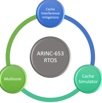
The previous section highlights the importance of mitigating introduced interferences during the transition from a single-core RTOS to a multicore RTOS. One of the main source of interferences is the cache memory. Suppressing or mitigating these interferences requires an algorithm and a way to model these interference in the cache memory. Figure 1.1 gives the overview of our research project.
Figure 1.1 Overview of the research contribution
• Exploration of potential interferences sources
• Investigations on how to mitigate those interferences and study existing mitigation means
• Proposing an approach for interferences mitigation in the cache, using the cache locking technology
The overall contribution of this thesis is to design a framework to mitigate cache interfer-ences occurring in multicore systems, by selecting data to lock in the cache. The specific contributions of this thesis for the framework are:
- A method to trace memory accesses for hardware probes
- The specification and development of a new cache simulator as a module of the frame-work and an implementation of a cache simulator: supports locking, miss/hit per access and more
1.3 Report Organization
The report is organized as follows. Chapter 2 sets the basis used throughout the thesis to facilitate the lecture of the following chapters. Chapter 3 gives the literature review of the scientific and technological background required to accomplish the research. Chapter 4 describes the cache locking framework to mitigate interference caused by local accesses within a core. Chapter 5 describes in more detail the cache simulator developed and used in the cache locking framework. Chapter 6 summarizes the findings and gives key points to be addressed in future research.
CHAPTER 2 BASIC CONCEPTS
In this chapter, we give definitions of the main concepts that will be used throughout the thesis.
2.1 Real Time Operating System
Operating System is an interface between software applications and hardware systems. It manages the system’s resources (memory, Central Processing Unit (CPU) usage and others). It enables applications to run on hardware systems without being aware of these systems’ specifications.
Real-time Aside from functional results, real-time systems have timing constraints to meet. A timing error, such as a deadline miss, can be as wrong as a bad return value. The system reacts to its environment through sensors, actuators and other Inputs/Outputs (IOs).
Real-Time Operating System (RTOS) is an operating system designed for real-time management. RTOSs are used for critical systems for which a given functionality must be done within a given time interval. An RTOS must ensure that the Worst Case Execution Time (WCET) of each task is respected. There are mainly two ways to estimate a WCET: the static estimation and dynamic estimation [10]. There is always a margin added to the estimated WCET for more safety. The more precise the WCET estimation is, the less margin there is, the more tasks can be scheduled and the better the hardware resources are used.
Execution time determinism The determinism of execution time can be measured with its standard deviation. The smaller the standard deviation is, the more deterministic the system execution time is. The determinism is really important for real-time systems, since it can guarantee the timing behavior of a system.
Periodic tasks in RTOS Periodic tasks are defined by two values: its period (the interval between each time the task is to be run) and its deadline (the expected time before the task must be completed).
Sporadic task in RTOS As opposed to a periodic task, the starting time of a sporadic task cannot be predicted. A sporadic task is defined by its deadline.
Hard real-time task A task for which a deadline miss is critical to the system and should never occur.
Soft real-time task A task for which a deadline miss is not critical for the system but may lower the quality of service.
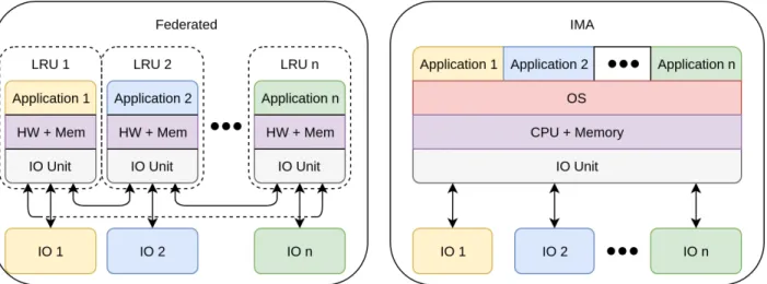
2.2 Federated architecture vs Integrated Modular Avionics (IMA) architecture In the end of the twentieth and the beginning of the twenty-first century, avionics systems underwent the transition from federated architectures to IMA [11]. The main reason was to reduce Size, Weight, and Power (SWaP) issues, which are common to most embedded systems.
Figure 2.1 illustrates the difference between applications implemented with federated archi-tectures and with IMA. In a federated architecture, each application has its own hardware called a Line Replaceable Units. Line Replaceable Units can be seen as a set of interconnected boxes. The drawback of these easily replaceable hardware units is the cost of redundancy of hardware. This is one of the reasons IMA architectures are used today: one computing unit can be used to support multiple applications, allowing a hardware computing unit to be used by multiple applications, therefore the cost of redundancy is reduced.
2.3 Cache memories
Caches are memories located between the CPU and the main memory. The cache plays the role of a temporary memory, enabling faster access to frequently used data. Figure 2.2 gives the high level view of a cache memory-based system. Each time a CPU requests a memory data, first it requests it to the cache then if the data is not present, the cache requests it to the main memory. The number of CPU cycles required to access data located in the cache is smaller than in the case where the data is located in the main memory. This brings an important increase in performance (faster execution and less power consumption) [12].
Figure 2.2 Simplified view of caches in system
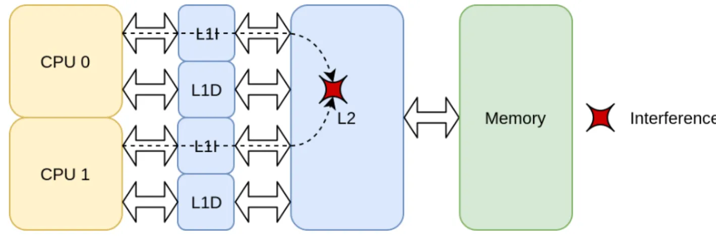
Figure 2.3 illustrates a typical cache architecture in a two-core system. Two (e.g. 16KB) L1 private caches, one for instruction and one for data, and one (e.g. 256KB) L2 shared cache are distributed between the two CPUs. Depending on the access type (instruction or data) and the requesting CPU, the request path will be different throughout the cache levels. For instance, if CPU 0 requests an instruction, first its first private level of instruction cache (L1I) is checked. If the instruction is not there, then L2 is checked. If the instruction cannot be accessed then the main memory is checked.
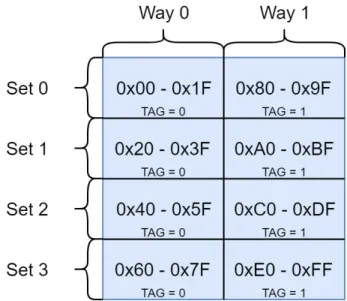
A cache is characterized by multiple parameters. Figure 2.4 illustrates some of the main parameters and some of their possible values: the number of sets (4), the number of ways (2), the size of cache block (32 bytes). The data copied from the memory to the cache is stored in a cache block. Its size is usually expressed in bytes. The cache is typically modelled as a matrix, with the lines being the sets, the column being the ways and a cell being a cache block [13]. In Figure 2.4, the cache block at the set 0 and way 0 contains the data referenced by the addresses 0x0 to 0x1F.
Figure 2.4 4-way set-associative 256B cache 32B block size
Figure 2.5 presents a cache addressing example. In the example, the last 5 bits (Offset) define the byte referenced within the cache block (the total number of bytes in a block is 25 = 32), the previous 2 bits (Set Id) define in which set the block is present (the total number of sets is 22 = 4) and the 25 remaining bits, called the TAG, is used to find the cache block within the ways of a set. If the data is present in the cache, it is called a cache hit, but when it is not, there is a cache miss and a replacement policy is used to select which way of the set to replace with the new data. The TAG is a metadata of a cache line, as shown in Figure 2.4.
Figure 2.5 Indexed address in cache
2.4 Interference in multicore systems
Using multicore architectures brings a lot of performance improvement compared to single-core ones, since they can handle more work in parallel reducing overall workload and execution time [1]. When a system requires to run several applications simultaneously, a single-core has one CPU to divide in time slices, whereas a multicore has several CPU running in parallel which enables a faster execution of the applications. But taking profit of multicore parallelism has its costs. When several cores are trying to access the same resource, only one core can be given the access, which impacts the performance of the other cores. This highlights the fact that one application can have unintended impact on the execution of another one. This phenomenon is called interference.
In [2], several interference channels are discussed when using multicore systems, either soft-ware or hardsoft-ware. The channels that impact the most the execution determinism are those related to the caches [2] [14]. The most important issue with caches is that one application may evict cache lines containing data used by another application. This is illustrated in Fig-ure 2.6, where CPU 0 accesses an instruction not located in the cache, which evicts a cache block from L2 cache containing instructions used by CPU 1, thus impacting its execution time. This is an example of indirect interference.
Another type of interference is the contention on a shared resource. Figure 2.6 also illustrates it using the caches: L2 cache is requested at the same time by CPU 0 and CPU 1. The resource is then allocated to one of the requesters slowing down the execution time of the other one. This is an example of direct interference.
Figure 2.6 Cache-related interference in a dual-core system
Interferences in multicore systems have several drawbacks, one of them being that, depending on the second application running in parallel, the execution time of a given interfered appli-cation is lowered. This brings non-deterministic behavior of the appliappli-cation, which cannot be tolerated in avionics systems where lives depend on the correct execution of the system.
2.5 Partitioned multicore RTOS: ARINC-653
This section introduces 653 [5], a standard for partitioned RTOS. The ARINC-653 standard gives specifications for a partitioned RTOS. According to this standard, the partitioning must be done in space and in time.
Space partitioning Each partition is isolated regarding hardware usage, such as memory space: each partition has a set of addresses in memory and it is the only one having the rights to access them (see Figure 2.7).
Figure 2.7 Memory space partitioning
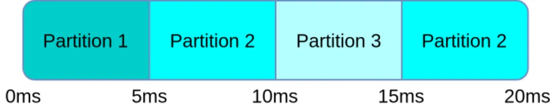
Time partitioning The CPU time is divided in several time windows. Each time window is allocated to a partition. During one of its time windows, a partition is the only one executing on a CPU. All partitions are allocated time windows within a period of time called major time frame, as seen in Figure 2.8. The schedule is then repeated every major time frame.
Figure 2.8 Example of a major time frame illustrating time partitioning
The standard also specifies services that the RTOS must offer. These services are called APEX services.
APEX Application Program Interface (API) The services offered by this API are the ones responsible for creating the ARINC-653 partitions and of the potential communications between them. An ARINC-653 partition is comprised of several ARINC-653 processes that share the partition’s context. An analogy with POSIX’s API would be that ARINC-653 partitions are POSIX processes and ARINC-653 processes are POSIX threads.
Interpartition communication The standard specifies how two partitions may commu-nicate. The communication means are messages using channels or ports. There are two modes of communication:
- Sampling mode — only one message is stored in the source port, it is overwritten each time the source partition writes. It is useful when a partition requires the latest status of a data.
- Queue mode — messages sent are stored in a FIFO order. Each partition (sender and receiver) is responsible in handling the situations when the queue is full or empty.
Intrapartittion communication There are several communication means between the processes of a same partition:
- Blackboard — very similar to sampling mode; instead of being between partitions, it is between ARINC-653 processes.
- Buffers — very similar to queue mode; instead of being between partitions, it is between ARINC-653 processes.
- Semaphore: ARINC 653 semaphores conform with the classical definition:
WAIT_SEMAPHORE is called to wait on a semaphore (if the value of semaphore not equal to zero, the semaphore is decremented and the process continues, or else it is blocked until the semaphore is incremented). SIGNAL_SEMAPHORE is used to increment the semaphore’s value and potentially freeing a locked process. Waiting processes are queued in First In First Out (FIFO) order, and freed one at a time. - Events — processes can wait on custom events, which have two states ("up" if the event
occurred or "down" if not). All processes waiting on an event with a "down" state are blocked until either they timed out or the event’s state changes. When an event is "up" all waiting processes are freed at the same time, making all of them candidates to be scheduled, unlike for semaphores.
- Mutex — as semaphores, ARINC-653 mutexes conform with the classical definition. A mutex can be owned by only one process at a time. Waiting processes are queued in a FIFO, similarly to semaphores.
Health Monitor The Health Monitor is a feature of the RTOS which must handle un-expected error during the execution of partitions, such as deadline misses or arithmetical errors. Through configurations by the user, the Health Monitor then decides what behavior the partition must have, whether it must shutdown or reset the partition, ignore the error or try recovering from it. The ARINC-653 standard requires the RTOS to have a Health Monitor.
2.6 Conclusion
In this chapter, we defined the elements to understand better the contents of this thesis. Besides reviewing these elements, we defined the behavior of caches in the context of a partitioned RTOS and more specifically for critical multicore systems. We defined what interferences are in multicore systems and their impact on the system. The core contribution of this thesis is related to these interferences in multicore systems and the means to mitigate them.
CHAPTER 3 LITERATURE REVIEW
This chapter discusses the works related to the proposed contribution. First, we will present different ARINC-653-compliant RTOSs. The main types of interferences present in multicore systems as well as the existing solutions on how to mitigate them, with an emphasis on cache related interferences mitigation, are also presented. Finally, the related work on cache memory simulations are discussed.
3.1 ARINC-653 RTOSs
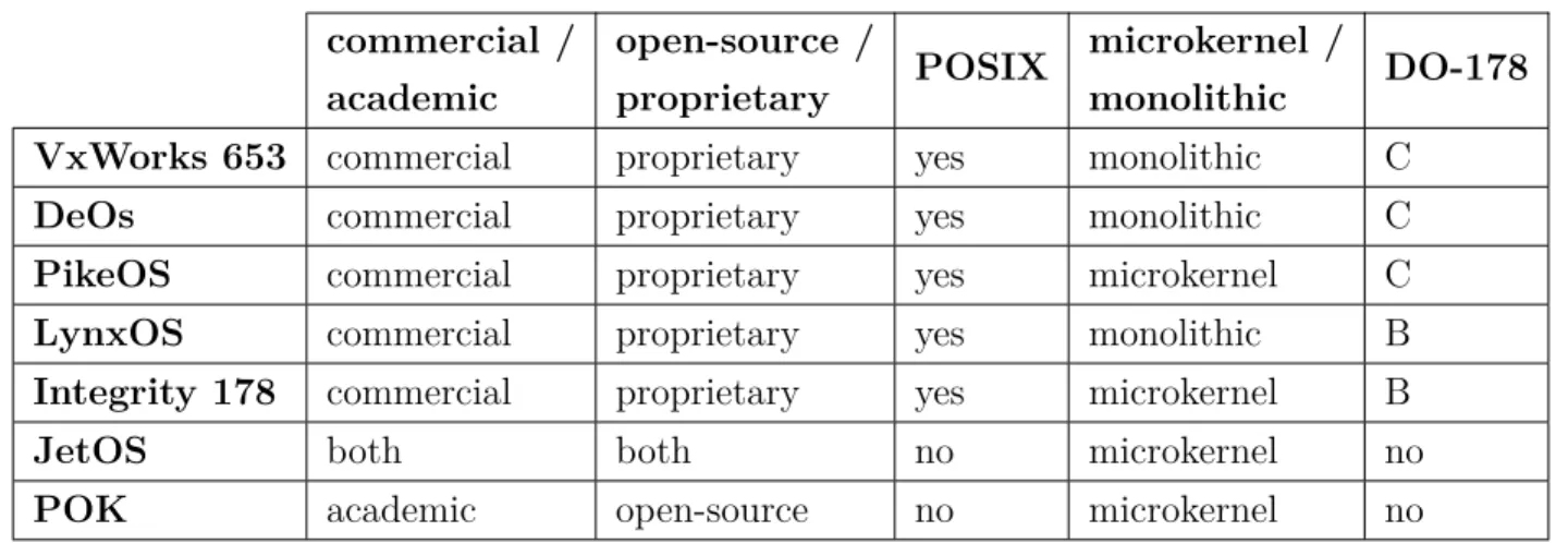
Several RTOSs considering ARINC-653 standard are proposed currently. ARINC-653 compli-ant RTOS are: VxWorks [7], DeOs [15], PikeOS [8], LynxOS [16], Integrity178 [9], JetOS [17] and POK [18].
Table 3.1 gives an overview of these RTOSs according to the following criteria:
• Commercial or academic • Open-source or proprietary
• POSIX interface support, an important factor for the portability of the RTOS • Monolithic kernel or microkernel approach
• The availability of a certification package for DO-178 (A, B or C version)
Table 3.1 ARINC-653 RTOS state of the art commercial / academic open-source / proprietary POSIX microkernel / monolithic DO-178
VxWorks 653 commercial proprietary yes monolithic C
DeOs commercial proprietary yes monolithic C
PikeOS commercial proprietary yes microkernel C
LynxOS commercial proprietary yes monolithic B
Integrity 178 commercial proprietary yes microkernel B
JetOS both both no microkernel no
None of these RTOS offers a set of APIs allowing cache locking. To cope with this inconve-nience, we proposed a set of API for cache locking and we integrated it in the ARINC-653 RTOS provided by our industrial partner Mannarino Systems & Software.
3.2 Interference Overview
Designing multicore software, such as Real-Time Operating System, can be challenging. Interferences are challenges that multicore software developers must take into account, as described in [2]. Interferences can be defined as indirect impacts that an application has on another independent application. In [2] interferences are divided into two categories: (1) hardware interference channels for interferences caused by hardware properties and (2) software interference channels. In [19], the authors highlight the challenges of shared resources in multicore systems, especially concerning isolation in terms of execution time.
3.2.1 Software design considerations
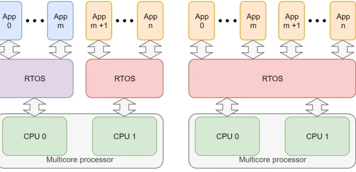
Two types of architectures are currently used for RTOS utilization on multicore systems: Symmetric Multiprocessing (SMP) and Asymmetric Multiprocessing (AMP).
An SMP configuration is a homogeneous multicore design where one Operating System (OS) manages several CPUs.
An AMP configuration is an heterogeneous multicore design and no software can be shared between CPUs.
The difference between AMP and SMP is illustrated in Figure 3.1, where we can see two CPUs running a given number (n) of applications: for the AMP architecture, the first m applications run on CPU 0 and the remaining n-m applications run on CPU1. For SMP the n applications can run on both CPU. As explained in [14], using AMP is an easier way to port from a single-core solution to a multicore one. However this solution does not enable communication between cores. On the other side, SMP enables easier communication and migration of processes between cores. However the need to synchronize all the cores can cause some performance and predictability issues. Some configuration mix those two, such as Time-Variant Unified Multiprocessing (tuMP) [20] where some cores accept only applications bound to that core (a bit like AMP) and other cores that allow application to evolve on multiple cores (a bit like SMP).
We made the choice to work on private caches and with applications restricted to one CPU (an application cannot migrate from one CPU to another), hence our contribution works for
both AMP and SMP configurations.
3.2.2 Memory-related interferences
In [21], the authors highlight interferences caused by memory accesses from different appli-cations running in parallel on different cores. The authors show the impact of the amount of memory accesses made by an application on the determinism of the system.
Several solutions to reduce contention on the memory in multicore systems have been pro-posed recently. In [22], the authors propose a solution to dynamically allocate memory bandwidth to each core. Each partition on a core is allowed a certain amount of execution time and a number of memory accesses. Once these budgets are depleted, the partition is stalled. Additionally, each core has a memory bandwidth, which allows the core to only access the memory in a certain time window. This bandwidth depends on the number of running cores. This solution brings better predictability and improves execution time. In [23], additionally to allocate memory bandwidth budget to each core, a core can reclaim more budget from the remaining bandwidth.
In [24], the authors present their Multi-Resource Server (MRS), which allocates execution time and memory access budgets for each application. This solution reduces interferences of applications for different cores but also within the same core.
In [25], the authors propose a partitioning of Dynamic Random Access Memory (DRAM) banks. The idea is to allocate applications to DRAM banks partitioning, reducing the con-tention on the DRAM since two applications not sharing a DRAM bank will never interfere in the DRAM. The article only focuses on bounding the latency, and not assigning partitions to tasks.
3.2.3 Interconnect/Bus interferences
Most multiprocessor architecture use shared bus and interconnects for communication be-tween the different resources of the system. This can create contention on the bus when different resources are accessed through the bus and thus increase execution time and poten-tially reduce determinism of the system.
The mitigation solutions for bus/interconnect interference presented in the literature concern the scheduling of the requests on the bus. The Multi-Resource Server (MRS) proposed in [24] also contributes to mitigating interference on bus and interconnects.
Figure 3.1 AMP and SMP configuration examples for a dual-core system
based on a Time-division multiple access (TDMA) policy. Although this solution increases the determinism of the system, it will also increase the execution time.
3.2.4 IO-related interferences
The IO-related interferences are similar to all the other interferences. As for the main memory and the bus, IO are subject to contention in multicore systems and arbiters are responsible for allocating the IO to the requesting resources. IO-related interferences can be mitigated by partitioning the accesses to the IOs. In [27], the authors propose to partition access to IOs into time slots. Once the IO partitions are created, they use constraint programming to allocate applications to the partitions.
3.2.5 Cache-related interferences
Interference can occur at cache level. The interference can either be due to contention on the cache (several CPU trying to access the cache at the same time) or be due to one CPU inducing the eviction from the cache of a data used by another CPU.
Cache sharing A cache can either be private to a processor or shared by several CPUs. A typical cache architecture has first level caches private and then the following levels are shared. Contention on shared caches occurs when several lower level caches miss on a request and then the access the next level cache is required (direct interference). Another type of interference in caches occurs when one CPU evicts a cache line used by another CPU (indirect interference). Most mitigation solutions for interferences occurring in shared caches try to limit the amount of cache misses on private caches in order to reduce the number of accesses on shared caches.
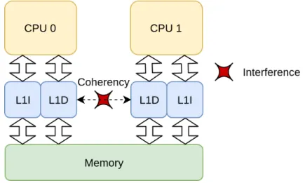
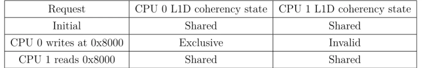
Cache coherency Cache coherency is a necessary mechanism in multicore systems when several processors share data. When multiple processors use the same data, the cache co-herency ensures that the data is correct at all time in all cache. The cache coco-herency process may bring interferences. This creates contention and execution time reduction on private and shared cache. An example of this type of interference is illustrated in Figure 3.2 and Table 3.2. Here we suppose that both CPUs are using the data of physical address 0x8000; when CPU 0 writes at that address, the coherency ensures the invalidation of all the other occurrences at that address, in the other caches. Once CPU 1 wants to read 0x8000, it misses in the cache. Whereas if CPU 0 had not accessed the data before, it would have been a hit. This illustrates the non-determinism that cache coherency can bring to multicore systems.
Table 3.2 Example of cache coherency interference
Request CPU 0 L1D coherency state CPU 1 L1D coherency state
Initial Shared Shared
CPU 0 writes at 0x8000 Exclusive Invalid
CPU 1 reads 0x8000 Shared Shared
Cache replacement policy Since the cache replacement policy is responsible for choosing which line to evict, it is obvious that in certain cases, one replacement policy can imply more cache misses than others. This is not limited to multicore systems, it is also an issue in single-core systems.
3.2.6 Other interference channels
Other interference channels include shared interrupts and other shared resources.
Shared Interrupts In multicore systems, when shared interrupts (ex: IO and peripheral interrupts) occur, they are redirected to a core that must treat them [28]. Execution on this core will then be often interrupted by these shared interruptions, causing its execution time to be reduced. In the case of IO interrupts, the execution time depends on the IO requests of other CPUs. An application can thus impact the execution of another one, highlighting the potential interference channel that is the shared interrupts.
Resource sharing All resources (software or hardware) that are shared between applica-tions are potential interference channels [19]. As shown in the previous paragraphs, proposed solutions are mostly a partitioning of the resource access in time slots, simulating a kind of isolation of access to that resource. Although this solves contention issues on the shared resource, it does not solve the issue of indirect interference.
3.3 Cache-related interference mitigations
The authors in [2] and [14] agree that cache related interferences are one of the most import interferences to tackle with. This is mainly explained by the fact that caches are on a critical route of the system’s execution. Therefore, our research focuses on mitigating these types of interference.
3.3.1 Profiling for cache partitioning
In [29], the authors propose a framework that profiles memory access of a task in order to get the access pattern of the task. Once the pattern is obtained, an offline algorithm is responsible for computing the memory mapping of virtual addresses to perform cache coloring. Additionally, the algorithm selects cache lines to lock for better predictability. This differs from our contribution by locking only the last level cache.
3.3.2 Cache replacement policy selection
In [30], a runtime mitigation of interferences on the cache is proposed. An additional hardware is added to the system which monitors accesses to each way of the cache. A partitioning algorithm then computes, with the information gathered by the added hardware, the way-based cache partitioning for the system’s application. The cache replacement policy is also modified to take into account the computed partitions.
3.3.3 Cache Locking
As the name suggests, the cache locking technique is used to lock in the cache the data that are not subject to eviction. This way, if the data is requested, it will always hit in the cache. The challenge employing this technique is to properly select the data to lock as well as when to lock this data [31]. To lock the cache, one can rely on two different approaches: static locking [32] or dynamic locking [33]. The static technique locks all the data in the cache before the system starts to execute. With this technique, the locked contents of the cache cannot be changed while the system is running. Dynamic locking works during system execution. It employs different algorithms to choose which lines to lock and unlock during execution time, relying on a different set of criteria.
It is possible to have different types of cache data to be explored: processor instruction or data, in kernel or user spaces.
A variety of approaches is employed when selecting the type of data to be locked. Some contributions selected to fully lock [34], which renders cache deterministic because either a datum is locked and each request to it hits in the cache or it is not locked and each request is a miss. To cope with this limitation, most works practice the partial cache locking [35], where the cache is not fully locked or not locked at all.
To select the contents to lock in the cache, one can statically analyze the application [36] or dynamically analyze the application [37]. The static analysis is done by analyzing the
application code without running it. Dynamic analysis is done by profiling the application and select data to lock in the cache based on the information gather during the application’s execution.
Table 3.3 lists existing work on cache locking selection and compares them based on the criteria described above.
Comparing with the above mentioned works, our contribution is a pseudo-static partial lock-ing of both instruction and data of both user and kernel spaces. It takes cache misses and hits into account using dynamic analysis and a cache simulator.
3.4 Trace-Based Cache Simulators
An efficient approach for probing a hardware execution of a system, in order to analyze the interferences in the cache, is to use a cache simulator. Cache simulators can be used to gather information on the behavior of a cache. Such an information is the number of misses per cache level, which gives a hint on the contention in the cache. Plenty of cache simulators are already proposed in the literature, but most of them are for educational purpose and/or only support simple cache replacement policies (such as FIFO, Least Recently Used (LRU) or Random) [44]. A generic cache simulator that can be configured to simulate all types of cache architecture is required to explore the cache-level interference mitigation solutions. Moreover, since we want to simulate the cache locking, we require specifically a simulator that models this technique. The remaining of this section introduces the main cache simulators based on memory access traces and offering some genericty of the simulated cache model.
SMPCache Described in [45], the cache simulator SMPCache is a graphical educational trace-based cache simulator. We can execute the traces step by step and see the evolution of the cache characteristics such as what data is loaded and whether the access was a cache miss or hit. Unfortunately, SMPCache does not support cache locking, but only instruction fetch, data read and write. The traces used for SMPCache holds three information in an ASCII file: the requesting processor, the access type (instruction fetch, data read or data write) and the accessed address. One can configure the cache (replacement policy, cache coherency protocol, etc.). The simulator was designed to be used graphically and it was developed for Windows.
Dinero IV Dinero IV [46] is a uniprocessor cache simulator. The simulator allows the user to configure the cache architecture to be simulated according to a set of parameters: cache levels, cache size, block size, replacement policy, associativity. The obtained simulation
Table 3.3 Review of works on cache locking selection (oldest to most recent) [38] [33] [32] [39] [40] [36] [41] [42] [43] [35] [34] [37] Contribution Static (S) / Dynamic (D) Locking S D S D S S S D D S/D D D pseudo-S Data (D) /
Instruction (I) I D I I I I I D I I I D/I D/I
Kernel (K) /
User (U) locking U U U K U U U U U U U U U/K
Partial (P) / Full (F) locking P P P P F P P P P P F P P Static (S) / Dynamic (D) analysis S S D X S S D D D S/D S D D Cache hits considered for selection X X X X X X X X X
results consist of the amount of cache hit/miss per cache and per access type (instruction or data). In addition to instruction fetches, the number of data reads and miss, Dinero simulates cache invalidation instructions.
None of the above presented simulators take into account the cache locking approach. This is a key feature for the exploration of cache locking algorithm. In order to enable this exploration, we propose a new simulator.
Table 3.4 gives an overview of the main requirements for a cache simulator to be used for interference mitigation solutions exploration. We also position our contribution according to these required features.
Table 3.4 Required features
Dinero Our cache simulator SMPCache Cache architecture configuration
(cache levels, size, etc.) Step by step simulation
Use as a library X
Memory footprint optimization
(binary trace file) X
Acceptable execution time
(< 1 min / 100k accesses) X
Custom replacement policy X
Cache locking simulation X X
3.5 Conclusion
In this chapter, we reviewed the challenges related to the usage of multicore processors in avionic systems. Further, we listed the mitigation means used to address these challenges. The literature review highlighted the impact that cache interferences can have on systems, a fact that lead us to focus on cache-related interferences in this work. This work focuses on cache locking as a way to mitigate cache interference, as this approach seems promising to reduce contention on shared caches.
We presented the state of the art for cache locking approaches and for the simulation solutions for cache memories. None of the presented cache lock content selection algorithms take into account all the key aspects related to this process (list from Table 3.3).
The current simulators do not allow to consider the cache locking mechanism while being generic in order to support several architectures.
CHAPTER 4 CACHE LOCKING FRAMEWORK
This chapter presents the proposed modular framework for cache locking. After the problem formulation and an overview of the proposed solution, we will present the main modules of the framework.
4.1 Problem Formulation
This section formulates the problem solved by the proposed framework. First we formulate the inputs and the outputs, then we give the relation between them.
4.1.1 Framework Input
The framework’s sets of inputs are : the first set concerns the cache architecture while the second set is related to the applications for which the cache locking selections must be done. The cache related inputs are:
• Cache configurations: the configuration is defined by the cache index and its own con-figuration given by its size, the number of ways, the number of sets and the replacement policy. The cache configuration is defined in the expression (4.1) and will be described in more details in section 5.3.
CacheConf = {(cacheId, conf ) | cacheId ∈ [[0, N − 1]]}, (4.1) where N is the number of caches, cacheId is a cache index and conf the configuration of the cache refered by cacheId.
• CPU cache entry points: each CPU has two entry points to the cache (one for instruc-tions and one for data). CoreCacheMap represents the correspondence of the caches with their entry points. CoreCacheMap is defined in the expression (4.2).
CoreCacheM ap = {(cpuId, (cacheinst, cachedata)) | cpuId ∈ [[0, M − 1]]}, (4.2)
where M is the number of CPUs, cacheinst (resp. cachedata) represent the index of the
instruction entry point (resp. the data entry point) for the CPU of index cpuId. • Cache levels relationship: each cache is related to a lower level cache, except for the last
level caches for which the next level is the main memory. This relationshiip is defined in the expression (4.3).
N extLvlCacheM ap = {(cacheId, nextCacheId) | cacheId ∈ [[0, N − 1]]}, (4.3) where N is the number of caches and nextCacheId is the index of the next level cache of the cache with the index cacheId.
The applications’ related inputs are:
• The binary of the RTOS and of the applications. We will use the notation Binary for this type of inputs.
• The ARINC-653 schedule of the partitions:
Schedule = array((of f set, partitionId)) (4.4) a sorted array representing the time windows in the major time frame where of f set is the offset in the major time frame of the partition of index partititonId.
The input set of the defined framework is defined by the expression (4.5).
input = (CacheConf, CoreCacheM ap, N extLvlCacheM ap, Binary, Schedule) (4.5)
4.1.2 Framework Outputs
The framework’s output is given by a set of addresses to lock in each cache and for each application. The output is defined in the expression (4.6).
output = {(partitionId, cacheId, addressList) |
partitionId ∈ [[0, K − 1]] and cacheId ∈ [[0, N − 1]]}
(4.6)
where addressList is a list of addresses to lock in the cache of index cacheId for the partition of index partitionId, N is the number of caches and K is the number of partitions.
It is to be noted that the selected lines to lock are specific to the applications and the RTOS given as inputs and they are obtained considering the execution determinism of the applications in the system.
4.1.3 Inputs and Outputs Relationship
Figure 4.1 shows the inputs and the output of the cache locking selection framework. The binary of the operating system and applications is fed to the framework as well as some configurations for the framework. After execution of the cache lock selection algorithm, the lines to lock in the cache are then outputted
Figure 4.1 Cache locking framework IOs
The framework gives the tools to implement a function f defined as follows: output = f (CacheConf, CoreCacheM ap,
N extLvlCacheM ap, Binary, Schedule)
(4.7)
4.2 Cache Locking Overview
The overview of the proposed framework is given in Figure 4.2. It is worth noting that the targeted system architecture must support locking and that the RTOS used supplies a locking API.
The framework is divided in three main modules: the memory access tracer, the cache simulator and the cache locking algorithm. Each module can be replaced by another version, as long as the inputs/outputs are respected.
Memory access tracer The first module is responsible for gathering the memory access traces from the execution of the system and store them in an exploitable format for the framework.
Cache Simulator The second module is responsible for a step-by-step simulation of the behavior of the cache when executing memory access traces provided by the first module.
Cache locking algorithm The third module is responsible for selecting the addresses of data to lock in the cache, using the results obtained with the cache simulator.
Figure 4.2 Cache locking framework overview
4.3 Memory access tracer
The role of the memory access tracer is to gather traces from the execution of applications on an RTOS, all the execution traces. The memory tracer is also in charge of storing traces in a usable format for the cache simulator and the cache locking algorithm. The tracer is based on a well-defined trace structure that we proposed. This structure will be described in section 4.3.1.
We propose two approaches for the tracer implementation: (1) a QEMU-based approached described in section 4.3.2 and (2) a hardware probe approach described in section 4.3.3. The memory access tracer’s function f is defined in the expression (4.8).
f : Binary 7→ T races (4.8)
where Traces are the memory access traces for a set of time windows:
T races = {T imeW indowId, W indowT races} (4.9)
where WindowTraces is a sorted array of the memory access traces of the time window of index TimeWindowId.
W indowT races = array(M emAccess) (4.10) where MemAccess is a memory access trace defined in Section 4.3.1
4.3.1 Trace structure
Each access trace must contain enough information in order for the cache simulator to be able to correctly simulate the cache. In order to optimize memory footprints of the traces, we chose to save the traces in a binary format: we need 20 bytes per trace when using 64 bit addresses and 16 bytes per trace when using 32 bit addresses. Figure 4.3 shows the binary representation of each trace. Figure 4.4 gives a more detailed description of the trace flags. Finally, Table 4.1 gives more details on each field of a trace.
Figure 4.3 Trace binary format for 64 bit and 32 bit addresses
Table 4.1 Trace fields description. The numbers in parenthesis give the values of the field.
Field Description
Address The requested address
Timestamp The timestamp (to be able to order the memory accesses) Core ID The id of the core making the request
R/W Read access (0) or Write access (1)
D/I Requested data type: Data (0) or Instruction (1) K/U Protection level: Kernel (0) or User (1)
Access type Memory Access (0), Flush (1), Invalidate (2), Flush/inval (3), Lock (4) Unlock (5), Prefetch (6), DCBZ (7)
Access granularity Line (0), Set (1), Way (2), Cache (3)
Coherency Cache coherency is required (1) or not (0) for the request Cache level Concerned level if required: L1 (0), L2 (1), LLC (2), all (3)
Inhibit The cache is inhibited (1) or not (0) for the request Write Through Whether the access is write through (1) or not (0)
Exclusive If 1, the prefetched data is exclusive in the cache Unused Remaining bits for future improvements
In our approach, the traces were collected using (1) the Quick Emulator (QEMU) which emulates the execution of the system or (2) using a hardware probe to have the traces from a real execution.
4.3.2 QEMU
QEMU is the most industrially used open-source system emulator that supports a broad range of architectures [47]. An emulator behaves as the system behaves but does not represent how the system achieves this behavior.
In order to collect the traces, we had to instrument QEMU. This instrumentation enabled us to create the traces and activate/deactivate the tracing when required.
Obtaining traces In order to create the traces, each time an instruction is emulated within QEMU, we check if it’s an instruction required to trace, then we create a trace respecting the format given in section 4.3.1.
Activating/deactivating tracing After collecting the traces from QEMU, we need to activate or deactivate the tracing using two instructions: one for the activation and one for the deactivation. We propose a solution that takes advantage of the instructions that are not used in the emulated architectures. In the case of PowerPC e500 processor, 0xFFFFFFF1 and 0xFFFFFFF0 are two unused instructions. An example on how to trace a portion of code is shown in Listing 4.1.
1 __asm__ __volatile__ (" . l o n g 0xFFFFFFF0 ") ; 2 \\ Code t o t r a c e
3 __asm__ __volatile__ (" . l o n g 0xFFFFFFF1 ") ;
Listing 4.1 PowerPC e500 QEMU tracing example
Discussion Exploiting QEMU for tracing brings the advantage of flexibility and facility to trace memory accesses for new architectures. However the emulation time is slow compared with the hardware execution. Moreover, the timing behavior, one of the main dimensions of the ARINC 653 RTOS, may not be considered.
4.3.3 Hardware probe
A hardware probe is a system capable of gathering information on the system while it executes without modifying the system’s behavior. It is very important to use non-intrusive hardware probes. The probe we used is the LA-7630 NEXUS Debug/Trace probe from Lauterbach.
Obtaining traces In order to obtain traces using hardware probe, a specific software is required. In our case, we obtained traces using the NEXUS probe required to use the Trace32 software. The software can be used to trace a given section of a program (defined by two points in the program). The traces are exported in a binary. A translation of this binary to a binary compatible with our framework was required and thus developed.
Activating/deactivating tracing The debugging software allowed us to set the beginning and the end of tracing in the program, which made the tracing easier.
Discussion Our challenge regarding the hardware probing is that the debugging software traces only the virtual addresses and not the physical addresses. In order to cope with this issue, we implemented an address translator. This stage was facilitated by the fact that the traces of an execution relate only to one partition and the translation from the virtual to physical address is static.
4.4 Cache locking selection algorithm
In this section, we describe the cache locking algorithm and its interaction with the cache simulator. First, we give the objective of the algorithm. Then we present two approaches we used for the cache locking: (1) an approach based on the Greedy algorithm and (2) an approach based on the Genetic algorithm.
4.4.1 Objective
The objective of the cache locking selection algorithm is to find for each cache memory unit and each partition the best set of data addresses to lock in the cache. The problem is divided to give a result for each partition.
Since the cache simulator gives the behavior of the cache when running traces with some given initial configurations, the cache locking algorithm can take profit of it. Using the number of misses and hits for each request address that occurred in the cache, the algorithm computes the best set of lines to be locked.
4.4.2 Comparing locking configurations
In order to select the best locking configuration, we must be able to compare locking config-urations.
In order to do so, the user can specify for each cache the latency of a hit as well the latency of a miss. When running the cache simulator, we can can obtain the information on the number of misses and hits per address and per cache (4.11. Therefore, we can have a cost per address (4.12), a cost per set of a cache (4.13), a cost per cache (4.14) and a total cost for a configuration (4.15):
CostAdd,Ci = hitsAdd,Ci × hitLatencyCi + missesAdd,Ci× missLatencyCi (4.11)
CostAdd=
X
Ci
(CostAdd,Ci) (4.12)
CostSeti,Cj =
X Add∈Seti,Cj (CostAdd,Cj) (4.13) CostCi = X Setj,Ci
(CostSetj,Ci) (4.14)
T otalCost =X
Ci
where
- Ci is the cache of index i
- Seti,Cj is the set of addresses of i
the set of cache C j
- hitLatencyCi (resp. missLatencyCi) is the latency to manage a cache miss (resp. a
cache hit) in the cache Ci
- CostAdd,Ci is the cost induced by the hits and misses of address Add in the cache Ci
- CostAdd is the cost induced by the hits and misses of address Add
- CostSeti,Cj is the cost induced by the hits and misses in Seti,Cj
- T otalCost is the total cost of a cache configuration for a certain trace
4.4.3 Greedy Algorithm
We defined the Greedy algorithm to solve the problem of cache locking for each cache, starting by the first level caches. A locking configuration on a cache will impact the requests on its next level cache.
Intuitively, the Greedy algorithm definition would aim to lock the addresses with the most number of misses. Although this will increase determinism, this will most likely also increase the execution time. Indeed, each access to the cache hits if the requested address is locked, otherwise it misses. Unless all the requested addresses fit in the cache, in which case locking is not useful, locking the whole cache is not the best solution.
The defined Greedy algorithm explores different configurations and selects the best one. In order to deal with the complexity, we apply the parallelism and the divide for conquer principle.
Figure 4.5 shows the execution flow of the Greedy algorithm. We solve the problem per cache level, from the first level. For each level, we solve the problem per cache. We can also divide the problem per cache set. As seen in Section 2.3, the cache is divided in sets and the address space is divided by these number of sets. Thus, a locking configuration for one set will only impact addresses of this set. We then try to lock one way, two ways, etc. up to the number of ways in the cache with the addresses with the smallest cost CostAdd,Ci (4.11) and
run these configurations with the cache simulator. Once we have the results, we can then select the best cache locking selection per set, with the smallest CostSeti,Cj (4.13) and go to
4.4.4 Genetic Algorithm
With the ability to give to the simulator the addresses of data to initially lock in the cache, the Genetic algorithm can test a configuration and see whether it’s a better fit or not than previously tested configurations.
Figure 4.6 shows the execution flow of the Genetic algorithm. The first step of the algorithm is to generate an initial population. A population is a set of individuals each representing here a locking configuration.
A new population is then generated from this initial population. There are several steps to have a new generation of the population. First, we choose whether or not we apply crossover on the previous generation population (generate one individual from two individuals). Then we randomly apply mutation on individuals (in our case, change some addresses in a locking configuration). Some new generated individuals can be injected to have "fresh blood". Once we have all these new individuals we select the best ones in order to always have the same number of individuals from one generation to another. The selection is based on the fitness or cost of the individuals and is computed with the equation (4.15).
We repeat the process of generation until either the imposed number of generations is attained or the stagnation of the best configuration. The best configuration of the last generation is the one selected as output of the algorithm.
4.5 User flow for the cache locking framework
Figure 4.7 gives the flow diagram for the utilization of the cache locking framework, in order to gather cache locking configurations for a specified set of applications.
The first step is to trace the memory accesses from the execution of the applications using either QEMU or a hardware probe. Next, if required, the traces must be translated in a binary format defined in Figure 4.3. The user must then specify the configurations of the target system’s cache architecture. Once the user selects the cache locking algorithm (Greedy or Genetic), he collects the selected addresses to lock in the cache and can then run the applications on the target system using the acquired cache locking configurations.
4.6 Implementation for performance improvements
Since our framework is trace-based and can require to rerun several times the traces, the execution time can be long without some optimization measures we proposed. Two solu-tions in order to improve the execution are: (1) the optimization of trace sizes and (2) the parallelization of some algorithms. We will detail both of these measures in this section.
4.6.1 Trace and data structure optimization
There are two main advantages to optimize the traces. The first one is the reduction of the memory footprint for a trace and the second is the reduction of the time to read the data from the trace (i.e. by doing a memcpy).
We chose to store traces in binary format instead of ASCII format (requiring one character for one byte). This was easy to implement since we mainly manipulate numbers and bits (for flags). The size of an access trace is of 16 bytes for 32 bits addresses and 20 bytes for 64-bit addresses.
We also minimized the number of copies of variables and we used the references/pointers of variables/objects in functions.
In order to reduce the time spent to construct an instance of a cache simulator, each time a cache simulation is launched, the cache simulator is restarted with some new configurations but with the same cache architecture and specifications.
4.6.2 Algorithm Parallelization
The cache simulator must execute step by step the traces and the state of the caches evolves sequentially, thus the simulation of caches for one trace cannot be parallelized. The mitigation algorithm is completely user-dependent and can contain any type of parallelization.
In the case of our cache locking selection algorithm we applied parallelization at several levels. In the Greedy version, we could launch several instances of the cache simulator: one locking one way of the cache, another one locking two ways, etc. This considerably reduces the execution time of the algorithm (up to 97% according to our experiments).
4.7 Results
In this section we will discuss results obtained when using the cache locking framework. These results rely on the cache simulator discussed in Chapter 5.
4.7.1 Experimental Setup
Table 4.2 gives an overview of the testbenches used in our experiments. The testbenches are from MiBench [48] (dijkstra, fft, adpcm) and SNU-RT [49] (jfdctint, matmult) benchmarks. The selected testbenches are memory intensive, hence use the cache oftenly. We configured the tests in order to have a large number of accesses to the cache.
We ran a set of testbenches on an ARINC-653 proprietary RTOS supporting cache locking provided by our industrial partner Mannarino Systems & Software. The software stack was executed on a MPC5777c Power Architecture, using only one of the available e200z7 CPUs. We used the Lauterbach debugging probe with NEXUS trace collector.
Table 4.2 Description of used testbenches Testbench Description
ADPCM Pulse Code Modulation for analogic to digital conversion
Dijkstra Dijistra algorithm to find shortest path between nodes in a graph MatMult Basic matrix multiplications
FFT Fast Fourrier Transform
JFDCTint JPEG integer implementation of forward Discrete Cosine Transform
![Table 3.3 Review of works on cache locking selection (oldest to most recent) [38] [33] [32] [39] [40] [36] [41] [42] [43] [35] [34] [37] Contribution Static (S) / Dynamic (D) Locking S D S D S S S D D S/D D D pseudo-S Data (D) /](https://thumb-eu.123doks.com/thumbv2/123doknet/2336327.32764/34.918.109.816.153.442/table-review-locking-selection-contribution-static-dynamic-locking.webp)
