INNOVATIVE VASCULAR PROSTHESES COMBINING 3D ELECTROSPUN NANOFIBER MATRICES AND BIOACTIVE COATINGS PREPARED BY PLASMA-POLYMERIZATION
HOUMAN SAVOJI
INSTITUT DE GÉNIE BIOMÉDICAL ÉCOLE POLYTECHNIQUE DE MONTRÉAL
THÈSE PRÉSENTÉE EN VUE DE L’OBTENTION DU DIPLÔME DE PHILOSOPHIAE DOCTOR
(GÉNIE BIOMÉDICAL) DÉCEMBRE 2016
UNIVERSITÉ DE MONTRÉAL
ÉCOLE POLYTECHNIQUE DE MONTRÉAL
Cette thèse intitulée :
INNOVATIVE VASCULAR PROSTHESES COMBINING 3D ELECTROSPUN NANOFIBER MATRICES AND BIOACTIVE COATINGS PREPARED BY PLASMA-POLYMERIZATION
présentée par : SAVOJI Houman
en vue de l’obtention du diplôme de : Philosophiae Doctor a été dûment acceptée par le jury d’examen constitué de : M. JOLICOEUR Mario, Ph. D., président
M. WERTHEIMER Michael R., D.Sc.A, membre et directeur de recherche Mme LEROUGE Sophie, Ph. D., membre et codirectrice de recherche M. AJJI Abdellah, Ph. D., membre et codirecteur de recherche
M. THÉRASSE Éric, MD, membre
DEDICATION
ACKNOWLEDGEMENTS
First and foremost, I am deeply grateful to all my PhD supervisors: Prof. Michael R. Wertheimer, Prof. Sophie Lerouge and Prof. Abdellah Ajji for their continuous mentoring, inspirational guidance, encouragement, exceptional support, motivation, and providing resources in their laboratories during my PhD studies.
My kind and sincere gratitude to Prof. Wertheimer; a distinguished professor in his field, who has always been a supportive mentor for me. He has always generously been there for me whenever I needed support in the course of this research. I am honored to be his student these past few years. I have been learning from him not only through my scientific journey but also in my life. His attitude in thinking about science and technology and solving research and technical problems always inspires me as a young researcher.
My deep gratitude to Prof. Lerouge, a successful hard working and passionate researcher, for her invaluable advice, excellent guidance, continuous supports and constantly challenging me to be a better researcher. Without her great supervision and advice, I wouldn’t have completed this thesis. I learned a lot from her not only in my research but also in my career path. Her broad knowledge in biomaterial and tissue engineering fields are invaluable to the success of my PhD research project and will definitely help me significantly in my future careers.
My great gratitude to Prof. Ajji, an outstanding advisor, who always encouraged and guided me during this research. His insightful suggestions, constant support and patience enabled me to complete this multidisciplinary research. This work would not have been possible without his invaluable technical and moral support.
I would like to express my gratitude to Dr. Gregory De Crescenzo for giving me the opportunity to work in his laboratory to complete the last part of this research.
I am grateful for my thesis committee members: Prof. Mario Jolicoeur, Prof. Gaétan Laroche, Prof. Éric Thérasse, for their time to read this thesis and their invaluable suggestions.
I would like to sincerely thank Dr. Marion Maire, Dr. Afra Hadjizadeh, Dr. Pauline Lequoy, Dr. Benoit Liberelle, Dr. Caroline Ceccaldi, Dr. Bachir Saoudi, Mr. Matthieu Gauthier, Mme. Suzie Poulin and Dr. Josianne Lefebvre, Mrs. Clair Cerclé, Mrs. Nicole MacDonald, Mr. Yves Leblanc for their valuable assistance, technical support and insightful suggestions during the course of this
research, to Dr. Bernard Nisol for the French translation of the Abstract, to Dr. Amir Sheikhi for the proofreading and Mr. Nicholas Laugher for the editing of the Chapters 1, 2, and 7.
I am also indebted to my amazing colleagues and friends at the Institute of Biomedical Engineering, Chemical Engineering Department and Engineering Physics Department at Ecole Polytechique Montreal, and Laboratory of Endovascular Biomaterials (LBeV), Hospital Research Center of University of Montreal (CRCHUM), and McGill University, who accompanied me along this journey, offering me practical supports and warm friendships. Many thanks to Gaël, Pradeep, Elias, Marouan, Ahmed, Angel, Juan-Carlos, Hicham, Amélie, Sepideh, Fatemeh, Yasaman, Francesco, Saoussen, Cindy, Mélusine, Jessica, Eve, Atma, Audrey, Sara, Ali, Abeer, Amin, Mandana, Ali, Alireza, Hossein, Frederic, Samantha, Charles, Vincent and many more whose names I might have forgotten to mention.
Last but not the least, I would like to give my special thanks to my beloved parents, Hourinaz Abbasi Rashti and Mohammadreza Savoji, and my supportive and kind brother, Hamed for their unconditional love and supports from overseas.
RÉSUMÉ
Malgré des efforts indéniables, l’élaboration de prothèses vasculaires (VGs) de petit diamètre (6 mm) pour le remplacement de vaisseaux occlus ou la déviation du flux sanguin (bypass) se heurte encore à des résultats mitigés. Parmi les principaux requis d’un greffon vasculaire synthétique de petit diamètre (SDVG) et pour l'ingénierie tissulaire de vaisseaux sanguins, citons l’hémocompatibilité et la compliance mécanique. En particulier, il est essentiel d’assurer la formation d’une monocouche continue de cellules endothéliales (ECs) à l’intérieur de la lumière, qui résiste aux contraintes de cisaillement physiologiques. Pour ce faire, une approche classique consiste à ensemencer la lumière du greffon avec des ECs, antérieurement à l’intervention. Néanmoins, une faible rétention des cellules sous flux sanguin, et la morphologie des textiles conventionnels constituent des freins à la formation de la monocouche. Les matériaux électrofilés permettent d’améliorer la conformité du greffon, et reproduisent plus fidèlement la morphologie de la matrice extracellulaire des vaisseaux sanguins ; ils présentent cependant le même problème de rétention et croissance des ECs. Dans cette recherche, il a été démontré qu’un tapis de nanofibres de PET électrofilées (ePET), organisées de façon aléatoire, et subséquemment recouvert d’une couche mince de polymère-plasma riche en amines primaires (L-PPE:N) permet un contrôle relativement fin des propriétés structurelles et de surface, nécessaires la formation de monocouches d’ECs confluentes sur VGs. En effet, il a été démontré que ces dépôts L-PPE:N augmentent significativement l’adhésion et la croissance d’ECs, même sous contrainte d'écoulement induite par cisaillement. La rétention cellulaire se voit aussi améliorée, mais n’est cependant pas encore idéale. En outre, les couches L-PPE:N sont également thrombogènes. Pour pallier à cela, il a été proposé de greffer du sulfate de chondroïtine (CS) sur les couches L-PPE:N; le CS est connu pour empêcher l’adhérence de plaquettes ainsi que pour favoriser l’adhésion et croissance de cellules endothéliales de la veine ombilicale humaine (HUVECs). Le greffage de CS sur L-PPE:N, lui-même déposé sur tapis électrofilés a effectivement montré une forte augmentation de la colonisation en HUVEC, et une amélioration de leur rétention (résistance au détachement).
De plus, l’alignement des ECs dans la direction du flux sanguin est connu pour renforcer la rétention des cellules dans les artères. L’approche classique pour obtenir artificiellement une monocouche de cellules alignées implique un pré-conditionnement long et coûteux de l’implant dans un bioréacteur (in vitro), sous flux. Ici, nous avons testé et comparé des tapis de PET
obtenus à la fois par électrofilage aléatoire et aligné : nous avons pu observer une légère augmentation de la résistance des ECs à la contrainte de cisaillement dans le cas des fibres alignées.
Nous avons également évalué et optimisé le potentiel de ces structures électrofilées pour la media des vaisseaux naturels, qui est constituée de cellules musculaires lisses vasculaires (VSMCs) et de fibres de collagène alignées circonférentiellement, essentielles à la contraction, à la dilatation et au contrôle de la pression sanguine. Nous avons ainsi fabriqué des structures de ePET aligné et avons cherché à optimiser leur compliance à l’aide de trois différentes approches d’érosion (chimique) par plasma, dans le but d’approcher au mieux les propriétés mécaniques et surfaciques des vaisseaux sanguins naturels : (i) décharges corona dans l’air, à pression atmosphérique (HP ); (ii) plasma radio-fréquencé à basse pression (LP) et (iii) plasma micro-ondes, (ii) et (iii) étant utilisés soit avec de l’oxygène (O2), pur ou mélangé avec Ar, ou encore
avec CF4. L’approche (iii) a notamment permis une réduction significative du module de Young
après à peine 5 min. de traitement avec O2, sans endommager les fibres. De plus, les changements
observés dans la composition de surface et l’amélioration drastique de la mouillabilité/capillarité en découlant ont mené à une adhésion et une croissance accrues de cellules musculaires lisses (SMCs).
Finalement, les tapis alignés ont été modifiées avec des couches bioactives, basées sur les dépôts L-PPE:N décorés de CS, ce dernier servant de plus de site d’ancrage du facteur de croissance épidermique (EGF). Nous avons pu observer que ces couches (CS-EGF) promeuvent fortement l’adhésion, la croissance et la survie des VSCMs. Ceci suggère que le dépôt de couches bioactives sur tapis électrofilés constitue un excellent moyen de produire des échafaudages pour les parties luminale et médiane des SDVGs, offrant un contrôle fin sur les propriétés structurelles, mécaniques, surfaciques et biologiques nécessaires à une endothélialisation complète et stable de l’implant.
Mot clés : prothèse vasculaire; électrofilage; nanofibres; poly(ethylene terephthalate); polymérisation plasma; érosion par plasma; revêtements bioactifs; morphologie; propriétés mécaniques; chimie de surface; endothélialisation.
ABSTRACT
There have been considerable efforts in developing prosthetic small-diameter (below 6mm) vascular grafts (VGs) as an alternative to autologous grafts to bypass or replace occluded blood vessels. Primary requirements for functional synthetic small-diameter vascular grafts (SDVGs) or tissue engineered blood vessels are hemocompatibility and favorable compliance. Particularly critical is the formation of a continuous, stable monolayer of endothelial cells (ECs) on the lumen under physiological shear stress. To that purpose, seeding autologous ECs on the lumen side of the graft prior to implantation is commonly done. But its success is limited by low cell retention under flow and by the large pore size of conventional textiles that do not favor the formation of a continuous monolayer. Electrospinning enables one to enhance graft compliance and to mimic the morphology of the extracellular matrix of blood vessels, but EC growth and retention on electrospun mats still remain a problem. In this research, it was shown that random electrospun PET (ePET) nanofiber mat coated by primary-amine rich plasma polymer coating (L-PPE:N) lead to finely controlled structural and surface properties that are required for a confluent EC monolayer on VGs. EC adhesion, -growth, and -retention under shear-induced flow stress were shown to be increased by L-PPE:N coating. However, cell retention is still not ideal. Moreover, this underlying L-PPE:N substrate is thrombogenic. To tackle this problem, chondroitin sulfate (CS) was grafted on LP which is known to prevent platelet adhesion while promoting human umbilical vein endothelial cell (HUVEC) adhesion and growth. It was observed that grafting CS on L-PPE:N coated electrospun mats could significantly enhance HUVEC adhesion, growth and their resistance to detachment.
In addition, EC alignment in the direction of blood flow in the natural arteries is known to increase the cell capability to resist detachment under shear stress. This is typically achieved by a long and resource-consuming method involving in vitro fluid flow preconditioning in a bioreactor prior to implantation. Random and aligned electrospun PET mats were fabricated as scaffolds for the luminal layer. It was observed that EC resistance to shear stress was slightly further improved when it was directed by tuning electrospun alignment.
On the other hand, the media layer of native vessels contains vascular smooth muscle cells (VSMCs) and circumferentially-aligned collagen fibres, which are essential for contraction, dilation and blood pressure control. In this research, aligned ePET mats were fabricated as
scaffolds for the media layer, and three different plasma etching techniques were used to bring their mechanical and surface properties in line with those of natural blood vessels: (i) atmospheric pressure (“HP”) corona discharge in air; (ii) low-pressure radio-frequency plasma (“LP”) and (iii) microwave plasma asher, (ii) and (iii) in pure oxygen (O2), or O2 mixture with Ar
or CF4. (iii) gave substantial reduction in Young's modulus after as little as 5 min. treatment in
O2, without damage to the fibers. Changes in surface composition and drastic improvement in
wettability/wicking were also observed, which resulted in promoting adhesion and growth of smooth muscle cells (SMCs). The aligned mats were then grafted with bioactive coatings, based on L-PPE:N coating, CS with tethered epidermal growth factor (EGF). It was found that a CS-EGF coating promoted the VSMC adhesion, growth, survival and infiltration. Our findings suggest that electrospun mats coated with bioactive coatings provides adequate scaffolds for the luminal and media side of SDVGs, with finely-controlled structural, mechanical and bioactive surface properties required for complete and stable endothelialization.
Keywords: electrospinning; nanofibers; poly(ethylene terephthalate); plasma polymerization; plasma-etching; bioactive coatings, morphology, mechanical property; surface chemistry; In vitro cell experiment; endothelialization; vascular graft
TABLE OF CONTENTS
DEDICATION ... III ACKNOWLEDGEMENTS ...IV RÉSUMÉ ...VI ABSTRACT ... VIII TABLE OF CONTENTS ... XLIST OF TABLES ... XVII LIST OF FIGURES ... XVIII
LIST OF SYMBOLS AND ABBREVIATIONS ... XXII
CHAPTER 1 INTRODUCTION ... 1
CHAPTER 2 LITERATURE REVIEW ... 4
2.1 Clinical Significance of Intimal Hyperplasia & Atherosclerosis ... 4
2.2 Current Therapies and Limitations ... 5
2.2.1 Balloon Angioplasty ... 5
2.2.2 Stenting ... 5
2.2.3 Coronary Artery Bypass Graft (CABG) ... 6
2.3 Clinically Available Synthetic Vascular Prostheses ... 8
2.4 Challenges of Prosthetic Grafts as Small-Diameter VGs (SDVGs) ... 8
2.5 Importance of VG Endothelialization ... 9
2.5.1 EC Seeding and Maturation Techniques ... 11
2.6 Importance of Mechanical (Compliance) Properties ... 12
2.7 The Limitations of Commercial Materials as SDVGs ... 13
2.8 Electrospinning ... 14
2.8.1 Principle ... 14
2.8.1.1 Effect of Electrospinning Parameters on Structure and Morphology ... 16
2.8.1.3 Effect of Electrospinning Parameters on Cell Adhesion, Growth and Infiltration ... 19
2.8.1.3.1 Effect of Fiber Orientation ... 19
2.8.1.3.2 Effect of Porosity and Pore size ... 20
2.8.2 Advantages of Electrospinning for VG ... 21
2.9 Surface Modification of Nanofiber Scaffolds to Improve Bio-functionality ... 22
2.9.1 Rationale ... 22
2.9.2 Surface Modification by Plasma ... 23
2.9.2.1 Basic Concepts ... 23
2.9.2.2 Plasma Processes ... 24
2.9.2.2.1 Surface Functionalization ... 24
2.9.2.2.2 Grafting ... 25
2.9.2.2.3 Etching ... 26
2.9.2.2.4 Plasma-Induced Deposition of Polymer-Like Coatings (Plasma Polymerization) . 26 2.9.3 Previous Related Plasma Polymerization Work in This Laboratory ... 28
2.9.4 Plasma Polymerized Coating for Electrospun Mats ... 28
2.10 Bioactive Coatings for VGs ... 29
2.10.1 Bioactive Coatings for in-vitro or in-situ Endothelialization ... 29
CHAPTER 3 HYPOTHESES & OBJECTIVES ... 35
CHAPTER_4 ARTICLE 1: ELECTROSPUN NANOFIBER SCAFFOLDS AND PLASMA POLYMERIZATION: A PROMISING COMBINATION TOWARDS COMPLETE, STABLE ENDOTHELIAL LINING FOR VASCULAR GRAFTS ... 39
4.1 Introduction ... 41
4.2 Experimental Section ... 43
4.2.1 Fabrication of PET Nano-Fibre Scaffolds ... 43
4.2.1.1 Electrospinning ... 43
4.2.1.2 Plasma-Polymerization ... 43
4.2.2.1 Scanning Electron Microscopy (SEM) ... 44
4.2.2.2 Mercury Intrusion Porosimetry (MIP) ... 44
4.2.2.3 Mat Thickness ... 45
4.2.2.4 Tensile Testing (Dry and Wet) ... 45
4.2.2.5 Surface-Chemical (XPS) Analyses ... 46
4.2.2.6 Chemical Aging after Immersion, and Depth Analysis ... 46
4.2.3 Biological Testing... 47
4.2.3.1 Cell Culture and Seeding ... 47
4.2.3.2 Cell Adhesion and Growth ... 47
4.2.3.2.1 AlamarBlue Assay ... 47
4.2.3.2.2 Immunofluorescence Analysis (“Live / Dead” Assay) ... 48
4.2.3.2.3 Scanning Electron Microscopy (SEM) ... 48
4.2.3.3 Cell Resistance to Laminar Shear Stress... 48
4.2.4 Statistical Analysis ... 49
4.3 Results and Discussion ... 49
4.3.1 Physical Properties of Pristine and of L-PPE:N-Coated Mat Samples ... 49
4.3.1.1 Scanning Electron Microscopy (SEM) ... 49
4.3.1.2 Mercury Intrusion Porosimetry (MIP) ... 51
4.3.1.3 Mechanical Properties ... 52
4.3.1.4 Chemical Properties of Bare and L-PPE:N-Coated Mat Samples ... 55
4.3.1.4.1 Chemical Composition and Its Depth-Dependence ... 55
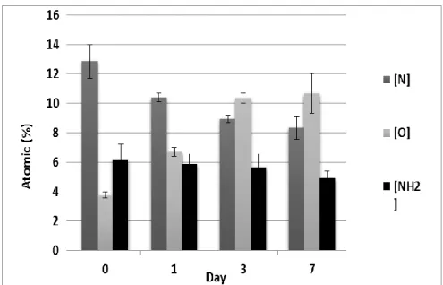
4.3.1.4.2 Ageing under Wet Conditions ... 55
4.3.2 Cell Adhesion, Viability and Proliferation on Bare and L-PPE:N-Coated Mat Substrates ... 56
4.3.3 Cell Resistance to Laminar Shear Stress ... 60
CHAPTER 5 ARTICLE 2: PLASMA-ETCHING FOR CONTROLLED MODIFICATION OF
STRUCTURAL AND MECHANICAL PROPERTIES OF ELECTROSPUN PET SCAFFOLDS ... 65
5.1 Introduction ... 67
5.2 Experimental Part ... 70
5.2.1 Fabrication of Aligned Nanofibrous PET Scaffolds ... 70
5.2.1.1 Electrospinning ... 70 5.2.1.2 Plasma Etching ... 71 5.2.1.2.1 Low-Pressure ... 71 5.2.1.2.2 Atmospheric Pressure ... 71 5.2.1.2.3 Plasma Asher ... 72 5.2.2 Materials Characterization ... 72
5.2.2.1 Scanning Electron Microscopy (SEM) ... 72
5.2.2.2 Mat Thickness ... 72
5.2.2.3 Quantification of Fiber Alignment ... 73
5.2.2.4 Porosity ... 73
5.2.2.5 X-Ray Photoelectron Spectroscopy ... 73
5.2.2.6 Static Contact Angle (SCA) Measurements ... 74
5.2.2.7 Wicking Properties... 74
5.2.2.8 Tensile Testing ... 74
5.2.2.9 Low-cycle Strain-controlled Accelerated Fatigue Testing ... 75
5.2.2.10 Intrinsic Viscosity and Molecular Weight ... 75
5.2.2.11 Differential Scanning Calorimetry (DSC) ... 76
5.2.3 Biological Testing... 76
5.2.3.1 Cell Culture and Seeding ... 76
5.2.3.2 Cell Adhesion and Growth ... 77
5.2.3.2.2 Scanning Electron Microscopy (SEM) ... 77
5.2.4 Statistical Analysis ... 78
5.3 Results and Discussion ... 78
5.3.1 Physical Properties of Pristine and of Etched Samples ... 78
5.3.1.1 Fiber Alignment and Mat Thickness ... 78
5.3.1.2 Measurements of Pore Parameters and Porosity ... 79
5.3.1.3 Scanning Electron Microscopy (SEM) ... 80
5.3.2 Surface-Chemical (XPS) Analyses ... 82
5.3.3 Contact Angle (SCA) Measurements ... 82
5.3.3.1 Wicking Properties... 83
5.3.4 Tensile Tests ... 83
5.3.4.1 Low-cycle Strain-controlled Accelerated Fatigue Testing ... 86
5.3.4.2 Intrinsic Viscosity and Molecular Weight ... 87
5.3.5 Differential Scanning Calorimetry (DSC) ... 88
5.3.6 Cell Adhesion, Viability and Proliferation on Pristine and Plasma-Etched Substrates ... 89
5.3.6.1 Cell Adhesion and Growth ... 89
5.3.6.2 Cell Morphology ... 90
5.4 General Discussion and Conclusions ... 91
CHAPTER 6 ARTICLE 3: COMBINING ELECTROSPUN FIBER MATS AND BIOACTIVE COATINGS FOR VASCULAR GRAFT PROSTHESES ... 94
6.1 Introduction ... 96
6.2 Materials and Methods ... 98
6.2.1 Materials ... 98
6.2.2 Fabrication of Random and Aligned Bioactive Nano-fibrous Scaffolds ... 98
6.2.2.1 Electrospinning ... 98
6.2.2.3 CS Grafting on the LP-coated Mats ... 99
6.2.2.4 EGF Oriented Immobilization ... 100
6.2.3 Characterization of Bioactive Scaffolds ... 100
6.2.3.1 Mat Morphology ... 100
6.2.3.2 Chemical Composition ... 101
6.2.3.3 Protein Adsorption Measurements ... 101
6.2.3.4 E-EGF Quantification by ELISA ... 101
6.2.4 Biological Testing... 102
6.2.4.1 HUVEC Adhesion and Growth ... 102
6.2.4.2 Cell Alignment and Morphology ... 103
6.2.4.3 HUVEC Resistance to Laminar Shear Stress ... 103
6.2.4.4 VSMC Adhesion, Growth and Survival ... 103
6.2.4.5 Histology ... 104
6.2.5 Statistical Analysis ... 104
6.3 Results and discussion ... 104
6.3.1 Morphology of Random and Aligned Scaffolds for Lumen ... 104
6.3.2 Morphology of Aligned Scaffolds for Medial Layer ... 105
6.3.3 Surface Chemistry and Depth-Dependence ... 105
6.3.4 Protein Adsorption ... 106
6.3.5 Effect of Fiber Orientation and Bioactive Coatings on HUVECs ... 107
6.3.6 VSMCs: Bioactivity of Coatings on Scaffolds for the Media Layer ... 111
6.3.6.1 Kcoil Grafting and EGF Capture - Quantification by ELISA ... 111
6.3.6.2 VSMC Adhesion and Growth ... 111
6.3.6.3 VSMC Survival in Serum-Free Medium ... 112
6.3.7 Combining Bioactive Coatings and Electrospun Mats: A Promising Approach for VG .... 113
6.5 Supporting Information ... 115
CHAPTER 7 GENERAL DISCUSSION & RECOMMENDATIONS FOR FUTURE RESEARCH . 119 7.1 Electrospun Nanofiber Scaffolds and Plasma Polymerization for VG applications ... 119
7.2 CS Grafting on Plasma-Polymerized Electrospun Mats for Stable Endothelialization ... 123
7.3 Combination of Electrospinning and Plasma-Etching for VG Applications ... 126
7.4 CS and Oriented Tethered EGF for Medial Layer of VGs ... 129
CONCLUSION ... 131
LIST OF TABLES
Table 4.1 Porosity and pore properties of electrospun mats, bare and L-PPE:N-coated (n=4). .... 52 Table 4.2 Mechanical properties of bare and L-PPE:N-coated electro-spun PET mats under dry and wet conditions (three experiments, at least 12 samples in each experiment). Young’s modulus was calculated in the linear portion of the stress-strain curve. Data are presented in comparison with values from the literature………54 Table 5.1 Process conditions used to produce the present electrospun aligned PET mats……….70 Table 5.2 Average fiber diameter and porosity of electrospun mats, pristine and plasma-etched.80 Table 5.3 Surface-chemical compositions of pristine and plasma-etched electrospun mats. ... 82 Table 5.4 Static contact angle & wicking time of pristine and plasma-etched electrospun mats...83
Table 5.5 Inherent and intrinsic viscosities and viscosity molecular weights for pristine and plasma-etched mats………..…...88
Table 6.1 Process conditions used to produce the electrospun random and aligned ePET mats...99 Table 6.2 XPS-based chemical compositions of bare and coated aligned mats for the media layer (AM) and their depth-dependence (n=3)……….……….106
LIST OF FIGURES
Figure 2.1 Schematic of atherosclerosis disease ... 4 Figure 2.2 Schematic of balloon angioplasty and stenting ... 6 Figure 2.3 Schematic of the commonly used saphenous vein and internal mammary artery graft for CABG ... 7 Figure 2.4 Structure of native blood vessels. ... 10 Figure 2.5 Morphological structure of woven (A); knitted (B) PET, ePTFE grafts (C). ... 14 Figure 2.6 a) Schematic diagram of the electrospinning process; b) SEM images of PET
…….electrospun nanofibers………...………15
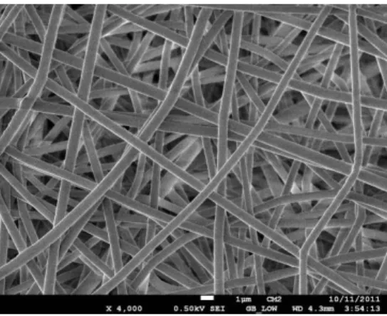
Figure 2.7 Typical stress-strain curve of the electrospun mats (a), the bulk polymer sample (b) and ePTFE VGs (c). ... 18 Figure 2.8 Surface modification techniques of electrospun nanofibers: (A) Plasma treatment or wet chemical method; (B) Surface graft polymerization. ... 26 Figure 2.9 A schematic diagram of a capacitively coupled plasma reactor. ... 27 Figure 2.10 Schematic illustration of the grafting steps for the oriented EGF immobilization on CS and CMD. The grafting of CS or CMD layers on aminated surfaces was followed by the chemical grafting of cysteine-tagged Kcoil peptides using EMCH as heterobifunctional linker. Remaining EMCH thiol-reactive groups were deactivated using cysteine molecules. Ecoil-tagged EGF proteins were captured on the surface via the reversible E/K coiled–coil interaction . ... 33 Figure 4.1 SEM micrograph of a plasma-coated electrospun PET nano-fiber mat; no distinction was possible between pristine (bare) and plasma-coated materials (scale bar: 1 µm). ... 50 Figure 4.2 Distributions of fiber diameters, as-prepared (ePET); after deposition of L-PPE:N (ePET-LPPE:N). ... 51 Figure 4.3 Pore-size distributions of pristine (bare) and L-PPE:N coated electrospun PET nanofiber mats (n=4). ... 52
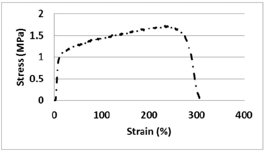
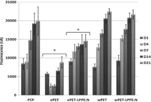
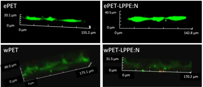
Figure 4.4 Typical tensile test (stress-strain) results for a nano-fibre mat; curves corresponding to bare and L-PPE:N-coated samples had very similar characteristics. ... 54 Figure 4.5 Ageing of L-PPE:N-coated mats after immersion in Milli-Q water for various durations, namely 1, 3, and 7 days (XPS; n=3). ... 56 Figure 4.6 Growth of HUVECs on different bare and L-PPE:N-coated substrate surfaces, after different culture times (PCP: tissue-culture polystyrene; ePET: electrospun mats; wPET: woven Dacron® fabric; LPPE:N: L-PPE:N-coated) (n= 9 for each) ... 57 Figure 4.7 Confocal microscopy images of immunofluorescence-stained HUVECs on the various substrates identified at the top; different rows represent days 1, 7 and 21 of culture (scale bar: 200 µm). The bottom row shows Z-stack images after 21 days. ... 59 Figure 4.8 SEM micrographs of electrospun nanofiber mats with HUVECs after 21 days of growth: a) bare mat (ePET); b) mat after L-PPE:N coating; c) bare woven PET (wPET, Dacron®); d) woven PET after L-PPE:N coating (scale bar: 100µm) ... 59
Figure 4.9 HUVECs’ resistance to laminar shear stress (15 dynes/cm2, 1h), evaluated by
AlamarBlue assay (n= 12 for each mat).. ... 61 Figure 4.10 SEM micrographs of bare (a,c) and L-PPE:N-coated (b,d) electrospun nanofiber (ePET) mats: a,b) under static conditions; c,d) under shear (scale bar: 100µm) ... 61 Figure 5.1 Two-dimensional FFT analysis of scaffold anisotropy; (A) SEM micrograph of pristine aligned electrospun nanofiber sample; (B) Image frequency plot; (C) 2D FFT alignment plot for the corresponding SEM micrograph. ... 79 Figure 5.2 SEM micrographs of electrospun aligned PET nano-fiber mats; effects of different plasma-etch treatment processes: (A) O2 “LP”-type plasma etching; (B) Ar/10% O2
“LP”-type plasma etching; (C) “HP” corona discharge; D) Plasma-asher (scale bar: 1 µm). ... 81 Figure 5.3 Effect of etch duration on mechanical properties of pristine and plasma-etched aligned ePET mats (three experiments, at least 12 samples in each experiment). (A) Young's modulus; (B) tensile strength; (C) elongation at break. ... 85 Figure 5.4 Mechanical properties of pristine and plasma-etched aligned ePET mats (three experiments, at least 12 samples in each experiment). (A) Young's modulus; (B) tensile
strength; (C) elongation at break; (D) yield strength. Yield strain did not change significantly for plasma-etched samples compared with pristine ones. ... 86 Figure 5.5 Strain-stress diagrams (loading and unloading) for pristine and plasma-etched aligned ePET mats, at cycle numbers 1 and 1 000 000. ... 87 Figure 5.6 DSC thermograms for PET pellet, pristine and plasma-etched ePET mats, during first heating. ... 89 Figure 5.7 Adhesion 24 h and growth 7 d of VSMCs on pristine and plasma-etched substrate (PCP: tissue-culture polystyrene; ePET: electrospun mats; e-PET-Asher: plasma-etched mats) (n = 8 for each) ... 90 Figure 5.8 SEM micrographs of electrospun nanofiber mats with VSMCs after 7 d of growth: (A) pristine mat (ePET); (B) mat after plasma-etching (scale bar: 50 µm). ... 91 Figure 6.1 SEM and 2D FFT images (insets) of (A) random (RL), (B) aligned (AL) mat for the luminal layer; and (C) aligned (AM) mat for the media layer (scale bar: 10 µm). ... 105 Figure 6.2 Fluorescence intensity of adsorbed Texas Red-BSA (0.2 mg/mL) on bare AM, AM+LP-, and AM+LP+CS-coated mats as a function of depth (n=10). ... 107 Figure 6.3 Adhesion (day 1) and growth (day 7, 14 and 21) of HUVECs on bare and coated random (RL) and aligned (AL) mats. Mean ± SD (n ≥ 6). ... 108 Figure 6.4 SEM images of HUVECs after 21 days of cell culture on a) bare and coated random (RL); b) bare and coated aligned (AL) ePET mats (scale bar: 100µm). ... 108 Figure 6.5 a) z-stack confocal micrograph of HUVECs grown (D21) on an AL mat (live cells in green); b, c) confocal micrographs of HUVEC adhered (at D1) on LP-coated (b) random (RL) and (c) aligned (AL) mats (cytoskeletal F-actin in green, nucleus in blue, electrospun fiber direction indicated by arrow); d) typical cell-cell interactions (VE-cadherin, in white); e) cell focal adhesion points (vinculin, in red) on LP-coated random (RL) mat at D7 (scale bar: 75 µm). ... 109 Figure 6.6 HUVEC retention after laminar shear stress (15 dynes.cm-2,1h), evaluated by AlamarBlue assay (n=4). ... 110
Figure 6.7 Adhesion after 24 h (D1) and growth after 7 days (D7) of VSMCs on bare and coated substrates [AM: bare aligned mats; (n=8 for each)]. ... 111 Figure 6.8 Histological section of an LP-coated AM mat, demonstrating cell infiltration (day 21; H&E staining, scale bar: 100 µm). ... 112 Figure 6.9 VSMC survival on bare and coated aligned (AM) substrates (LP+CS+EEGF: EGF immobilized on LP+CS-coated mats; AM+LP+CS+EGF(sol); LP+CS-coated mats with soluble EGF added in medium) (mean + SD; n=6) ... 113
LIST OF SYMBOLS AND ABBREVIATIONS
1-ethyl-3-(3-dimethylaminopropyl)carbodiimide EDC
aligned A
atmospheric pressure plasma HP
chondroitin sulfate CS
coronary artery bypass graft CABG
coronary artery disease CAD
dichloromethane DCM
dielectric barrier discharge DBD
differential scanning calorimetry DSC
electrospun PET ePET
endothelial cell EC
endothelial progenitor cells EPC
enzyme-linked immunosorbent assay ELISA
epidermal growth factor EGF
expanded poly(tetrafluoroethylene) ePTFE
extracellular matrix ECM
fast fourier transform FFT
growth factor GF
Hematoxylin-Eosin H&E
high-voltage HV
human umbilical vein endothelial cells HUVECs
hyaluronic acid HA
intimal hyperplasia IH
left anterior descending LAD
left internal mammary artery LIMA
low-pressure plasma LP
mercury intrusion porosimetry MIP
methacrylic acid MAA
N-hydroxysuccinimide NHS
optical density O.D.
percutaneous coronary intervention PCI
phosphate buffered saline PBS
plasma-polymerization PP
plasma-polymerizd allylamine PPAAm
poly(ethylene terephthalate) PET
polycarbonate urethane PCU
polyethylene glycol PEG
polyurethane PU
Low -pressure LP
Low-pressure primary-amine rich plasma polymer coating
L-PPE:N / LP
random R
scanning electron microscopy SEM
small-diameter vascular grafts SDVGs
static contact angle SCA
trifluoro-acetic acid TFA
trifluoromethyl) benzaldehyde TFBA
Vascular Endothelial Growth Factor VEGF
vascular graft VG
vascular smooth muscle cells VSMCs
woven PET wPET
CHAPTER 1
INTRODUCTION
Cardiovascular diseases are the leading cause of death worldwide [1, 2]. Small-diameter blood vessels in the body, including fine arteries of the heart and limbs, have a high prevalence of occlusion [3]. Bypass grafts from the patients’ own veins or arteries are currently the only therapeutic approach when endovascular procedures (angioplasty and stenting) are not feasible or successful: A frequent major obstacle in bypass grafts is that many patients cannot provide suitable veins or arteries, due to previous surgery or antecedent vascular disease. Consequently, to address this vital demand, development of prosthetic VGs has been a rapidly growing area of research [3].
Current off-the-shelf large diameter prosthetic VGs such as expanded poly(tetrafluoroethylene) (ePTFE) or woven poly(ethylene terephthalate (PET Dacron®) have shown poor
endothelialization and compliance mismatch, which lead to lack of patency when used for small diameter vessels (below 6 mm) [4]. To overcome these issues, researchers have introduced electrospun nano/micro-fiber scaffolds which possess adequate structural and mechanical properties to imitate the extracellular matrix (ECM) of the native blood vessels. These scaffolds offer great promise by possessing interconnected open structure with high porosity and surface area. Furthermore, mechanical properties of the scaffolds can be optimized to fine-tune those of native blood vessels.
While the structural and mechanical characteristics of the graft is of great importance in its performance and success, a critical design requirement for small-diameter VGs is the formation of a continuous monolayer of endothelial cells (ECs) on the lumen of the VGs which remains stable under physiological shear-flow conditions. To that purpose, seeding autologous ECs on the lumen side of the graft prior to implantation is commonly done, but its success is limited by low cell retention under flow and by the large pore size of conventional textiles that do not favor the formation of a continuous monolayer. Electrospinning enables the mimicking of the nanofibrous morphology of the ECM of blood vessels, but EC growth and retention on electrospun mats still remain a problem and present particularly severe challenges. To this aim, a suitable strategy is needed to provide the requisite strong cell-adhesion. Among the different techniques employed to improve cell adhesion and biocompatibility of polymeric scaffolds, several focus on the immobilization of bio-molecules that function as anchors for adhesion of cultured cells [5, 6]. A
particularly powerful method used to promote bio-molecule immobilization and eventually cell-adhesion is plasma-polymer deposition. Plasma-polymerization is a versatile approach for depositing polymer-like coatings with various selected functional groups (e.g., hydroxyl-, carboxyl-, or primary amine groups), which can enable further biomolecule grafting (e.g., ECM components, proteins and growth factors) and promote cell adhesion [7-9]. Therefore, this thesis aims at increasing compliance and endothelialization of VGs by combining 3D electrospun nanofiber matrices and bioactive coatings prepared by plasma-polymerization.
Chapter 2 provides an overview of the literature addressing the clinical significance of cardiovascular disease (intimal hyperplasia (IH) & atherosclerosis) in small-diameter blood vessels. A review of coronary artery disease and treatments, including bypass grafting, angioplasty, and stenting are then presented. Clinically available synthetic vascular prostheses are presented and the limitations of commercial materials SDVGs is discussed. Then, a review of electrospinning and the polymer scaffold fabrication technique; including basic concept and process parameters optimization specifically for VG development, are reviewed. The requirements of engineered SVGDs and the motivation for using electrospun scaffolds are then presented. Surface modification techniques including immobilization of bioactive coatings to promote cell-adhesion, growth, survival and in-vitro endothelialization are also discussed in detail. Based on the literature review, hypotheses are made and specific objectives are defined for this thesis that are presented in Chapter 3. The next three chapters present the three papers forming the core of the thesis. Chapter 4 of this thesis (Paper 1, published in Macromolecular Bioscience [10]) deals with fabrication and characterization of morphological, physico-chemical, mechanical and biocompatibility properties of random electrospun nanofiber mats and the benefit of a plasma polymer coating. We showed that this combination led to finely controlled structural, mechanical, and surface properties that are required for confluent EC monolayer on VGs. EC-adhesion, -growth, and -retention under shear-induced flow were characterized.
Chapter 5 (Paper 2, published in Plasma Processes and Polymers [11]) focuses on the fabrication of the aligned scaffolds with large pore size for subsequent VSMC-seeding that possess optimal mechanical, morphological and surface-chemical properties in the media layer. The fabricated ePET nano-fibers are radially highly oriented; in order to bring their mechanical properties in line with those of natural blood vessels, a substantial reduction in Young’s modulus has to be attained. Therefore, in this research, electrospinning and plasma etching are combined
to fulfill those criteria. Three different plasma-etching techniques are investigated: (i) atmospheric pressure (“HP”) corona discharge in air, low-pressure (ii) radio-frequency (r.f.) discharge, and (iii) discharge in a microwave plasma asher. The best technique without visible damage to the fibers, changes in surface composition and improved wettability is chosen for further VSMC adhesion and growth experiments.
Chapter 6 (Paper 3, published in Biomacromolecules [12]) aims to use biomolecules’ immobilization to further improve the cell adhesion, growth, survival and retention on the electrospun PET scaffolds for the luminal and media layers. As previously shown in our team, grafting bioactive coatings including chondroitin sulfate on nitrogen-rich plasma coating prevents platelet adhesion while promoting HUVEC adhesion and growth on the flat surfaces [13]. We therefore hypothesize that these bioactive coatings on electrospun PET mats can enhance HUVEC adhesion, growth, and their resistance to detachment. In addition, EC alignment in the direction of blood flow in the natural arteries is known to increase the cells capability to resist detachment under shear stress. This is typically achieved by a long and resource consuming method involving in vitro fluid flow preconditioning in a bioreactor prior to implantation. But, a recent study has shown an improvement in EC retention by tuning the topography (e.g., orientation) of electrospun fibers [14]. Therefore, we also investigate EC resistance to shear stress by tuning electrospun alignment and immobilization of bioactive coatings.
In Chapter 7, the general discussion, including the recommendations and limitations are presented, followed by the conclusion.
CHAPTER 2
LITERATURE REVIEW
2.1 Clinical Significance of Intimal Hyperplasia & Atherosclerosis
Cardiovascular diseases (CVDs) are the leading cause of death worldwide [1]. An estimated 85.6 million American adults (>1 in 3) have more than one type of CVD. Of these, 43.7 million are estimated to be ≥60 years of age. Small-diameter vessels (below 6 mm) in the body, including fine arteries of the heart and limbs have high prevalence of occlusion. This is caused by intimal hyperplasia (IH), which usually precedes atherosclerosis and eventually leads to distal tissue ischemia such as infarction in the case of coronary disease [15], as shown in Figure 2.1. There can be significant variability in which size of arteries and locations are affected in individual patients, although atherosclerosis is often a systemic disease. IH gradually happens by formation of the multi-layer of the cells on the elastic membrane of the arterial wall and expressing α-smooth-muscle actin [16]. The pathology of small-vessels disease (e.g., coronary) comprises a number of distinct features such as IH, appearance of foam cells/macrophages and cholesterol buildup, platelet aggregation and thrombogenesis, inflammation, etc. These features often overlap and enhance each other. IH usually refers to the cellular morphogenesis caused by a cell proliferation/differentiation process [17].Figure 2.1 Schematic of atherosclerosis disease from: https://stanfordhealthcare.org
2.2 Current Therapies and Limitations
Treatment options for coronary artery disease (CAD) depend on various factors, including severity and extent of the disease, type of symptoms such as chest pain and shortness of breath, overall heart function, other medical conditions such as diabetes, peripheral artery disease, and prior stroke or heart attack. Drug therapy has been used for decades to combat IH and atherosclerosis. Overall, it has not been satisfactory. Therefore, several approaches have been proposed to treat CAD, including angioplasty, stenting and bypass grafting.
2.2.1 Balloon Angioplasty
Angioplasty-also known as percutaneous coronary intervention (PCI)- is a minimally invasive procedure with a low risk of complication. Angioplasty may especially be recommended if the chest discomforts (angina) due to reduced blood flow have not responded to medication and lifestyle changes. During the procedure shown in Figure 2.2, a catheter containing a small balloon on its tip is inserted at the site of the blockage and is expanded to widen the narrowed artery by compressing or flattening the atherosclerotic plaque.
2.2.2 Stenting
Most of the time, to keep the artery open and reduce the risk of renewed narrowing, a small metal coil (stent) is implanted in the clogged artery, as illustrated in Figure 2.2. Stenting, like angioplasty, is a minimally invasive procedure. Even with stenting, it is still possible for the coronary artery to narrow again. With bare-metal stents, such restenosis occurs in as many as 15% to 30% of patients depending on the type of stent. This percentage is much lower in patients who receive drug-eluting stents [18]. If restenosis occurs, patients may require another balloon angioplasty, stent procedure, or bypass surgery. Although stents have proven to be a safe and effective treatment, their use may, on rare occasions, result in what is known as stent thrombosis which may cause a heart attack.
Figure 2.2 Schematic of balloon angioplasty and stenting from: http://www.keyword-suggestions.com
2.2.3 Coronary Artery Bypass Graft (CABG)
Bypass grafts from the patients’ own veins or arteries constitute another therapeutic approach if interventional procedures (balloon angioplasty and stenting, used in cases of less than 70% occlusion [19]) are not feasible or successful. In CABG (Figure 2.3), which is performed in cases with a greater degree of occlusion, autologous veins or arteries from the patient are grafted to bypass partially or completely occluded coronary artery, thereby improving myocardial oxygenated blood supply and preventing infarction.
Different autologous vessels may be employed to establish cardiac revascularization. The use of arterial grafts for replacing the left anterior descending (LAD, a coronary artery) was established before [20], the left internal mammary artery (LIMA) being the vessel of first choice for this procedure. IMAs are usually patent for many years postoperatively (10-year patency >90%) [21, 22] because of the fact that <4% of IMAs develop atherosclerosis, and only 1% have atherosclerotic stenoses of hemodynamic significance [23].
Reversed saphenous vein grafts (SVGs) are commonly used in patients undergoing CABG. Their disadvantage is a declining patency with time: 10% to 25% of them occlude within 1 year of
CABG [24]; an additional 1% to 2% occlude each year during the 1 to 5 years after surgery; and 4% to 5% occlude each year between 6 and 10 years postoperatively. Therefore, 10 years after CABG, 50% to 60% of SVGs are patent, only half of which have no angiographic evidence of atherosclerosis [25].
In general, autologous graft shows great promise in CABG procedure since it has the natural architecture. It is also a living, non-thrombogenic endothelium, is biocompatible, and has encouraging surgical handling characteristics. SVs have shown structural and functional changes leading to thrombosis, calcification and premature occlusion of the graft, while an autologous artery is more robust and longer-lasting.
A recent trial comparing CABG and PCI, reviewed the records of nearly 190,000 patients 65 years or older with multi-vessels disease. 86,244 underwent CABG and 103,549 underwent PCI. The median follow-up period was 2.67 years. At 1 year, there was no significant difference in mortality between the groups (6.24% CABG versus 6.55% PCI; risk ratio, 0.95). At 4 years, there was lower mortality with CABG than with PCI (16.4% versus 20.8%; risk ratio, 0.79) [26]. A major obstacle in bypass grafts is that many patients (5-30%) cannot provide veins or arteries suitable for grafting, due to previous surgery or antecedent vascular disease. Consequently, considering the mentioned limitations for the above VG alternatives and to address this vital demand, the development of prosthetic VGs has been a rapidly growing area of research [27].
Figure 2.3 Schematic of the commonly used saphenous vein and internal mammary artery graft for CABG; from: http://biology-forums.com
2.3 Clinically Available Synthetic Vascular Prostheses
There have been growing investigations to find alternate sources to mimic the structural and mechanical performance of native blood vessels, due to the high demand for bypass graft operations. Prosthetic materials that are currently used clinically are woven or knitted poly(ethylene terephthalate) (PET, Dacron®), expanded poly(tetrafluoroethylene) (ePTFE,
Teflon®) as VGs for arteries with an inner diameter of more than 6 mm [28]. These materials
have been validated as successful grafts for large-diameter arteries in which high flow and low resistance leads to low rates of thrombosis and excellent rates of long-term patency. However, in the long term, several complications may happen for smaller size, depending on the diameter, including thrombosis and IH. Therefore, the graft success rate (high patency in the long run) is highly dependent on internal diameter, and it falls steadily as the diameter becomes smaller [29]. The mechanisms involved in the development of IH have been largely established. In humans IH develops as early as 6 weeks after grafting and leads to narrowing of the vessel lumen. Generally, in the case of large grafts, the occlusion mechanism is well-stablished in the literature. They trigger immune responses initiated first by plasma protein, followed by platelet adhesion, and the migration of ECs and SMCs [30]. These initially cause static aggregation of lipid and blood factors (thrombosis), surrounded by ECM and followed by a continuous excessive SMC in-growth and plasma protein deposits in the chronic phase, which is covered by a fibrous cap (IH). ePTFE exhibits a 5-year patency rate of 91 to 95% when implanted as an aortic graft [31]. Similar to Teflon®, Dacron® also shows low patency rate of 56% in young patients with premature atherosclerosis over 10 years [32].
2.4 Challenges of Prosthetic Grafts as Small-Diameter VGs
(SDVGs)
Small-diameter blood vessels experience low blood flow and high shear compared to medium and large diameter ones. This makes the synthetic SDVGs (< 6 mm i.d.) more prone to thrombus formation and IH. This phenomenon is more acute in SDVGs for the coronary, renal, and carotid arteries: especially after increased contact time of blood components with grafts, and the increased activation of blood coagulation, this would result in high rates of thrombosis and low
patency in SDVGs [33]. So far, a primary reason for the failure of SDVGs made from synthetic materials has been their thrombogenic characteristics, but clinical observation also comes up with possible evidence that the patency rates of small grafts are improved by matching the elastic properties (compliance) of the graft to that of natural artery. Although there is still controversy that ‘elastic mismatch’ per se is the cause of IH, it is generally accepted that mechanical factors are important in its genesis. These include disturbed flow at the anastomosis, leading to fluctuations in shear stress at the endothelium, injury due to suturing and stress concentration at the anastomosis [34].
For example, Hehrlein et al. [35] compared the patency of ePTFE (3-5 mm i.d.) and SV grafts and concluded that 86% of SV grafts, while only 59% of ePTFE grafts were patent after 1-year follow-up. Dacron SDVGs (3-4 mm i.d.) have not shown encouraging performance, as evidenced by low medium-term patency rates [35].
Researchers have been investigating strategies to minimize thrombosis in small grafts, and to ensure appropriate mechanical (compliance) properties similar to those of natural blood vessels. While many different approaches can be used to tackle the current issues for SDVGs, two are most commonly used: (1) endothelialization; and (2) tuning the mechanical (compliance) properties of the grafts [36].
2.5 Importance of VG Endothelialization
Figure 2.4 presents the structure of native blood vessels: The inner layer named intima, is composed of a monolayer of endothelial cells, ECs. The endothelium is a continuous semi-permeable, non- thrombogenic protective barrier in the blood vessel wall, which controls blood flow and vessel tone, platelet activation, adhesion and aggregation, leukocyte adhesion and SMC migration and proliferation [37].
Figure 2.4 Structure of native blood vessels [38].
Unfortunately, it has been shown that VGs do not spontaneously endothelialize in situ/in vivo due to low initial EC attachment, spreading and growth.
The EC monolayer formed on synthetic VGs was observed to be less than 10% of physiological levels, compared with EC of native vessels [39]. ECs possess limited capacity for regeneration. After about 70 cell cycles, ECs can no divide and therefore, currently available VGs implanted into humans manifest limited EC ingrowth, typically not extending beyond 1-2 cm of the anastomoses [36].
This can also be explained by poor cell-adhesive properties as well as the structure and morphology of the grafts.. Therefore, graft patency is very limited for SDVGs below 6 mm, due to resulting thrombosis: Adhesion and agglomeration of platelets occur on the impaired endothelialized grafts, which is the main reason for thrombosis. Thus, it is necessary to accelerate EC attachment and proliferation on the internal surface, especially under blood flow conditions, to establish good long-term patency [40].
A promising method to improve the anti-thrombogenic properties of VGs is to seed ECs or capture endothelial progenitor cells (EPC) so as to form a complete monolayer on the lumen of VGs [41, 42]. Seeding of ECs provides an interface between the blood flow and the underlying VG, one that improves resistance of VGs to thrombosis and IH. Two approaches can be proposed: 1) in vitro pre-seeding prior to implantation; 2) promoting in vivo endothelialization
EC monolayer formation by in-vitro cell seeding comprises EC-adhesion to the graft surface, which takes place over a period of weeks; preferably within a shorter time, ECgrowth or -proliferation leads to confluent EC layer formation [43]. Several studies showed that in vitro endothelialization of grafts prior to implantation decreases thrombogenic complications and improves long-term patency [42]. These techniques and their limitations are described in more details in the next section.
2.5.1 EC Seeding and Maturation Techniques
Three main techniques have been employed by researchers for seeding and maturation of the grafts: (1) a single-stage procedure, (2) a two-stage procedure, and (3) pre-conditioning in a bioreactor.
In (1), developed by Herring et al. [44], the ECs are harvested and then immediately seeded on grafts. In order to assure a successful outcome, the harvested cell density should be high. In subsequent randomized clinical trials, EC-seeded ePTFE resulted in increased patency rates of arterial bypass grafts up to 9 year follow-up [45]. A major obstacle for single-stage seeding is the weak adhesion and possible detachment (70%) of ECs from the lumen when exposed to shear force and cyclic strain due to blood circulation a few minutes or hours after exposure to pulsatile flow [46].
In (2), ECs are extracted from the patient’s vein, artery, subcutaneous fat, or blood as progenitor cells. They are then cultured for a prolonged period in order to increase the number of cells, before seeding on the lumen, where they proliferate until confluency for 2-4 weeks in static culture before implantation [47]. In a clinical study, seeding of 4mm precoated Gore-Tex coronary with fibrin glue, including 5 ng/mL Human Basic Fibroblast Growth Factor (hbFGF), showed a 90% graft patency rate after 52 weeks post-implantation [48]. However, this procedure is time-consuming and labor-intensive, has the risk of contamination and infection within the cell culture medium, and risk of inefficient proliferation of the cells with time [40]. These render it impractical in emergency situations in clinical settings. Moreover, the ECadhesion and -resistance to flow-induced shear are impaired once the bare or unmodified graft is implanted in-vivo, leading to probable cell-detachment [14].
To promote EC attachment and high retention rate under physiological condition, shear stress preconditioning has been used for decades [49]. In this procedure, cells are gradually subjected to low shear stress in a bioreactor in order to mature the EC layer. This stategy has shown significant impact on EC cell retention after in-vivo implantation [49]. In all cases, however, limited cell retention can be at least partly explained by inertness of these biomaterials, which justifies the use of bioactive coatings as a possible solution. In addition, the graft morphology has a large impact on the formation of a confluent EC monolayer. In that sense, small pores on the woven/non-woven structure of grafts facilitate ECs to form an adherent monolayer on the top surface and ensures satisfactory endothelialization.
2.6 Importance of Mechanical (Compliance) Properties
Most commercial VGs (Dacron® and Teflon®) suffer from unsatisfactory mechanical properties
including low compliance, and high stiffness or rigidity [27]. To simplify a complicated physical phenomenon in a clinical setting, the “compliance” of a tube has been defined to express a change of diameter with changing pressure. In general, it has been found that as compliance mismatch increases, graft patency decreases [50]. Compliance mismatch prevents a synthetic graft from stretching at the surgically-made connection between it and the native blood vessel - the so-called “anastomosis region”. This causes the frequency of the pulsatile blood flow to be dampened, leading to an increase in the flow velocity, a concomitant increase in wave reflection and energy loss. The extent to which the pulse amplitude is dampened depends upon the length of the rigid portion [51], its lack of elasticity causing turbulence and shear stress, which in turn produce inconsistent blood flow profiles and damage to ECs. On the other hand, reduced shear stress can cause flow stagnation in affected areas, increasing the interaction between platelets and the vessel wall, and accumulation of chemokine factors. This promotes thrombosis and severe IH, hence eventual occlusion of the graft [50].
To prevent this scenario from occurring, a VG should closely match the compliance of the adjacent native blood vessel. Beside matching compliance, VGs should also have sufficient tensile stiffness to withstand forces related to vessel contraction and physiological blood pressure [52]. Therefore, the fabrication of synthetic VGs with mechanical properties similar to those of native blood vessels remains a challenge, and it has become a fast-growing area of research.
2.7 The Limitations of Commercial Materials as SDVGs
To develop “ideal” SDVGs with good patency rates, it is crucial to design a structure that mimics the native blood vessel ECM, and that matches its mechanical compliance (see above). Another key factor, also described earlier, is thrombo-resistance of the surface, which can be obtained via a complete, stable monolayer of ECs. Woven or knitted Dacron® (PET) fabrics with differing
degrees of porosity have been tested as SDVGs in some animal studies. Woven grafts are typically much less porous than knit ones, but all exhibit higher stiffness than native small blood vessels. To improve their bioactivity, different coatings have been investigated, for example gelatin, collagen, heparin, fibrin, and growth factors [53, 54]. The outcomes of those studies showed no significant reduction in thrombus formation, and impaired in-vivo endothelialization even with functional coatings [55, 56]. Expanded PTFE (ePTFE) with pore sizes between ca. 30µm and 100µm were developed by paste extrusion, followed by solvent evaporation, biaxial stretching and high-temperature sintering, but ePTFE is also less compliant than natural arteries and veins [50]. Despite its mechanical mismatch, ePTFE has gained some acceptance for peripheral vessel bypass, particularly for the femoropopliteal artery. Indeed, there have been debates about the superiority of ePTFE over Dacron®, and this controversy still persists. Bio-functionalization of ePTFE grafts has been attempted in order to improve their patency, for example fibrin / growth factor combinations [57, 58], but surprisingly no improvement was found in the animal models studied. As such, no solid conclusions could be drawn.
To overcome compliance mismatch of the above-described conventional materials, a less stiff, more elastic material has been sought, for example polyurethane (PU) [59, 60]. Polyester-based PU (PEU) grafts such as Estane® were used in an animal study, but with discouraging results due to its instability by hydrolysis or to enzymatic attack, or both [61]. Mitrathane®, a polyether PU (PEEU) graft is more stable under both acidic and alkaline conditions, but this graft is prone to the enzymatic stress cracking after implantation [62].
Vascugraft® polycarbonate urethane (PCU), using a spray technique to resolve the instability of
PEU and PEEU, produces microporous fibers with inter-connected pores. However, this graft also showed disappointing clinical results in a 15-patient study caused by early occlusion [63].
Therefore, there still exists an unmet need of a material to mimic the structural and mechanical performance of native blood vessels. The 3D network of blood vessels ECM has a fibrous structure [64]; woven and knitted Dacron and ePTFE are far from that fibrillar morphology, therefore they are inadequate to form an endothelial monolayer (Figure 2.5).
Figure 2.5 Morphological structure of woven (A); knitted (B) PET; ePTFE grafts (C) from [65].
There have been a growing number of studies to design VGs with hierarchical structures having more ‘biomimetic’ topography and mechanical interactions of the native ECM. To this aim, scaffolds based on different techniques have been considered, generally by electrospinning, self-assembly, and phase separation [66, 67]. In the following, we shall focus on electrospinning.
2.8 Electrospinning
2.8.1 Principle
Electrospinning, a versatile technique for fabricating nano/micro fibers, has great potential for developing a microenvironment that mimics natural ECM [68, 69]. It is simpler and more efficient than other competing techniques like self-assembly or phase separation, being able to
A B
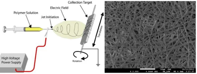
produce a highly porous (>70% porosity) network of continuous ultrafine fibers ranging from nanometer to micrometer diameters. The first patent about electrospinning had already described an apparatus for producing polymer filaments that took advantage of electrostatic repulsions between surface charges [70]. In the early 1990s, that since-forgotten technology was reintroduced to fabricate thin fibers of various organic polymer [71]. By applying an electric field, polymer solution or melt is drawn from a spinneret to a collector. A high voltage is required to overcome surface tension. A so-called “Taylor cone” is formed, in which the narrow jet is accelerated towards the grounded or oppositely-charged collecting target, while the solvent evaporates [67]. For producing VGs, a rapidly-rotating cylindrical mandrel can be used as the target / collector, to produce a tubular scaffold. At low rotational speed, fibers organize randomly, while at high speed the fibers will align near-perpendicularly to the axis of rotation [72]. Figure 2.6 shows a schematic of the electrospinning process, and a SEM micrograph of electrospun nanofibers. Different fiber morphologies such as beaded-, ribbon-, porous fibers and core-shells, can also be fabricated [67]. A broad range of polymers and co-polymers with sufficiently high molecular weights can be employed, yielding fiber diameters ranging from several nanometers to micrometers. Electrospun nanofiber mats form non-woven, random or aligned sheets or arrays [73].
Figure 2.6 a) Schematic diagram of the electrospinning process; from http://www.people.vcu.edu/~glbowlin;
The fibers’ properties depend on many parameters like processing conditions, polymer solution, and ambient conditions. Solution characteristics include the molecular weight of the polymer, its concentration, its viscosity and surface tension, charge density, conductivity, and dielectric constant. Process variables include flow-rate, applied voltage, distance between needle-tip and collector, and the collector composition and geometry. Ambient conditions include temperature, humidity, and pressure [73]. Good understanding of these variables allows one to reproducibly fabricate defect-free nanofibers with controllable morphology.
2.8.1.1 Effect of Electrospinning Parameters on Structure and Morphology
As just mentioned, structure and morphology of electrospun fibers are determined by a synergetic interaction between those various sets of parameters [74]. For example, viscosity influences fiber diameter. It can initiate bead-like shape, and influences jet trajectory [75]. There is an optimal viscosity for obtaining continuous fibers, and a higher viscosity produces larger diameters and pore sizes [75]. A minimum solution concentration is required to form a bead-free fiber; below a critical concentration, a mixture of beads and fibers results [75].
Solution conductivity, another key player, mainly depends on polymer type and solvent. Increased electrical conductivity results in a reduced nano-fiber diameter [76]. Molecular weight of the polymer plays an important role in electrical and rheological properties [77], with high values producing larger fiber diameters and pore sizes, while lower ones favor bead formation rather than smooth fibers [78]. Polymer jet velocity is obviously influenced by flow rate. Tuning the latter governs the solvent evaporation time, hence the formation of smooth, uniform fibers [79].
Applied voltage plays an important role in stability of the Taylor cone. For example, increased voltage results in higher jet velocity and reduced fiber diameter, which eventually leads to beaded fibers [75]. Distance between needle-tip and collector changes fiber diameter and morphology of the final mat. A minimum distance is required to allow fibers to properly dry before depositing on the collector, but increasing distance reduces the fiber diameter and eventually leads to bead formation [75].
Ambient conditions also influence fiber diameter and morphology. For example, as temperature increases, solution viscosity decreases, resulting in smaller fiber diameters and pore sizes, while high humidity forms circular pores on the fibers [80].
2.8.1.2 Effect of Electrospinning Parameters on Mechanical Properties
Recent studies have shown strong correlation between mechanical properties of a VG and IH. The reader is reminded that compliance, the measure of VG diameter change with pressure, is one of the key factors to success or failure [50]. Despite high burst pressures and suture retention strengths, compliance values of PET and ePTFE are much below native vessel values [81]. As a result, the compliant natural artery will expand and contract to maintain constant wall shear stress, whereas a stiff synthetic graft resists those changes in diameter. As also explained earlier, this compliance mismatch perturbs blood flow, results in zones of recirculation, flow separation, and low wall shear stress at the endothelium [34] that, along with cell-biological factors, stimulate IH [29]. Therefore, a VG that closely matches native artery compliance can greatly improve long-term clinical success.
Native blood vessels consist of alternating layers of elastin and collagen, which provide both high burst pressure and high compliance (respectively 1680 ± 307 mmHg and 4.4 ±0.8%/mmHg 10-4
for the saphenous vein) [50, 82]. Reproducing these in synthetic VGs is very challenging, given that they are often inversely related. The hierarchical structure of alternating elastin / collagen in arteries provides for a low tensile modulus with high elastic recovery, accompanied by strong strain hardening response at higher strains [83]. A synthetic material that can mimic this stress-strain behavior will obviously better match the required compliance properties and thereby reduce danger of IH. For example, electrospun fiber diameter and alignment, both of which can readily be “tuned”, are known to influence mechanical properties [84-86].
Electrospun nanofiber mats exhibit unusual, and unique mechanical properties compared with macroscopic film structures [87]. Figure 2.7 shows that the stress-strain curve of an electrospun mat does not manifest “necking”, contrary to an injection-molded bulk polymer sample [86, 88].
(a) (b)
(c)
Figure 2.7 Typical stress-strain curve of the electrospun mats (a), the bulk polymer sample (b) and ePTFE VGs (c).
(a): authors’ result on random ePET mat; (b) from (http://www.hardiepolymers.com); (c): from [89].
In electrospun fibers, crystallinity and molecular orientation play important roles in determining the physical and mechanical properties of resulting mats [90]. For example, the amorphous fraction influences strength and elastic modulus of fibers, while the crystalline phase imparts dimensional stability. Therefore, both phases combine to govern the overall mechanical properties of fibers [86], while the tensile properties of mats also depend on the properties of individual fibers, as well as their mutual interactions and arrangements within the mats. Therefore, those properties are not easily explained [87]. For example, deformation of a single fiber depends on its diameter: below a critical value, tensile strength is observed to increase exponentially, while large fibers show bulk-like properties [86]. This can be explained by gradual ordering of the macromolecular chains and increased crystallinity [90].


![Figure 2.4 Structure of native blood vessels [38].](https://thumb-eu.123doks.com/thumbv2/123doknet/2347714.35301/34.918.286.659.113.387/figure-structure-native-blood-vessels.webp)
![Figure 2.9 A schematic diagram of a capacitively coupled plasma reactor [160].](https://thumb-eu.123doks.com/thumbv2/123doknet/2347714.35301/51.918.136.836.564.885/figure-schematic-diagram-capacitively-coupled-plasma-reactor.webp)