HAL Id: hal-01535056
https://hal.archives-ouvertes.fr/hal-01535056
Submitted on 8 Jun 2017
HAL is a multi-disciplinary open access
archive for the deposit and dissemination of
sci-entific research documents, whether they are
pub-lished or not. The documents may come from
teaching and research institutions in France or
L’archive ouverte pluridisciplinaire HAL, est
destinée au dépôt et à la diffusion de documents
scientifiques de niveau recherche, publiés ou non,
émanant des établissements d’enseignement et de
recherche français ou étrangers, des laboratoires
Semantic correspondence across 3D models for
example-based modeling
Vincent Léon, Vincent Itier, Nicolas Bonneel, Guillaume Lavoué,
Jean-Philippe Vandeborre
To cite this version:
Vincent Léon, Vincent Itier, Nicolas Bonneel, Guillaume Lavoué, Jean-Philippe Vandeborre. Semantic
correspondence across 3D models for example-based modeling. Eurographics Workshop on 3D Object
Retrieval 2017 (3DOR 2017), Apr 2017, Lyon, France. 7 p. �hal-01535056�
Eurographics Workshop on 3D Object Retrieval (2017) I. Pratikakis, F. Dupont, and M. Ovsjanikov (Editors)
Semantic correspondence across 3D models
for example-based modeling
V. Léon1, V. Itier2, N. Bonneel3, G. Lavoué3and J.-P. Vandeborre4
1Uraniom, Laval, France
2IMT Lille Douai, Univ. Lille, Département Informatique et Réseaux, F-59000 Lille, France 3Univ. Lyon, CNRS, LIRIS, France
4IMT Lille Douai, Univ. Lille, CNRS, UMR 9189 - CRIStAL - Centre de Recherche en Informatique Signal et Automatique de Lille, F-59000 Lille, France
Abstract
Modeling 3D shapes is a specialized skill not affordable to most novice artists due to its complexity and tediousness. At the same time, databases of complex models ready for use are becoming widespread, and can help the modeling task in a process called example-based modeling. We introduce such an example-based mesh modeling approach which, contrary to prior work, allows for the replacement of any localized region of a mesh by a region of similar semantics (but different geometry) within a mesh database. For that, we introduce a selection tool in a space of semantic descriptors that co-selects areas of similar semantics within the database. Moreover, this tool can be used for part-based retrieval across the database. Then, we show how semantic information improves the assembly process. This allows for modeling complex meshes from a coarse geometry and a database of more detailed meshes, and makes modeling accessible to the novice user.
Categories and Subject Descriptors(according to ACM CCS): I.3.5 [Computer Graphics]: Computational Geometry and Object Modeling—I.2.10 [Artificial Intelligence]: Vision and Scene Understanding—Shape H.3.3 [Information Storage and Retrieval]: Information Search and Retrieval—Search Process
1. Introduction
Modeling 3D shapes is a tedious task often performed by skilled artists. From the modeling of the global shape of a human to the sculpting of geometric details such as wrinkles or muscle bulges, technical skills, talent and time are necessary. These requirements make the task generally ill-suited to novice users.
Upon realizing that the space of possible shapes is often lim-ited – for instance, a human is composed of a head, a torso, two arms and two legs – researchers have recently resorted to the use of mesh databases and example-based modeling. To date, this has remained limited to sketch-based interfaces to query en-tire meshes [XXM∗13,FWX∗13], or to rigidly replace segmented parts of an input mesh with other parts from the database [KJS07,
CKGK11,CKGF13]. Even for experts, modeling often involves repetitive tasks that are more efficiently performed by re-using pieces of existing models in databases. These example-based ap-proaches are thus expected to benefit the expert as much as the lay-man. Alternatively, an option is to resort to parameterized shapes (e.g., Poser [Smi15] for humans and animals) but limiting the di-versity of the obtained results by a relatively small set of adjustable parameters.
We leverage recent advances in 3D mesh semantic description as
well as the development of mesh databases to propose an example-based modeling framework suitable for the modeling of smooth shapes by novice users. To do so, we first propose an efficient selec-tion tool that selects all regions similar in semantics to a brushed area within a mesh database. This makes use of a continuous se-mantic descriptor introduced by Léon et al. [LBLV16], that is, a high-dimensional descriptor able to discriminate between points sharing the same discrete label. Second, we show how semantic information also helps in the process of aligning and gluing shapes together. We demonstrate that our tool finally allows for the mod-eling of complex geometries by starting with a coarse 3D model and progressively refining it by replacing localized regions by re-gions of similar semantic (albeit geometrically different) within a database of more detailed meshes.
2. Related Work
Example-based shape modeling is an important challenge in com-puter graphics. The objective is to ease the designers’ work and speed up the production of 3D models. We can broadly classify existing techniques into: (1) manual editing tools and (2) part as-sembly based on consistent segmentation.
V. Léon & V. Itier & N. Bonneel & G. Lavoué & J.-P. Vandeborre / Semantic correspondence across 3D models for example-based modeling
Funkhouser et al. [FKS∗04]. In their approach, the user finds some parts of interest from an existing 3D shape database, cuts those desired parts using explicit scissoring, and glues them together to create a new shape. This approach introduces three main compo-nents: an interactive segmentation tool, a 3D local shape retrieval algorithm (to retrieve parts of interest) and a part composition tool. Several methods follow this framework, and enable a manual com-position/modification of a 3D shape [SBSCO06,SS10,TSS∗11].
Part assembly based on consistent segmentation. Tech-niques presented above have the drawback of requiring tedious manual mesh scissoring and composition. To fasten part re-trieval and composition, most recent methods pre-process the database by a compatible segmentation and labeling. Such consistent semantic labeling of a whole 3D shape database may be obtained by data-driven techniques [KH10,vKTS∗11], co-analysis [HKG11,SvKK∗11,vKXZ∗13] or by fitting a shape template [KLM∗13]. After this offline pre-process, each shape of the database is cut into consistent meaningful parts, often associated to semantic labels (e.g, harm, leg, torso and head in the case of humanoid models). Such consistent semantic labeling is perfectly suited for modeling by assembling parts. Indeed, this allows to have a direct correspondence between the semantic parts of all objects of the database and thus allows to easily compose parts. Kreavoy et al. [KJS07] were the first to use consistent segmentation for model composition. With their system, the user just has to click on a part of a target model to exchange it with another part (with the same label) from a different model. This idea was extended by Chaudhuri and Koltun [CK10] who introduce an algorithm for automatic suggestions of novel components to aug-ment a prototype shape. Chaudhuri et al. [CKGK11] improved this suggestion system by incorporating semantic relationships between parts, using a probabilistic model. Kalogerakis et al. [KCK12] considered a similar model for automatic component-assembly. Still based on a prior consistent shape labeling, Averkiou et al. [AKZM14] propose a low-dimensional parametrized space to explore easily the collection of 3D models and synthesize new arrangements of parts.
The main weakness of these techniques based on consistent seg-mentation/labeling is that their degree of freedom is limited by the pre-defined semantic domain. For instance it is impossible to glue an ear on the head of a 3D model, if these two components do not possess different labels in the database. On the other side of the spectrum, manual editing methods are purely geometric and thus lack semantic information that could help the editing process. In this context, from a manually selected region of interest, Kim et al. [KLM∗12] proposed a method to compute fuzzy correspon-dences on meshes from a non-segmented database. This method re-lies only on corresponding geometric features across the database meshes. More recently, a continuous semantic representation has been introduced recently by Léon et al. [LBLV16]. Given a seg-mented and labeled 3D mesh, their descriptor consists of a set of geodesic distances to the different semantic labels. This local mul-tidimensional signature effectively captures both the semantic in-formation (and relationships between labels) and the underlying geometry and topology of the shape. Therefore, it provides more
(a) Head (b) Foot (c) Hand
Figure 1: Illustration of the semantic descriptor of Léon et al. [LBLV16]. Here, a three-dimensional descriptor is considered, and each dimension represents the distance to points labeled as (a)Head, (b) Foot and (c) Hand respectively. Blue represents small distances while red represent larger distances.
precise results than the Kim et al. [KLM∗12] method. We rely on this representation to propose a new shape editing framework that bridges this gap between part assembly (which is too constrained by a prior segmentation) and manual editing (which requires te-dious manual operations).
3. Overview
Given a database of 3D shapes, our example-based modeling framework is illustrated in Figures 6 and 7. As offline pre-processing, all shapes are first segmented and semantically labeled, using one of the numerous existing mesh labeling meth-ods [KH10,HKG11,SvKK∗11,vKXZ∗13]. We also compute, from this discrete labeling, the continuous semantic descriptor from Léon et al. [LBLV16] (see Section4, Fig. 1). It computes, for each vertex, a multidimensional signature that describes its semantic context.
The user starts the modeling process with an arbitrary 3D shape from the dataset. Then, using a brush painting interface, the user can select an arbitrary region from this shape that needs to be re-placed (see Fig.7a). This input region is analyzed and approxi-mated by an ellipsoid in the space of the semantic descriptor (Sec-tion5). This fitted ellipsoid allows for a fast query of semantically similar target regions in the rest of the database (Fig.7b). The user can thus replace the input region by any of the retrieved target re-gions. The geometric replacement is done by first aligning both regions (Section6.1) and then smoothly merging the aligned mesh parts (Sec.6.2and Fig.7c). Those two steps do not consider only geometric criteria but also rely on the semantic description to pro-duce a realistic result.
4. Semantic description
Semantic labels are useful for defining the correspondence be-tween segments, an operation commonly performed in
example-c
based modeling [KJS07,XXM∗13]. However, defining a unique la-bel for each segment restricts its use to correspondences between segments, and thus may only be useful to replace entire mesh seg-ments. In practice, a user’s selection will often lie in-between two segments or represent a small subset of a segment. The user could as well be interested in a different level of detail: for instance, a user may want to select a foot, when the segmentation and labeling has produced a unique segment for the entire leg. We thus resort to a continuous extension of this labeling process, akin to soft seg-mentation.
To obtain such a continuous semantic description, we use the multidimensional descriptor of Léon et al. [LBLV16]. As input, this descriptor takes a segmented and labeled mesh along with a random sampling of each segment. Then, each dimension of the de-scriptor corresponds to one label, and its value is computed as the geodesic distance to the closest sample bearing this label. To com-pute this descriptor, we use the exact geodesic distance of Surazh-sky et al. [SSK∗05], making it robust not only to rigid transforma-tions, but also to changes in mesh resolution. Figure1illustrates different dimensions of the descriptor. This descriptor gives a con-tinuous notion of semantics – for instance, determining that a point is within the Head region but close to the Neck – while also carry-ing geometric information.
5. Correspondence and selection
The first step is to determine regions within a mesh database that are similar to the user selection on the input mesh. This similar-ity measure is taken as a semantic similarsimilar-ity, that is, the semantic descriptors within these regions should be similar in term of Eu-clidean distance between descriptors. This process leads to a corre-spondence between an input region and a set of semantically similar regions in the mesh collection.
To avoid disconnected or highly distorted regions, we represent the user selection by a high-dimensional axis-aligned ellipsoid in the descriptor space. Each axis of the ellipsoid corresponds to a se-mantic label and the axis length models how that particular label varies within the selected area. The ellipsoid representation is com-pact, fast to compute and allows for the easy matching of selected areas. In fact, given an ellipsoid representing a selection on the in-put mesh, retrieving a similar selection on any other mesh merely amounts to selecting all vertices falling within the ellipsoid in the descriptor space. It is however important to note that these ellipsoid live in the high-dimensional space of the semantic descriptors (with as many dimensions as labels) and that user selections on the 3D mesh need not be elliptical.
To find the parameters of the ellipsoid representing a selected area, we first initialize it with a bounding hypersphere encompass-ing the descriptors of all vertices within the selected area (Sec.5.1). We then refine it in an optimization step (Sec.5.2).
5.1. Initialization
An axis-aligned ellipsoid in an n-dimensional space is defined by the following equation:
n
∑
i=0
(xi− pi)2
a2i = 1 (1)
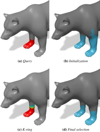
(a) Query (b) Initialization
(c) K-ring (d) Final selection
Figure 2: Overview of the selection and correspondence process. (a) Manual selection of a reference region on the paw. (b) Initial-ization with an hypersphere. (c) K-ring around the reference patch, for k= 3. (d) Final selection on the reference model with the ellip-soid. Vertices in blue are classified as part of the hypersphere or the ellipsoid. In (c), vertices in red are part of the original selec-tion, and vertices in cyan and yellow are part of the 3-ring around it.
where {ai}i=1..nare the parameters (axis) of the ellipsoid and p =
{pi}i=1..nits center.
Since we will rely on iterative optimization techniques, the ini-tial values for the {ai}i=1..nparameters have to be chosen carefully
so that they are not too far from the expected final values. For the initialization, we use a bounding hypersphere of radius r in the de-scriptor space H, with r defined as follows:
r= kd(p) − d(q)k2 (2)
where p is the center of the selected region in descriptor space, q is the selected vertex farthest from p in term of descriptors, and d is the semantic descriptor. Figure2aillustrates this initialization. As we can see in figure2busing this descriptor, the selection process accounts for symmetries.
5.2. Energy minimization
The ellipsoid parameters completely describe the user selection, thus they are used as a region descriptor for part-based retrieval.
V. Léon & V. Itier & N. Bonneel & G. Lavoué & J.-P. Vandeborre / Semantic correspondence across 3D models for example-based modeling
In order to compute the parameters of the ellipsoid that fits best the user selection S, we minimize the energy:
e=
∑
s∈ ˆS 1S sn∑
i=0 (di(p) − di(s))2 ai2 − 1 !2 (3)where di(s) is the ithdimension of the n-dimensional semantic
de-scriptor computed for vertex s and the center p. ˆSis the selected region S extended with a k-ring.
The energy term is computed for every vertex s inside the ref-erence selection and inside the k-ring around this region, as shown on Figure2c. The k-ring region is a set of negative examples which don’t belong to the selected region. They are used to evaluate the parameters of the ellipsoid. The indicator function1sevaluates the
consistency between the geometric selection and the semantic el-lipsoid. If a vertex is inside the selected area and its descriptor is inside the ellipsoid, then1s= 1 (we refer to them as positive
ex-amples). Likewise, if the vertex is outside of the selected area (but within a k-ring – typically k = 3) and its descriptor is outside of the ellipsoid, then1s= 1 (we call them negative examples). In every
other case,1s= 0 and the energy contribution for this vertex is not
computed (eq.4). 1s= 1 if ∑ni=0 (di(p)−di(s))2 ai2 < 1 and s ∈ S 1 if ∑ni=0(di(p)−di(s))2 ai2 ≥ 1 and s ∈ ˆS− S 0 otherwise (4)
This method allows for a tight ellipsoid, and prevents the ellip-soid to enclose too many vertices that do not belong to the initial brushed area. Using the k-ring around the user selection brings a set of negative examples, that are not part of the selection, to evaluate the parameters of the ellipsoid. Figure2cillustrate this k-ring for the previously considered selection.
The energy function minimization is performed using the COBYLA algorithm [Pow94] which supports derivative estima-tion, as the derivative of the energy does not have a simple closed-form expression due to the indicator function1s.
Given the optimized parameters of the ellipsoid, vertices are classified according to their descriptors. Figure2dillustrates this classification. We notice on Figure2dthat the descriptor accounts for symmetry. Compared to the hypersphere initialization, shown in Figure2b, the ellipsoid brings the selection closer to the reference query, shown in Figure2a.
5.3. Query on the database
Once optimal parameters of the ellipsoid are computed for the user selection, we obtain similar regions among other meshes by de-termining, for each vertex of these meshes, whether its seman-tic descriptor lies within the ellipsoid in the descriptor space. The vertex is selected if and only if its descriptor d is such that ∑ni=0
(di−pi)2
a2 i
< 1. The results illustrated in figure2d,4b,6b, and
7bare obtained using this method.
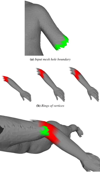
(a) Input mesh hole boundary
(b) Rings of vertices
(c) Semantic alignment of the target region with input mesh boundary Figure 3: Semantic alignment of the corresponding rings of ver-tices: a) mesh hole boundary, b) example of rings of vertices, c) the second ring is chosen as corresponding set of vertices and the target region is aligned with a rigid ICIP.
6. Automatic geometry transfer
Once the user has chosen a target region to replace the selected region from the input mesh, our algorithm performs a semantic-aware geometry transfer. First, we align both regions, and then, the target region is smoothly and realistically blended onto the input mesh.
6.1. Automatic alignment
Merging the target region to the input mesh first requires the to-be-exchanged regions to be aligned. Hence, the target region is first translated and scaled to fit the selected input region. After this coarse alignment, the selected region of the input mesh is removed.
c
Due to the semantic nature of our selection tool, this may result in several holes in the input mesh – for instance, if a user brushes a foot, both feet will be selected (Fig.2).
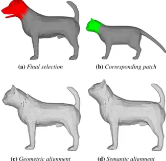
Then, the target region is associated with its closest hole in the input mesh and an iterative closest point (ICP) algorithm [BM92] is processed to stitch both meshes. Standard ICP uses geometric fea-tures such as the euclidean distance, curvature, and angle difference between normals to put vertices in correspondence and rigidly re-orient the target mesh region to the input mesh hole. However, us-ing only geometric information to compute these correspondences may result in unnatural stitching (e.g., see the cat’s head in Fig.
4c). To resolve this issue, we integrate the semantic descriptor in the ICP algorithm, by replacing the geometric correspondence by a semantic correspondence between vertices from the input mesh hole boundary and vertices from the target region. Our algorithm is the following, as illustrated in Figure3: we defines several rings of vertices on the target region, starting from the boundary and mov-ing away from it. We then select from these rmov-ings, the one that is the closest to the input mesh boundary with respect to its seman-tic descriptor. In pracseman-tice, we define the semanseman-tic distance sd(v, S0) between a vertex v from the input mesh boundary and a ring of vertices S0from the target region as:
sd(v, S0) = min
v0∈S0kd(v) − d(v
0
)k2. (5)
with d is the semantic descriptor. The distance between the input mesh boundary S and the ithring Si0is then given by:
d(S, Si0) = j=n
∑
j=0
sd(vj, Si0), (6)
The corresponding ring Sc0is then selected as argmin(d(S), Si0).
We can then find a correspondence between each vertex of Sc0and
S, as:
v0= argmin
x∈S0 c
wd(x, v), (7)
where wd(x, v) is a weighted sum taking in account the semantic descriptor and the geometry.
wd(x, v) = α1kv − xk2+ α2arccos(Nv− Nv)
+α3(cv− cx) + α4kd(v) − d(x)k2,
(8) where terms correspond respectively to the Euclidean distance between the vertices, the normal difference of the normals at the vertices, the difference in the local Gaussian curvatures at the vertices and the distance in the descriptor space at the vertices. We found the following weights to perform well in practice: α1= 0.2,
α2= 0., α3= 0.2, α4= 0.4.
This new semantic correspondence results in an improved ICP alignment, as compared to classical geometric ICP, as illustrated in Figure4.
6.2. Mesh fusion
Now that the target region is well aligned with the input mesh, and that corresponding surfaces are overlapping around their opened
(a) Final selection (b) Corresponding patch
(c) Geometric alignment (d) Semantic alignment
Figure 4: Alignment of the corresponding patch on the cropped mesh: a) semantic selection on a given mesh, b) corresponding patch on an other mesh, c) geometric alignment, d) semantic driven alignment.
border, it becomes possible to merge both meshes. For this step we consider the SnapPaste algorithm proposed by Sharf et al. [ SB-SCO06]. This algorithm is an iterative process that performs a soft ICP by calculating a partial transformation between the snapping regions of the two parts alternatively, until convergence. In our work, we propose to use the semantic descriptor to define the cor-respondence between vertices, similarly to the rigid ICP alignment performed in the previous step. We thus consider the vertex dis-tance defined in Eq.8. The method iteratively transforms the snap-ping regions to produce two overlayed meshes. Finally, we use a local re-meshing of the snapping regions in order to generate a sin-gle artifact-free mesh.
When the selection results in multiple connected components, both the alignment and mesh fusion are performed independently for each connected component.
Figure 5: Database segmentation examples for bipeds and quadrupeds.
V. Léon & V. Itier & N. Bonneel & G. Lavoué & J.-P. Vandeborre / Semantic correspondence across 3D models for example-based modeling
(a) Input mesh (front) (b) Corresponding patch
(c) Stitched mesh (front)
(d) Input mesh (side)
(e) Stitched mesh (side)
Figure 6: Geometry transfer example. a, d) semantic selection on a given mesh, b) corresponding patch on another mesh, c & e) re-sulting mesh after stitching (front and side views).
7. Experiments
Parameters from SnapPaste allow for additional control on the re-sult. Specifically, the elasticity governs the rigidity of the transfor-mation and the maximum number of iterations allows for a speed-quality trade-off. We also let the user fix an overlapping region size parameter which artificially increases the size of the ellipsoid on the target mesh. This parameter sometimes offers better alignment for snapping.
A result including multiple connected components due to the symmetry of labels can be seen in Fig.6. Fig.6aand6dshow the selected patch on the input mesh (front left leg, in red on the figure). Fig.6b, shows the corresponding patch on another dog mesh. One
can notice the symmetry in the semantic selection. Fig.6cand6e
present geometry transfer results from the patch depicted in green on both front legs onto the input mesh. Due to the symmetry of the legs, both the left and right legs have been transfered at the same time.
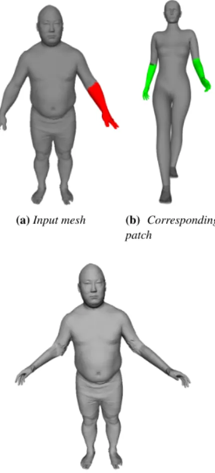
Another example is provided in Fig.7, which is more challeng-ing because the junction between the parts to transfer is located on the elbow. Moreover, both meshes have different resolutions and poses. The definition of corresponding rings of vertices, described in Section6.1, helps finding the correct alignment inside the el-bow. We can see that, while the alignment is performed efficiently, the target mesh regions are correctly transfered. Nevertheless, the difference in quality between the two meshes (resolution, triangle size, etc.) produces some artifacts.
(a) Input mesh (b) Corresponding patch
(c) Result mesh front view
Figure 7: Geometry transfer example. a) semantic selection on a given mesh, b) corresponding patch on another mesh, c) resulting mesh after stitching.
Table1gives average times (in milliseconds) of the main steps of the proposed method, on a standard desktop computer without GPU optimization. Note that the ellipsoid selection, the correspondence and the semantic alignment are achieved in near real time. These three computation times only depend on the number of triangles
c
in the mesh, whereas the stitching time depends on the SnapPaste parameters and stopping conditions.
Ellipsoid Corresp. Alignment Stitching Time 152.4 347.7 17.9 6.36 × 10³
Table 1: Execution times in milliseconds
8. Perspectives and conclusion
We have extended example-based modeling approaches to allow for the replacement of more arbitrary mesh regions that extend over multiple segments, or that are contained within a unique seg-ment. We believe this is an important step towards efficient artistic tools usable by hobbyists, as it allows for greater expressiveness. To achieve that, we have introduced a semantically based selection tool that makes use of a continuous semantic descriptor and ellip-soids. This tool retrieves all semantically similar mesh patches, and has potential for wider applications, from object retrieval to non-local mesh filtering operations. We have demonstrated that seman-tic information can be further used to improve the alignment and stitching of meshes, by adapting a (soft-)ICP procedure to handle semantics. Our approach runs in real time, and our results show that it is effective in creating new meshes by combining existing mesh pieces from a database.
Acknowledgement
This work has been partially supported by the ANR (Agence Nationale de la Recherche, France) through the CrABEx project (ANR-13-CORD-0013), and also partially supported by the region "Hauts de France" and the European Union with the European Re-gional Development Fund, in the frame of the MATRICE Project.
References
[AKZM14] AVERKIOU M., KIM V. G., ZHENG Y., MITRA N. J.: ShapeSynth: Parameterizing model collections for coupled shape explo-ration and synthesis. Computer Graphics Forum 33, 2 (May 2014), 125– 134.2
[BM92] BESLP.-J., MCKAYN.-D.: A method for registration of 3-D shapes. IEEE Transactions on Pattern Analysis and Machine Intelligence 14, 2 (1992), 239–256.5
[CK10] CHAUDHURIS., KOLTUNV.: Data-driven suggestions for cre-ativity support in 3d modeling. ACM Trans. Graph. 29, 6 (Dec. 2010), 183:1–183:10.2
[CKGF13] CHAUDHURI S., KALOGERAKIS E., GIGUERE S., FUNKHOUSERT.: Attribit: Content creation with semantic attributes. In ACM Symposium on User Interface Software and Technology (2013), pp. 193–202.1
[CKGK11] CHAUDHURIS., KALOGERAKISE., GUIBASL., KOLTUN
V.: Probabilistic reasoning for assembly-based 3d modeling. ACM Transactions on Graphics 30, 4 (July 2011), 35:1–35:10.1,2
[FKS∗04] FUNKHOUSER T., KAZHDAN M., SHILANE P., MIN P., KIEFERW., TALA., RUSINKIEWICZS., DOBKIND.: Modeling by Example. ACM Siggraph (2004).2
[FWX∗13] FANL., WANGR., XUL., DENGJ., LIUL.: Modeling by
drawing with shadow guidance. Computer Graphics Forum 32, 7 (2013), 157–166.1
[HKG11] HUANGQ., KOLTUNV., GUIBASL.: Joint shape segmen-tation with linear programming. ACM Transactions on Graphics 30, 6 (2011).2
[KCK12] KALOGERAKISE., CHAUDHURIS., KOLLERD.: A Proba-bilistic Model for Component-Based Shape Synthesis. ACM Transac-tions on Graphics(2012).2
[KH10] KALOGERAKISE., HERTZMANNA.: Learning 3D mesh seg-mentation and labeling. ACM Transactions on Graphics 29, 4 (2010).
2
[KJS07] KREAVOYV., JULIUSD., SHEFFERA.: Model composition from interchangeable components. Computer Graphics and Applications (2007), 129 – 138.1,2,3
[KLM∗12] KIM V. G., LI W., MITRA N. J., DIVERDI S., FUNKHOUSERT.: Exploring collections of 3d models using fuzzy cor-respondences. ACM Trans. Graph. 31, 4 (July 2012), 54:1–54:11.2
[KLM∗13] KIMV. G., LIW., MITRAN. J., CHAUDHURIS., DIVERDI
S., FUNKHOUSERT.: Learning part-based templates from large collec-tions of 3D shapes. ACM Transaccollec-tions on Graphics 32, 4 (July 2013).
2
[LBLV16] LÉONV., BONNEELN., LAVOUÉG., VANDEBORREJ.-P.: Continuous semantic description of 3d meshes. Computer & Graphics 54, C (Feb. 2016), 47–56.1,2,3
[Pow94] POWELLM. J. D.: Advances in Optimization and Numerical Analysis. Springer Netherlands, Dordrecht, 1994, ch. A Direct Search Optimization Method That Models the Objective and Constraint Func-tions by Linear Interpolation, pp. 51–67.4
[SBSCO06] SHARFA., BLUMENKRANTSM., SHAMIRA., COHEN-OR
D.: Snappaste: an interactive technique for easy mesh composition. The Visual Computer 22, 9-11 (2006), 835–844.2,5
[Smi15] SMITHMICRO: Poser Pro 11. http://my.smithmicro. com/poser-3d-animation-software.html, 2015. Online; accessed Feb. 2017.1
[SS10] SCHMIDTR., SINGHK.: Meshmixer: an interface for rapid mesh composition. In SIGGRAPH Talks (2010).2
[SSK∗05] SURAZHSKYV., SURAZHSKYT., KIRSANOVD., GORTLER
S. J., HOPPEH.: Fast exact and approximate geodesics on meshes. ACM Transactions on Graphics 24, 3 (July 2005), 553–560.3
[SvKK∗11] SIDI O., VAN KAICK O., KLEIMAN Y., ZHANG H., COHEN-ORD.: Unsupervised co-segmentation of a set of shapes via descriptor-space spectral clustering. ACM Transactions on Graphics 30, 6 (2011).2
[TSS∗11] TAKAYAMA K., SCHMIDT R., SINGH K., IGARASHI T.,
BOUBEKEURT., SORKINEO.: GeoBrush: Interactive Mesh Geome-try Cloning. In Computer Graphics Forum (2011), vol. 30, pp. 613–622.
2
[vKTS∗11] VANKAICKO., TAGLIASACCHIA., SIDIO., ZHANGH., COHEN-ORD., WOLFL., HAMARNEHG.: Prior Knowledge for Part Correspondence. Computer Graphics Forum 30, 2 (2011).2
[vKXZ∗13] VANKAICKO., XUK., ZHANG H., WANGY., SUNS., SHAMIRA.: Co-Hierarchical Analysis of Shape Structures. ACM Trans-actions on Graphics 32, 4 (2013).2
[XXM∗13] XIEX., XUK., MITRAN. J., COHEN-ORD., GONGW., SUQ., CHENB.: Sketch-to-design: Context-based part assembly. Com-puter Graphics Forum 32, 8 (2013), 233–245.1,3
![Figure 1: Illustration of the semantic descriptor of Léon et al. [LBLV16]. Here, a three-dimensional descriptor is considered, and each dimension represents the distance to points labeled as (a) Head, (b) Foot and (c) Hand respectively](https://thumb-eu.123doks.com/thumbv2/123doknet/12500200.340212/3.892.475.809.137.356/illustration-descriptor-dimensional-descriptor-considered-dimension-represents-respectively.webp)